International Journal of Scientific & Engineering Research, Volume 6, Issue 3, March-2015
ISSN 2229-5518
Wireless Sensor Network for Machine Health
Monitoring
Pooja Rai, Sourav Dhar, Depanjan Bhattacharjee
Abstract— Wireless Sensor Network has a growing demand worldwide. This network plays a vital role in creating reliable and scalable system making human life easier and faster. WSN is a sensitive network which is effective and efficient. In this paper we have implemented WSN for keeping regular updates on a health of a machine and its control. For wireless communication purpose Zigbee protocol is deployed. Required algorithms have been developed allowing evaluation of additional parameters using data from measurements held.
Index Terms—. Wireless Sensor Network(WSN),Current Transformer(CT)
728
1 INTRODUCTION
—————————— ——————————
Wireless sensor network popularity is increasing because of its unlimited potential. Most common application of WSN is to monitor remote environments for low frequency data transfer. Other applications are telemedicine, industrial automation, earth sensing [1]. WSN is a vast network in physical scenario. This network brings several advantages over old wired net- work. WSN’s primary requirements are sensor node, router and a coordinator. This network has to be cost effective be- cause deployment of hundreds of sensor nodes will be costly. Next best thing of WSN i.e. need of infrastructure is not man- datory even a lamp post can be used. When it comes to im- plementing WSN several factors comes into the light like low cost and small sensor nodes are preferred, low cost and low power consuming hardware are needed. For wireless commu- nication purpose there are many standardized protocols [2]. Among all the standardized wireless communication protocol, Zigbee is widely used in measurement equipment’s because of its capabilities to provide easy maintenance, low energy con- sumption, diverse network topologies, easy installation etc. Zigbee standard is very much suitable for remote wireless system placed for monitoring various surrounding parame- ters. Zigbee protocol uses are in all fields from top class indus- trial automation to simple home appliances. Zigbee standard provides high reliability and immunity against interferences [3].
This paper fully intend to design a hardware wireless system with well-coordinated wireless sensor network for monitoring
————————————————
Ms. Pooja Rai is currently pursuing master degree in electronics and Communication engineering in Sikkim Manipal Institute of Technology, India, E-mail: aquarai@ymail.com
Dr. Saurav Dhar is a Associate Professor of electronics and communication engineering in Sikkim Manipal Institute of Technology, India.
Mr. Depanjan Bhattacharjee is a Assistant Professor of electronics and communication engineering in Sikkim Manipal Institute of Technology, India.
and control of AC Motor suitable for industrial automation.
The designed wireless modules can be installed at almost any place because of their compact size. The best part of this im- plementation process i.e., the WSN created can be enlarged by constructing more sensing nodes and adding them to the par- ent network.
2 DETAIL OF HARDWARE AND SOFTWARE
Hardware and software both are important for smooth func- tioning of a sensor network. Detail of hardware and software as given below:
2.1 Hardware
Arduino board: Arduino board is a microcontroller board based on ATmega328.It has 14 digital input / output pins and 6 analog pins. It comes with a 16
MHz crystal oscillator, a USB cable, a power jack and
a reset button .This board has everything needed to
support a microcontroller. Its operating voltage is
5volts and input voltage recommend is 7volts to 12
volts. It has 32 KB flash memory which is repro- grammable.2KB of SRAM and 1KB of EEPROM is al- so present.
Xbee RF module: It is embedded RF module which provides cost-effective wireless connectivity. It is compact radio module which works in Zigbee proto- col. This module is immune to interference so it helps to build a more coordinated network. It is interoper- able with other Zigbee standard devices. Its works in
2.4 GHz frequency band which comes under ISM frequency band. It operates at 5 volts. Xbee RF mod- ule can be configured into a coordinator, a router or end devices. It is facilitated with firmware which helps to modify Xbee module into any three configu- rations mentioned earlier.
IJSER © 2015 http://www.ijser.org
International Journal of Scientific & Engineering Research Volume 6, Issue 3, March-2015
ISSN 2229-5518
729
Sensor (as per requirement): Sensors are devices de- signed to be sensitive to some factors. This device de- tects events or changes in that certain factor and also provides corresponding output. Henceforth only needed sensors are discussed.
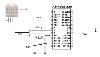
DHT 11 Temperature and Humidity Sensor feature a temperature & humidity sensor complex with a cali- brated digital signal output. The exclusive digital- signal-acquisition technique and temperature & hu- midity sensing technology are used in its design. It has high reliability and excellent long-term stability. This sensor includes a resistive type humidity mea- surement component & a NTC temperature mea- surement component. The single –wire serial inter- face makes system integration quick and easy. Its small size, low power consumption and up-to- 20 meter signal transmission making it the best choice for various application. DHT11‘s power supply is 3-
5.5 v DC. It can be connected to any type of micro-
controller.
Current transformer used in measurement of current and voltage is usually placed in the main circuit basi- cally to step down a high current circuit to drive a low current device. It is very useful in measuring or monitoring high current, high voltage and high pow- er circuit. Current transformers have various applica- tions in electrical circuits. There are two winding in a current transformer. One is primary winding with high current and another is secondary winding with low current. In current transformers regardless of what change may be made to secondary winding load, the primary winding current is always same as that of the main circuit. Precaution must be taken that CT should never be open circuited while main current is passing through the primary windings.
2.2 Software
Arduino Software: Arduino software is the lifeline of Arduino board. Since Arduino board is microcontrol- ler based and to run it, some algorithms are required. All these algorithms are written in Arduino software. This software is user friendly and can be downloaded for free from internet.
X-CTU software: X-CTU is a graphical windows- based serial utility. X-CTU software is used to pro- gram and configure firmware of Xbee module. X-CTU is designed to function with all windows-based com- puters. X-CTU focuses on modem configuration and changing profile on Xbee module. This software can either be downloaded from Digi’s web site or an in- stallation CD. This software provides consumers with options of selecting desired com port and configure that comport to fit the radio setting of hardware module .It also allows customer to perform range test between two modules.
WSN consists of one wireless module to collect data (as coor- dinator), one router device for routing and smooth flow of data and finally end devices (sensor node).All the designed module communicates wirelessly using Zigbee standard. Data collected are visualized in a display platform may be laptop or PC. The general structure of developed Wireless Sensor Net- work is presented in Fig 1.
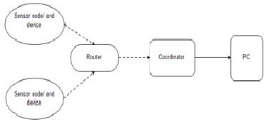
Fig1. General diagram of WSN
3 DESIGN OF PROPOSED WIRELESS SENSOR NETWORK
In this section of paper we discuss designing of wireless sen- sor network as well as design of sensing nodes. For designing sensing module a microcontroller, a sensor, power supply and a transreceiver is required thereafter all the wireless modules are connected to create a Wireless Sensor Network using Xbee and RF module.
3.1 Coordinator module
A coordinator device can be used as standalone measurement equipment with diverse communication capabilities. To facili- tate wireless network coordinating function, it may be equipped with Zigbee module, GSM/GPRS or Ethernet mod- em for expanding the system over the internet. The coordina- tor device can also be used as data logger. A coordinator de- vice is always active and always ready to receive data from all the surrounding nodes. Failure of coordinator will disrupt the whole network.
Design of coordinator basically consists of a microcontroller with low power consumption and some memory .For wireless communication one wireless module is necessary. Wireless module is powered up via microcontroller. Consumption of power has always been an important issue in WSN. The WSN created in this implementation process, Coordinator plays a strong role of gathering all the data. More detail of working of this module is discussed with each component, which is con- nected to construct coordinator.
Microcontroller: Its main task is to acquire data which
are sent from router. It not only receives data but also
reads it. It gives command to send and print data. Mi-
crocontrollers also perform control and configuration of all types of communication module. Microcontrol-
IJSER © 2015 http://www.ijser.org
International Journal of Scientific & Engineering Research Volume 6, Issue 3, March-2015
ISSN 2229-5518
730
ler of coordinator is supposed to receive data from router and not any end devices. And in some cases it sends back data to end device via router only.
Xbee RF Module: This module is used to facilitate wireless connection between other wireless modules of WSN. It is controlled standard AT commands over a serial communication interface. It has very low power consumption and is suitable for battery po- wered system. Xbee RF module is configured as coor- dinator. All the data are collected here because they all have destination address set as address of router. Whereas destination address of router is address of a coordinator so all the data sent by router is received by coordinator.
Real time clock and EEPROM: Real time clock (RTC)
implements the time synchronization .It also defines
the measurement interval between two adjacent data
sample. Whereas EEPROM is for storing data, since in
this wireless network data collected are immediately
sent to display so EEPROM is of 1KB.
Power supply: In order to implement its full functio-
nality, the coordinator device is powered up by 5
volts through power jack or USB. Batteries can be
used as well.
Router module
A router device is used for networking purpose. Router for- wards data packets between any two or more than two net- works. It is connected to two or more data lines from different networks. Whenever data reaches a router, router reads the address information in the packet and determines its imme- diate destination. It is not allowed to be in a sleep mode or off state as continues communication is always necessary between different networks. Router makes it easier to add a new sensor node into the parent or already existing network. Thus crea- tion of an overlay internetwork comes into being.
Design of router basically consists of a microcontroller with low power consumption and memory is not necessary. Xbee RF module for wireless communication is required and confi- gured as router. The WSN created in this implementation process, router plays a strong role of forwarding all the data to their destination. More detail of working of this module is discussed with each component, which is connected to con- struct router.
Microcontroller: Its main task is to acquire data which
are sent by all the end devices and forward that data to the coordinator. It only receives the data and for- wards it again. It gives command to send data to coordinator. Microcontrollers also perform control and configuration of communication module. Micro- controller of router is supposed to receive data from end devices only and in some exceptional cases it receives from coordinator but that is rare. Microcon- troller also power ups the wireless module.
Xbee RF Module: Xbee module is configured as rou- ter. Router collects all the data from more than one end device and sends these data to coordinator. This happens because the destination address of router is address of coordinator whereas destination address of all the end devices is address of router.
Real time clock and EEPROM: Real time clock (RTC) implements the time synchronization .It also defines the measurement interval between two adjacent data sample. Whereas EEPROM is for storing data, since in router storing of data are not necessary so there is no requirement of EEPROM.
Power supply: In order to implement its full functio- nality, the coordinator device is powered up by 5 volts through power jack or USB. Batteries can be used as well.
End devices (sensor nodes)
Wireless Sensor Network is a collection many sensor nodes and some routers and coordinators. Sensor nodes or End de- vices are responsible for the size of network and even the ex- tension of the network. More the sensor nodes larger will be the network. They play a vital role in the network as they are the sensitive devices exposed to the area which are chosen for monitoring. They are allowed to be in a sleep mode whenever not required. Sleep mode of end devices helps in saving pow- er. In this implementation process two end devices are de- signed with different kind of sensing parameter.
Design of end device basically consists of a microcontroller with low power consumption and some memory. Xbee RF module for wireless communication is required and confi- gured as end device. In the wireless sensor network created in this implementation process, end devices are responsible for sensing part of network. Special sensors are deployed to sense different parameter. End device work is to sense that special parameter and keep the changing track of that parameter in the form of data. Simultaneously data are sent to the router to reach their destination. More detail of working of this module is discussed with each component, which is connected to con- struct end device
Microcontroller: Its main task is to keep update of
sensed data coming from sensor and send the sensed data. In this implementation process DHT11(Temperature and Humidity sensor) and CT(Current transformer) is used in order to sense ma- chine’s temperature and humidity of air around it and to see how much voltage and current is present at a particular time respectively. It gives command to send data to router. Microcontrollers also perform control and configuration of communication module. Microcontroller of end device is supposed to send da- ta to router only and router forwards it to coordina-
IJSER © 2015 http://www.ijser.org
International Journal of Scientific & Engineering Research Volume 6, Issue 3, March-2015
ISSN 2229-5518
731
tor. Microcontroller also power ups the wireless module.
Xbee RF Module: This module is configured as end device. End device are connected to coordinator only through router. End device destination address is the address of the router. So all the data send first reaches router. Next, destination address of router is the ad- dress of coordinator. Finally data reaches destination for analysis.
Real time clock and EEPROM: Real time clock (RTC) implements the time synchronization .It also defines the measurement interval between two adjacent data sample. EEPROM is for storing data.
Power supply: In order to implement its full functio-
nality, the end device is powered up by 5 volts through power jack or USB .Batteries can be used as well.
Fig.1 DHT11 sensor connected to ATmega328
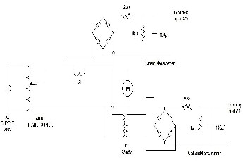
Fig.2 Circuit diagram for current and voltage Measurement using current transformer.
4 PERFORMANCE ANALYSIS AND RESULTS OBTAINED
Since the WSN is well designed and developed, to test the ability of the same some parameters of AC motor is measured. Measured parameters of AC motor are temperature, humidity,
current, voltage. The setup of this design is such that, the end device or the sensor node is placed in the same room where motor is running whereas coordinator is placed in the adjacent room. Router is placed with equal distance from sensor node as well as coordinator. The wireless communication is possible between them because the Xbee RF module’s range is 40 me- ters indoor and 120 meters outdoor. Motor is provided with supply. Sensor node is already powered up. On the other side coordinator is flooded with data. From coordinator, all the values for all the parameter are picked and stored for further analysis.
After data acquisition process is completed. Analysis is done over the acquired data. It is seen from the acquired and graph plotted from the same that the temperature of the motor is increasing and humidity is decreasing with respect to time. This data is collected from the sensor node where DHT11 sen- sor is connected (ref Fig.1 Section III). Initially temperature and humidity is constant after motor is powered up tempera- ture has increased gradually and humidity is decreased. While collecting the required data no interruption was caused in communication between wireless modules and no data loss took place. The graph of the same is given below.
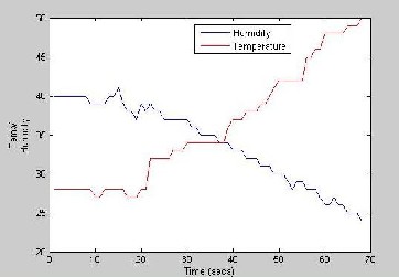
Fig.1 Variation of Humidity and Temperature
Next for the current and temperature measurement, a circuit is designed (ref Fig.2 Section III) .This circuit is designed and con- nected with the motor as shown in the figure. Motor is powered up and the readings are taken via analog input of the AT mega 328. Collected data are analyzed further and graph is plotted for the same. Firstly all the data are acquired from the sensor node with- out interruption and no data loss is there. After the data acquisi- tion, data analysis resulted in a graph shown below.
IJSER © 2015 http://www.ijser.org
International Journal of Scientific & Engineering Research Volume 6, Issue 3, March-2015
ISSN 2229-5518
732
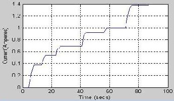
Fig .2 Current Vs. time
In the above graph, it is seen that current is increasing with the passing time. Autotransformer as the source to the motor, the source is fluctuating. According to the source the response of the current graph is shown above. It is seen from the graph that at some level the current value is constant ,it is so because the autotransformer voltage is kept constant for a while to get the check whether data that are received are correct or not. After that source voltage is increased gradually so the current value.
Next voltage across the motor is measured. The same circuit is
used (ref Fig.2 Section III). Motor is powered up and data are
collected via another analog input. The same process is fol-
lowed as for above. The voltage response graph is given be-
low.
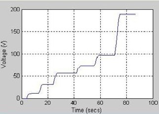
Fig.3 Voltage vs. Time
The source for the circuit is autotransformer like that of cur- rent. So the voltage across the motor is increasing as passing time. At some points the voltage value is constant as the source was kept constant for the same reason to check whether the show data are corresponding response to source or not. Finally after analyzing all the data, it is seen that response of the sensor node was noticeable and so was the whole WSN. Data are corrected and giving right response as per motor’s activities. Thus the four parameter of motor will be kept under constant supervision for its up to date health.
5 CONCLUSION
Wireless Sensor Network for remote monitoring of AC single phase motor has been designed and described. The detailed experimental study confirms the good performance of WSN as well as all the other hardware used. Such type of research and results obtained can be used for analyzing and designing other types of remote monitoring system for various purposes. Im- plementation of WSN was half easier due to Xbee RF module. The configuration of modules was using X-CTU software. All the sensors and circuit components are of reasonable cost as needed for implementation of WSN.
The evaluations of this implementation process were done. All the needed algorithms were developed and analysis of all the acquired data has been done and presented. While designing this WSN, it has to be kept in mind that cost of the research, since WSN are very costly and there are various standards of wireless communication. Choosing the suitable hardware will reduced configuration and cost problem.
Thus, this experimental study confirms that checking the health of motor (or any other machine) is not tiresome and simply by creating WSN, the health of the machine can be su- pervised. Next, there is other more potential research related to WSN. This implementation process gives a light on the in- dustrial automation field.
REFERENCES
[1] Miguel Angel Reyes, Grant W. King, Gregory G. Miller,” Intelligent Machine
Guard Monitoring “IEEE industry application magazine march/april2014.
[2]V.C Gungor and C.P. Hancke, “Industrial Wireless Sensor Networks : Chal- lenges, Design Principle, and Technical Approaches, “IEEE Trans.Ind.Electron, vol.56, no.10,pp.4258-4265, Oct.2009
[3] L.Q.Zhuang, K.M.Goh and J.B.Zhang, “The Wireless Sensor Network for Facto- ry Automation: Issues and Challenges” 1-4244-0826-1/07/2007 IEEE
[4] I.F.Akyildiz, W.Su, Y.Sankarasubramaniam and E. Cayirci, “Wireless Sensor
Networks: a Survey”, Computer Networks, Vol.38.pp.393-442, 2002
[5] T. Ciardiello, “Wireless Communication for Industrial Control and Monitoring
“, Journal of computing & Control Engineering, Vol.16, No.2, pp.12-13, 2005
[6 ]X.Shen, Z. Wang and Y.Sun, “Wireless sensor networks for industrial applica- tions,” in Proc. 5th World Congr. Control Autom, 2004, pp. 3636-3640.
[7] I.F. Akyildiz, T.Melodia, and K. Chowdhury, “A survey on wireless multimedia sensor networks,” Comput.Netw, vol.51, no. 4, pp. 921-960, Mar.2007
[8] D.Dzung, C.Apneseth, J.Endersen, and J.E Frey, “Design and Implementation of a real-time wireless sensor / actuator communication system,” in Proc.IEEE Conf., Emerg.Technol. Factory Autom, 2005, p.442
[9 ]H. Zhi-gang and C. Cai-hui, “The Application of ZigBee Based Wireless Sensor Network and GIS in the Air Pollution Monitoring,” in Proceedings of ICE- SIAT’09, pp. 546-549, Wuhan, China, 2009
IJSER © 2015 http://www.ijser.org
International Journal of Scientific & Engineering Research Volume 6, Issue 3, March-2015
ISSN 2229-5518
733
[10] B. Zaineb, B. Mouna and L. Sbita, “Wireless Control for an Induction Motor,” International Journal of Electrical and Electronics Engineering, vol. 5, no. 1, pp.
1-5, 2011.
[11] C. Hernandez, R. Poot, L. Narvaez, E. Llanes and V. Chi, “Design and Imple- mentation of a System for Wireless Control Of a Robot,” International Journal of Computer Science, vol.7, no.5, pp.191-197, 2010.
[12]Niteen Deshmukh and Pravin N.Matte, “An Application of Zigbee for Machine Health Monitoring” International Journal of Innovative Research in Science, Engineering and Technology, Vol.3, Issue 3, March 2014.
[13]Mikho Mikhov, Nikolay Stoyanov, Georgi Stanchev and Zdravko Doichev, “An Application of wireless standards for Remote Monitoring of Electric Drive System”, International Journal of Engineering Research & Develop- ment , vol.2, Issue 12, pp.30-36
[14] S. Dhar, A. Ray and R.Bera (2012), “Cognitive Vertical Handover Engine for Vehicular Communication”, Peer to Peer Netw. And Appl., Springer, New York. 2012.; doi: 10.1007/s12083-012-0171-5
IJSER © 2015 http://www.ijser.org