International Journal of Scientific & Engineering Research, Volume 3, Issue 2, February-2012 1
ISSN 2229-5518
Wireless Monitoring of the Green House System
Using Embedded Controllers
Miss.Vrushali R. Deore , Prof. V.M. Umale.
Abstract--Plant growth is affected by various factors. The most important factors for the quality and productivity of plant growth are temperature, humidity, light. Continuous monitoring of these environmental variables gives information to the grower to better understand, how each factor affects growth and how to manage maximal crop productiveness. The optimal greenhouse climate adjustment can enable us to improve productivity and to achieve remarkable energy savings - especially during the winter in northern countries. The main purpose of a greenhouse is to provide and maintain the environment that will result in optimum crop production or maximum profit. This includes an environment for work efficiency as well as for crop growth. There has been much research and design about environment control using sophisticated technology. [23] In the present paper, authors have given an emphasis on WSN approach for green house monitoring and control. A control system is developed and tested using recent Atmega microcontroller. The farmers in the developing countries can easily use designed for maximizing yield. Atmega microcontrollers are preferred over other microcontrollers due to some important features including 10- bit ADC, sleep mode , wide input voltage range and higher memory capacity.
KEYWORDS: WSN, AVR, RF2.4, MICROCONTROLLERS, GREEN HOUSE, PRECISION AGRICULTURE.
—————————— ——————————
1.INTRODUCTION
A recent survey of the advances in wireless sensor network applications has reviewed a wide range of applications for these networks and identified agriculture as a potential area of deployment together with a review of the factors influencing the design of sensor networks for this application. WSN is a collection of sensor and actuators nodes linked by a wireless medium to perform distributed sensing and acting tasks. The sensor nodes collect data and communicate over a network environment to a computer system, which is called, a base station. Based on the information collected, the base station takes decisions and then the actuator nodes perform appropriate actions upon the environment. This process allows users to sense and control the environment from anywhere. There are many situations in which the application of the WSN is preferred, for instance, environment monitoring, product quality monitoring, and others where supervision of big areas is necessary.
Wireless sensor network (WSN) form a useful part of the automation system architecture in modern greenhouses. Wireless communication can be used to collect the measurements and to communicate between the centralized control and the actuators located to the different parts of the greenhouse. In advanced WSN solutions, some parts of the control system itself can also be implemented in a distributed manner to the network such that local control loops can be formed. Compared to the cabled systems, the installation of WSN is fast, cheap and easy. The only additional costs occur when the sensor nodes run out of batteries and the batteries need to be charged or replaced, but the lifespan of the battery can be several years if an efficient power saving algorithm is applied. [9]
The research on the use of WSN in agriculture is mainly
focused primarily on areas such as Proof-of-concept applications to demonstrate the efficiency and efficiency of using sensor networks to monitor and control agriculture management strategies. The attempt is made by the authors to show the effective utilization of this concept into day to day monitoring of the green house for higher yield. [1]
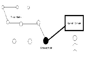
Fig.1. Wireless Sensor Network
2. SYSTEM REQUIREMENTS
2.1 Low-cost, low-power, small size networking devices
The system to be used should be cost effective, small in size and should require less mobility during its functioning. If the system is wireless then it should work on any unlicensed band. It also should require lesser hardware.
IJSER © 2012 http://www.ijser.org
International Journal of Scientific & Engineering Research, Volume 3, Issue 2, February-2012 2
ISSN 2229-5518
2.2 Long battery life
Long battery life is needed for the use in developing countries due to frequent power shortage
2.3 Robust design
Developed prototype of WSN should withstand with variations in the temperature, humidity, rain and wind speed.
2.4 User friendliness
Developed prototype of WSN should have GUI and must be easy to understand and work upon In nutshell, socio- economic status of the farmers needs also to be considered while finalizing the prototype of WSN. [15]
3. EXPERIMENTAL SET-UP
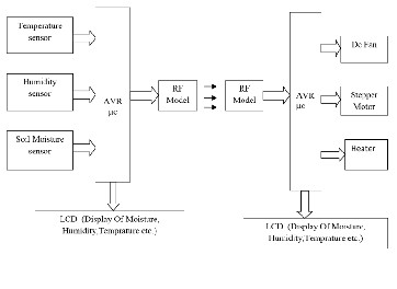
In the proposed hardware, there would be two section master and slave. The slave part would contain the temperature and humidity sensor, soil moisture sensor. The sensor would be connected to the AVR microcontroller. The RF transceiver would be connected to the AVR microcontroller which would wirelessly send the data to the master part. The master part would contain the RF transceiver which would receive the data and give to the microcontroller. The count would be displayed on the graphics LCD. The motor and DC fan would also be connected to the master board. These motor and DC fan would be accordingly controller based upon the relevant temperature and humidity condition. The major components of the proposed hardware, as seen in fig.2, are,
4. USEFUL FEATURES OF AVR
MICROCONTROLLERS
The ATmega16 provides the following features: 16K bytes of In-System Programmable flash Program memory with Read-While-Write capabilities, 512 bytes EEPROM, 1K byte SRAM, 32 general purpose I/O lines, 32 general purpose working registers, a JTAG interface for Boundary scan, On- chip Debugging support and programming, three flexible Timer/Counters with compare modes, Internal and External Interrupts, a serial programmable USART, a byte oriented Two-wire Serial Interface, an 8-channel, 10-bit ADC with optional differential input stage with programmable gain (TQFP package only), a programmable Watchdog Timer with Internal Oscillator, an SPI serial port, and six software selectable power saving modes. The Idle mode stops the CPU while allowing the USART, Two-wire interface, A/D Converter, SRAM; Timer/Counters, SPI port, and interrupt system to continue functioning. The Power-down mode saves the register contents but freezes the Oscillator, disabling all other chip functions until the next External Interrupt or Hardware Reset. In Power-save mode, the Asynchronous Timer continues to run, allowing the user to maintain a timer base while the rest of the device is sleeping.
The ADC Noise Reduction mode stops the CPU and all I/O modules except Asynchronous Timer and ADC, to minimize switching noise during ADC conversions. In Standby mode, the crystal/resonator Oscillator is running while the rest of the device is sleeping. This allows very fast start-up combined with low-power consumption. In Extended Standby mode, both the main Oscillator and the Asynchronous Timer continue to run. The device is manufactured using Atmel’s high density nonvolatile memory technology. The On chip ISP Flash allows the program memory to be reprogrammed in-system through an SPI serial interface, by a conventional nonvolatile memory programmer, or by an On-chip Boot program running on the AVR core. The boot program can use any interface to download the application program in the Application Flash memory. Software in the Boot Flash section will continue to run while the Application Flash section is updated, providing true Read-While-Write operation. By combining an 8-bit RISC CPU with In-System Self-Programmable Flash on a monolithic chip, the Atmel ATmega16 is a powerful microcontroller that provides a highly-flexible and cost- effective solution to many embedded control applications.
Fig.2 Block Diagram of system.
The ATmega16 AVR is supported with a full suite of
program and system development tools including: C compilers, macro assemblers, program debugger/simulators, in-circuit emulators and evaluation kits. [11]
IJSER © 2012 http://www.ijser.org
International Journal of Scientific & Engineering Research, Volume 3, Issue 2, February-2012 3
ISSN 2229-5518
5. RF COMMUNICATION
RF is the wireless transmission of data by digital
radio signals at a particular frequency. RF communication works by creating electromagnetic waves at a source and being able to send the electromagnetic waves at a particular destination. These electromagnetic waves travel through the air at near the speed of light. The advantages of a RF communication are its wireless feature so that the user needn’t have to lay cable all over the green house. Cable is expensive, less flexible than RF coverage and is prone to damage. RF communication provides extensive hardware support for packet handling, data buffering, burst transmissions, clear channel assessment and link quality.
5.1 WHY RF 2.4?
The important features given below make RF 2.4 an ideal choice for green house parameter Monitoring
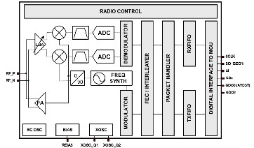
The CC2500 is a low-cost 2.4 GHz transceiver designed for very low-power wireless applications. The circuit is intended for the 2400-2483.5 MHz ISM (Industrial, Scientific and Medical) and SRD (Short Range Device) frequency band.[20]
The RF transceiver is integrated with a highly configurable baseband modem. The modem supports various modulation formats and has a configurable data rate up to 500 kBaud
CC2500 provides extensive hardware support for
packet handling, data buffering, burst transmissions, clear channel assessment, link quality indication and wake-on-radio.[14]
The main operating parameters and the 64-byte transmit/receive FIFOs of CC2500 can be controlled via an SPI interface. In a typical system, the CC2500 will be used together with a microcontroller and a few additional passive components.
In nutshell, the advantages of RF 2.4 are,
Low power consumption.
Integrated data filters.
High sensitivity
Operation temperature range -40~+85 deg C
Available frequency at : 2.4~2.483 GHz- No certification
Required from government
High accuracy
Low cost
6. SENSORS
I. TEMPERATURE SENSOR
In this project for the measurement of Temp, temp sensor should have the following parameters,
• Linearity: Temperature sensor should have linear temperature to voltage characteristics.
• Sensitivity : Should be able to produce voltage for
small change in temperature input
• Minimum Drift: Should give similar reading for
same input over the years.
Basically, IC temperature sensors are nothing but silicon PN junctions. Surrounding Temperature increases reverse saturation current producing voltage (output voltage) across the fixed load resistor. The output voltage is directly proportional to absolute temperature. The various IC temp sensors available are, [17]
• LM135, LM235, and LM335 – it provides an output of 10mV/K
• LM35 –it provides an output of 10mV/ºC
• LM34 –it provides an output of 10mV/ºF
Fig.3 Functional Diagram
National semiconductor’s LM35 IC has been used for
sensing temperature, whose output voltage is linearly
proportional to the Celsius (Centigrade) temperature. The LM35 thus has an advantage over linear temperature sensors calibrated in ° Kelvin, as the user is not required to subtract a large constant voltage from its output to obtain convenient Centigrade scaling. The LM35 does not require any external calibration or trimming to provide typical accuracies of
IJSER © 2012 http://www.ijser.org
International Journal of Scientific & Engineering Research, Volume 3, Issue 2, February-2012 4
ISSN 2229-5518
±1.4°C at room temperature and ±3.4°C over a full -55 to
+150°C temperature range. Low cost is assured by trimming and calibration at the wafer level. The LM35’s low output impedance, linear output, and precise inherent calibration make interfacing to readout or control circuitry especially easy. It can be used with single power supplies, or with plus and minus supplies. As it draws only 60 µA from its supply, it has very low self-heating, less than 0.1°C in still air. The LM35 is rated to operate over a -55° to +150°C temperature range, while the LM35C is rated for a -40° to +110°C range (-
10° with improved accuracy). The LM35 series is available packaged in hermetic TO-46 transistor packages, while the LM35C, LM35CA, and LM35D are also available in the plastic TO-92 transistor package.
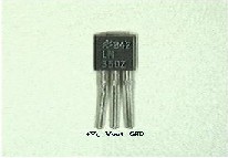
Fig 4. Temp Sensor
II. HUMIDITY SENSOR
Absolute Humidity is the exact measure of the amount of water vapor in the air. It is normally expressed in terms of relative humidity. Relative humidity, expressed as a percent, is the ratio of actual moisture in the air to the highest amount of moisture air at that temperature can hold. A capacitive device with special material as a dielectric, the electrical characteristics of which change according to the amount of humidity in the air. [1]
The sensor circuit develops a linear voltage output vs. %RH Chemically resistant (output is not disturbed due to the presence of chemicals in the air).The HIH-3610 Series humidity sensor is designed specifically for high volume OEM (Original Equipment Manufacturer) users. Direct input to a controller due to sensor’s linear voltage output. With a typical current drawn is only 200 mA, the HIH-3610 Series is ideally suited for low drain, battery operated systems. The HIH-3610 Series delivers instrumentation-quality RH (Relative Humidity) sensing performance in a low cost, solder able SIP (Single In-line Package). Available in two lead spacing configurations, the RH sensor is a laser trimmed thermo set polymer capacitive sensing element with on-chip integrated signal conditioning. The sensing element's
multilayer construction provides excellent resistance to
application hazards such as wetting, dust, dirt, oils, and common environmental chemicals.
III. SOIL MOISTURE SENSOR:
Functional description of Soil moisture sensor:
The copper plate act as the sensor probes. They are immersed into the specimen soil whose moisture content is under test. The soil is examined under three conditions:[17]
L o w ( Dry) condition- The probes are placed in the soil under dry conditions and are inserted up to a fair depth of the soil. As there is no conduction path between the two copper leads the sensor circuit remains open. The output in this case ranges from 0 to 30%.
Case#2: Medium (Optimum) condition- When water is added to the soil, it percolates through the successive layers of it and spreads across the layers of soil due to capillary force. This water increases the moisture content of the soil. This leads to an increase in its conductivity which forms a conductive path between the two sensor probes leading to a close path for the current flowing from the supply to the sensor probes. The output of the circuit in the case ranges from 31% to 60% approximately.
Case#3: High(Excess water ) condition - With the increase in water content beyond the optimum level, the conductivity of the soil increases drastically and a steady conduction path is established between the two sensor leads and the voltage output from the sensor increases no further beyond a certain limit. The maximum possible value for it is selected between 61%to 100%. [21]
7. DESIGN OBJECTIVES
The horticulturists near Nasik region felt the need of some automatic controller for their green houses where they grow export quality roses. The atmosphere in India change with great variance with the season. Hence, the quality of the roses does not remain the same due to the great change in the temperature and humidity parameters. Roses with adverse quality give less income. The loss in the income due to adverse quality roses is to the tune of 2 to 3 lakhs per acre per season. For roses, ideally, the green house should provide good light throughout the year, temperature range between 15 to 28°C, night temperature should be between 15 to 18°C, and the day temperature should not exceed 30°C in any case. The growth is slowed down with the fall of temperature below 15°C. If the temperature rises above 28°C, humidity must be kept high. Higher night temperature
IJSER © 2012 http://www.ijser.org
International Journal of Scientific & Engineering Research, Volume 3, Issue 2, February-2012 5
ISSN 2229-5518
above 15°C hastens flower development, while lower temperature around 13.5°C delays it.
Depending on the temperature inside the greenhouse, the moisture should be kept in line for the best results. For example, if the temperature is 24 degrees, 60% humidity is suitable.
Hence, variable temperature and humidity control for different crops using wireless technique for WSN environment using low cost technique was the main objective. Low power consumption during testing was another objective. Hence, selection of the sensors and most importantly, microcontroller, was very important keeping power consumption at remote places in view. To bring the temperature within control limit, exhaust fans were made automatically ON and for humidity control, water pump was made ON-OFF.
8. FIELD OBSERVATIONS
Readings were taken for 03 months (March, May, and August). ON-OFF action of the hardware was tested. Satisfactory results were achieved. Fig. shows the photographs of the green house structures used to take readings.

Fig. 5: Green house near Nasik growing roses was used for testing of suitable control action for green house parameters with the help of AVR based green house controller.
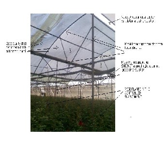
Fig. 6: Green house near Nasik growing roses: Complete sections of the green are seen. Vents are used to regulate the temperature, naturally.
9. RESULTS
Results are found to be satisfactory. Area A and B (each admeasuring 10 meters x 10 meters) were selected. Area A is used to take reading without temperature and humidity control. Readings in Area B were taken after suitable automatic control action with the help of AVR based green house controller. It is found that the designed hardware has shown consistently faithful readings and also proved to be accurate in the humid atmosphere of the green house. Following readings and graphs show some of the readings in Area A and corresponding readings after corrective action in Area B.
DATE:-30/3/11

Fig. 7: Green house parameters in AREA A (without control action)
IJSER © 2012 http://www.ijser.org
International Journal of Scientific & Engineering Research, Volume 3, Issue 2, February-2012 6
ISSN 2229-5518
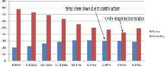
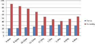
Fig. 7: Green house parameters in AREA B (with control action). Humidity values are increased and temperature values are decreased due to automatic control action of AVR based wireless green house controller.
DATE:- 10/05/11
DATE:- 28/08/11
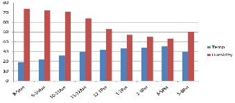
Fig. 8: Green house parameters in AREA A (without control action)
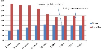
Fig. 8: Green house parameters in AREA B (with control action). Humidity values are increased and temperature values are decreased due to automatic control action of AVR based wireless green house controller.
Fig. 9: Green house parameters in AREA A (without control action
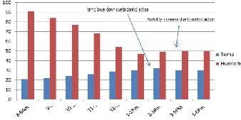
Fig. 9: Green house parameters in AREA B (with control action). Humidity values are increased and temperature values are decreased due to automatic control action of AVR based wireless green house controller.
IJSER © 2012 http://www.ijser.org
International Journal of Scientific & Engineering Research, Volume 3, Issue 2, February-2012 7
ISSN 2229-5518
VI. The system developed has shown consistency,
accuracy and precise control action over a period of
15 days and did not fail even once during testing.
VII. Green house control system found effective even in humid atmosphere.
VIII. Quality of roses in area B found to good than area A. IX. Owner of the green house said that the good quality
roses are sold at 1.5 time’s higher rate than medium
quality roses. Hence, the system, if implemented,
can increase the profit margin.
X. The cost of the system is less than Rs. 2500/- if produced in multiple.
XI. For one acre green house, we need only 5 sets of
AVR based green house controllers.
XII. Projected increase in the profit is in the range of 4-5 lakhs per acre.
11. REFERENCES
[1]BeomJin Kang Dae, Heon Park, KyungRyung Cho, ChangSun Shin, SungEonCho , JangWoo Park “A Study on the Greenhouse Auto Control System Based on Wireless Sensor Network”, IEEE, 22 December 2008.
Fig.10 result of soil moisture measurement
10. CONCLUSIONS
I. The green house control system is a cheaper solution as compared to other similar technologies and hence suitable for the developing countries such as India.
II. Low cost and maintenance free sensors are used to monitor environment. The system has several advantages in term of its compact size, low cost and high accuracy.
III. The green house system considers design optimization and functional improvement of the system
IV. The reprogramming and flexibility are the main features.
V. The same system can be used to monitor industrial parameters also.
[2]Zhou Yiming Ya ng Xianglong Guo Xishan Zhou
Mingang Wang Liren, “Design of Greenhouse monitoring & control system based on zigbee wireless sensor”,IEEE 08 Oct.2007.
[3]Othman Sidek, Muhammad Qayum Omar,Hashim Edin ,Khairu Anuar Mohamed Zain, Muhamad Azman Miskam, “Preliminary Infrastructure Development for Greenhouse Accounting of Malaysian Rainforest Using Wireless Sensor Network”,European Journal of scientific research vol( 33) NO.2 2009 pp.249-260.
[4]Ning An; Yu An, “A water –level controller for
greenhouse sump tank”,IEEE 15-17 July 2011.
[5]WANG Juan WANG Yan “The Greenhouse Remote Monitoring System based on RCM2100”, College of Mechanical and Electric Engineering, Agricultural University of Hebei, Baoding, 071001, China denis0695@163.com
[6]K.V.Prabhu & P Chandra, “Phytotronics for Agricultural Research” published by National Phytotron Facility New Delhi pp.17-22
IJSER © 2012 http://www.ijser.org
International Journal of Scientific & Engineering Research, Volume 3, Issue 2, February-2012 8
ISSN 2229-5518
[7]Mahmoud Omid , “A Computer-Based Monitoring
System to Maintain Optimum Air Temperature and Relative Humidity in Greenhouses”,International Journal Of Agriculture & Biology ,2004,pp.869-873.
[8]Teemu Ahonen, Reino Virrankoski and Mohammed Elmusrati, “Greenhouse Monitoring with Wireless Sensor Network” Vaasa, Finland
[9]Andrzej Pawlowski, Jose Luis Guzman, Francisco Rodríguez, Manuel Berenguel, José Sánchez and Sebasti{n Dormido, “Simulation of Greenhouse Climate Monitoring and Control with Wireless Sensor Network and Event-Based Control “Article on Sensors 2009.
[10]Candido, F. Cicirelli, A. Furfaro, and L. Nigro,” Embedded real-time system for climate control in a complex greenhouse” Int. Agro physics, 2007, pp. 17-27
[11]M. A. Mazidi, “The 8051 Microcontrollers”
Published, Prentice Hall .pp.20-25
[12] Anil Kumar Singh, “Precision farming” Water
technology center, New Delhi
[13]Temperature sensor: www.datdsheetcatalog.com
[14]RF module: www.sunrom.com
[15] K.D.Kulat, R.V.Kshirsagar ,S.A.Agarkar,”Wsn based low cost & low power EPM design & field micro-climate analysis using embedded controllers”Int’l journal of computer applications vol.12 no.6 Dec 2010.
[16]PRIVA-Greenhouse Environmental Control
System.(online) Available: http://www.priva.com
[17]Anuj Kumar, Abhishek Singh, I.P.Singh,S.K.Sud, “Prototype Greenhouse Environment Monitoring System” vol .II Mar 17-19 IMECS 2010.
[18] Humidity Sensor: www.sensirion.com
[19] Greenhouse control system :www.ecochem.com
[20]Jiang Xiaolin Miao Yu, GU Xuemai Zhou Yang, “Wireless communications network design based on the LPC2138”IEEE 2010
[21]Huichun Xing, Jing Li, Richard Liu, Ed Oshinski, Richaerd Rogers, “2.4 GHZ On-Board Parallel Plate Soil Moisture Sensor system”,Sensors for Industry Conference Houston, Texas, USA, 8-10 February 2005.
[22] Njf Seminar No. 336, “Implementation Of Precision
Farming In Practical Agriculture”,10-12 June 2002, Skara
Stadshotell, Skara, Sweden.
[23]Sakae Shibusawa , “Precision Farming Approaches to small-farm agriculture,” Tokyo University of Agriculture and Technology 3-5-8 Saiwai-Cho, Fuchu, Tokyo 183-8509, Japan.
[24]control system :www.ecochem.com
IJSER © 2012 http://www.ijser.org