The research paper published by IJSER journal is about Wi-Fi ROBOT FOR VIDEO MONITORING & SURVEILLANCE SYSTEM 1
ISSN 2229-5518
Pavan.C, Dr. B. Sivakumar
(
Abstract— In present days any engineering application invariable uses microcontrollers. The world wide trend is use of micro controller s. A robot is a machine designed to execute one or more tasks repeatedly, with speed and precision. There are as many different types of r o- bots as there are tasks for them to perform. A robot can be controlled by a human operator, sometimes from a great distance. In such type of applications wireless communication is more important. The nature of many of these challenging work environments requires the robotic systems to work fully autonomously in achieving human supplied goals. One approach to designing these autonomous systems is t o de- velop a cost effective robotic system that can accomplish particular goals more reliably in a given environment. This paper present s the Designing the robot with sensory device, Wi-Fi controlling, programming the system to recognize and to track the robot using GPS
—————————— ——————————
obots are being used in variety of industrial applications for various activities like pick and place, painting, assem- bling of subsystems and in hazardous places for material handling etc.. Robots are becoming more and more intelligent as technology advances in the areas of CPU speed, sensors, memories etc. And there is ever demanding applications even in defense. USA is planning to field robo soldier while Euro-
peans are designing robot to replace farmer to do farming ac- tivity, while Japanese wants robo worker for homes and offic- es.
A robot is a machine designed to execute one or more tasks repeatedly, with speed and precision. There are as many dif- ferent types of robots as there are tasks for them to perform. A robot can be controlled by a human operator, sometimes from a great distance. In such type of applications wireless commu- nication is more important.
In general any kind of robots shall have body movement control with two DC motor and an vision system with ca2m.2era3 which acts as electronic eye to the robot, vision is one of main parameter for effective functioning of the robot. Vision is a generic requirement for robots which has large applications across wide industrial and general activities for home and other areas such as agriculture, office etc...
The need for implementation of new and advanced technolo- gy has motivated research in various embedded based system solutions. Currently, there exist numerous approaches for the advancement in communication protocols which requires
many facilities and costly systems.
All electronics devices that we use today are based on embed- ded system technology, where the processors of such a system play a very important role. Microcontroller based system are low cost, low power consumption devices. It is cheaper in- vestment when considered for the specific task.
Problem of the work can be stated as “Designing the robot with sensory device, Wi-Fi controlling, programming the system to rec- ognize and to track the robot using GPS”
The main aim is to design and implement Wi-Fi based control- ling the robot, with front end wheels help it to take left and right turns and rear end wheels to move forward and reverse. Creating a data base of objects in the environment, by captur- ing images of the object. Person/ object recognition using Neural Network and tracing the robot using GPS.
.
It is proposed to develop a robot which can move in autonom- ous mode as well as to control in remote mode as per the user control for video monitoring and relay to the user. The pro- posed robot motion will be controlled with PWM techniques using a Microcontroller and Bidirectional DC Bridge for Motor Driving. It is proposed to address the low cost, efficient, high speed processing & control hardware for the self-navigating robotics application.
————————————————
![]() PAVAN.C is currently pursuing masters degree program in Digital com- municationation & Networking, Department of TeleCommunication Engi- neering in Dr Ambedkar Insitute Of Technology, Bangalore, Karnataka, India, PH-+91 9901399305. E-mail: pavan2313@gmail.com
PAVAN.C is currently pursuing masters degree program in Digital com- municationation & Networking, Department of TeleCommunication Engi- neering in Dr Ambedkar Insitute Of Technology, Bangalore, Karnataka, India, PH-+91 9901399305. E-mail: pavan2313@gmail.com
![]() Dr B.Sivakumar Professor & Head Of The Department O TeleCommunica- tion Engineering in Dr Ambedkar Insitute Of Technolgy, Bangalore, Kar- nataka, India , PH-+91 9844468883. E-mail: sivabs2000@yahoo.co.uk
Dr B.Sivakumar Professor & Head Of The Department O TeleCommunica- tion Engineering in Dr Ambedkar Insitute Of Technolgy, Bangalore, Kar- nataka, India , PH-+91 9844468883. E-mail: sivabs2000@yahoo.co.uk
IJSER © 2012
The research paper published by IJSER journal is about Wi-Fi ROBOT FOR VIDEO MONITORING & SURVEILLANCE SYSTEM 2
ISSN 2229-5518
REMOTE PC
2x16 LCD
PORT C
PORT A
WIFI MOD- EM
LAPTOP
UART
AT Mega
I R / U S SENSOR 1
A
D
C
SENSOR 2
WEBCAM
-> Wireless Connection
I R -> Infrare
U S -> Ultra Sound
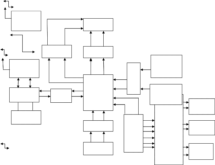
Figure 1 Block Diagram OF Wi-Fi Robot
P PORT B O
R
T
C
KEYPAD
MOTOR
T WHEELS 1
O
R
D MOTOR R WHEEL 2
I
V
E
R CAMERA
MOTOR
IJSER © 2012
The research paper published by IJSER journal is about Wi-Fi ROBOT FOR VIDEO MONITORING & SURVEILLANCE SYSTEM 3
ISSN 2229-5518
This paper presents the utilizes Wi-Fi that is specification for
wireless personal area network (a network for interconnecting the individual’s device) in which the device connection are wireless. The Atmega 32 is an 8 bit micro controller with 32 Kb in system programmable flash memory. This microcontroller is interfaced with the help of AVR studio to the system serial port tat used RS323 standards. There is a camera fixed to the robot, which transfer the video to the pc / note pad using wi- fi. The laptop is connected using Rs232 to the micro controller. There are three motor drivers which are connected to the At- mega 32, two dc motor drives are used for wheels and one to the camera. The 2 ir sensors are used in order to sense any object that comes close to it.
The H-Bridge arrangement is generally used to reverse the polarity of the motor, but can also be used to 'brake' the motor, where the motor comes to a sudden stop, as the motor's ter- minals are shorted, or to let the motor 'free run' to a stop, as the motor is effectively disconnected from the circuit. The fol- lowing table summarises operation.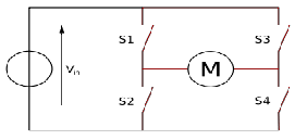
Figure 2: Structure of an H-bridge (highlighted in red)
An H-bridge is an electronic circuit which enables a voltage to be applied across a load in either direction. These circuits are often used in robotics and other applications to allow DC mo- tors to run forwards and backwards. H-bridges are available as integrated circuits, or can be built from discrete compo- nents.
The term "H-bridge" is derived from the typical graphical re- presentation of such a circuit. An H-bridge is built with four switches (solid-state or mechanical). When the switches S1 and S4 (according to the first figure) are closed (and S2 and S3 are open) a positive voltage will be applied across the motor. By opening S1 and S4 switches and closing S2 and S3 switches, this voltage is reversed, allowing reverse operation of the mo- tor.
Using the nomenclature above, the switches S1 and S2 should never be closed at the same time, as this would cause a short circuit on the input voltage source. The same applies to the switches S3 and S4. This condition is known as shoot-through.
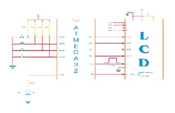
Figure 3 Interfaces between LCD And ATMEGA
The above figure shows how the lcd is connected with ATMe- ga as well as keyboard with ATMega. The port B are used for keyboard , 4 keys are used , 4 pins of port A isconnecte to LCD
2x16, one pin from port C is connected to LCD
Once this implementation is done, using a LABVIEW version
11 data and client is created to communicate between the ro-
bot and the user, person/object reorganization is done with the
help of LABVIEW, using a GPS the latitude and longitude
could be found out.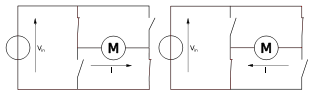
Figure 3: The Two Basic States of an H-bridge
IJSER © 2012
This robot can be used for defense purpose.
This robot could be used as spying robot.
This robot could be used in mining fields where
humans can’t go inside.
This robot can also be used in house hold security
etc…
The research paper published by IJSER journal is about Wi-Fi ROBOT FOR VIDEO MONITORING & SURVEILLANCE SYSTEM 4
ISSN 2229-5518
The size and weight of this robot is more.
GPS tracking system works only during clear sky.
Signals will be weak in deeper mining regions.
This paper presents an overview of the design, implementa- tion, testing, and performance of an innovative digital wireless remote control unit, developed for the purpose of directing the movement and operation of a robotic vehicle and displaying status feedback to the operator.
In this paper, we had proposed to design a robot which works wirelessly. The wireless method used here is Wi-Fi, using the Wi-Fi robot is controlled. The robot has a camera which sends the live video to the user, where the user will be using a LAB- VIEW to monitor the robot, as well as other objectives of this project is fulfilled. I am successful in building the circuit and implementing them on the PCB.
In this paper, we had used ATmega32 micro controller as it has advantages over 8086 micro controller. ATmega32 can perform up to 30 tasks in a single cycle. The camera will capture the picture and send it to the user. For sending and receiving, Wi- Fi is used one of the wireless method. There are 2 Wi-Fi used, one at the user side one more with the robot. The user uses LABVIEW version 11 to observe and control the robot, this v
11 has a image processing technique. There are two sensors used here, this is just to avoid the hitting to wall or any object, if the user fails to see them. There three DC motors used, one for the camera and remaining for the wheels in order to con- trol its moment, for the camera it is used just to rotate it as the user requires. Using GPS tracking system, robot could be traced +/- 50m approximately during the clear sky. Using the object recognition system, the object or face of a person could be recognized, this is done with the help of Lab VIEW.
[ 1] The Robot control using the wireless communication and the serial communication, by JONG HOON AHNN, Project Advisor: Professor Mark Campbell, Cornell University May 2007.
[ 2] Neural network and genetic algorithm based global path planning in
a static environment” by DU Xin, CHEN Hua-hua and GU Wei-kang
, VOL 6, No 6, P 549~554, 2005.
[ 3] New PC and LabVIEW based robot control system by Sandor J.
TOTH, Technical University of Budapest, Vol 43, No 2, P 179~188, June 5, 1999
[ 4] The Robot control using the wireless communication and the serial communication” By Jong Hoon Ahnn, Master of Engineering Thesis in Electrical and Computer Engineering Cornell University, 2007
[ 5] Biometric Robot Navigation” by Matthias O. Franz and Hanspeter A
Mallot.
[ 6] http://www.wpi.edu/Pubs/E-project/Available/E-project-030310
235516/unrestricted/Why_Do_Humans_Imagine_Robots.pdf
[ 7] An introduction to neural computing. Alexsander, I. and Morton, H.
2nd edition, International Thompson Computer Press, Boston, MA,
1995
IJSER © 2012