International Journal of Scientific & Engineering Research, Volume 2, Issue 2, February-2011 1
ISSN 2229-5518
Use of Frequency Modulation Technique to improve security system
Shaikh Md. Rubayiat Tousif, Shaiyek Md. Buland Taslim
Abstract— A wireless fire alarm and other passive circuit elements has been designed and implemented. The designed alarm circuit could detect any kind of smoke and generate an alarm signal that would be sent to the control room by frequency modulation technique. The designed transmitter could operate around 100 MHz. A monopole antenna has been used for transmitting the signal carrying the information in the free space. An antenna length of 41cm has been used for the design convenience. The transmitting signal has been successfully received at a distance of 53 feet without any disturbance by FM receiver. The operating frequency of the transmitter was found out to be 97 MHz and comparison shows a very good agreement between the measured value and the calculated value. The designed wireless fire alarm has been very dynamic in terms of performance and the transmitter part successfully demonstrates the basic principle of FM transmitter.
Index Terms— Frequency modulation, FM Transmitter, Monopole antenna, Range, Smoke detector
—————————— • ——————————
1 INTRODUCTION
HIS project has been designed to build a device that would detect any presence of fire and immediately send signal to the control room to take necessary ac- tions. The project also involved developing a mechanism that would allow the sensitivity and hence the power of the transmitted signal to be controlled. As a part of this project a FM transmitter has been designed that would transmit signal at a particular frequency and could be received easily with a FM receiver. Most importantly de- sign and build a cost effective wireless fire alarm that would work under any condition and be easily set up in
commercial and residential areas.
2 BASIC WORKING PRINCIPLE
The operation of a wireless fire alarm is very simple and generally follows the sequence shown on the figure. When there is a fire or smoke in the room the detector which is very sensitive quickly detects it and generates a signal or alarm which is transmitted by FM radio trans- mission and received at the control room.
A frequency generator is used to generate a frequency radio signal with a particular band range, and for mixing the frequency radio signal with the transmission data, to make a transmission signal having a particular frequency; and a transmitter for amplifying the transmission signal having the particular frequency up to a predetermined level and for transmitting the same through an antenna.
The receiver receives the transmission signal via a second antenna and filters the transmission signal to ac- quire desire data including the identification code and location data and compares the identification code with registered codes.
Fig. 1 Block Diagram of a W ireless Fire Alarm
2.1 Detection Unit
The detection unit in any kind of fire alarm circuit is the most important part. The successful operation of the circuit depends on how well this portion functions, so this portion is of great interest for the circuit designers. It should be sensitive, less complex, fast and reliable. There are various components in the smoke detection scheme where each component plays a significant role in proper functioning of the overall circuit.
————————————————
Shaiyek Md. Buland Taslim is currently pursuing masters degree program in electric power engineering in Royal Institute of Techolgy (KTH) Swe- den, PH-01913531992. E-mail: buland_taslim@yahoo.com
Shaikh Md. Rubayiat Tousif is working as a Lecturer in American Interna-
tional University-Bangladesh (AIUB), Bangladesh, PH-01913531993. E- mai:l: tousif@aiub.edu
IJSER © 2010 http://w w w .ij ser.org
International Journal of Scientific & Engineering Research, Volume 2, Issue 2, February-2011 2
ISSN 2229-5518
modulating signal) changes the instantaneous frequency of the carrier. Since the amplitude is kept constant, FM modulation is a low-noise process and provides a high quality modulation technique which is used for music and speech in hi-fidelity broadcasts. In addition to hi- fidelity radio transmission; FM techniques are used for other important consumer applications such as audio syn- thesis and recording the luminance portion of a video signal with less distortion. There are several devices that are capable of generating FM signals, such as a VCO or a reactance modulator. Frequency Modulation is abbre- viated FM.
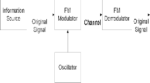
Fig. 2 Smoke Detector Circuit
Here is a simple fire alarm circuit based on a LDR and lamp pair for sensing the fire. The alarm works by sens- ing the smoke produced during fire. The circuit produces an audible alarm when the fire breaks out with smoke.
When there is no smoke the light from the bulb will be directly falling on the LDR. The LDR resistance will be low and so the voltage across it (below 0.6V).The transis- tor will be OFF and nothing happens. When there is suffi- cient smoke to mask the light from falling on LDR, the LDR resistance increases and so do the voltage across it. Now the transistor will switch to ON. This gives power to the IC1 and it outputs 5V.This powers the tone generator IC UM66 (IC2) to play music. This music will be ampli- fied by IC3 (TDA 2002).
The diode D1 and D2 in combination drops 1.4 V to give the rated voltage (3.5V) to UM66. UM 66 cannot withstand more than 4V.
Potentiometer (POT) R4 can be used to adjust the sen- sitivity of the alarm, which means turning it up towards more resistance makes the circuit less sensitive to light, while turning it down towards less resistance makes the circuit more sensitive to light. By adjusting the POT, it is possible to turn the alarm on and off just by passing sha- dow over it.
POT R3 can be used for varying the volume of the alarm. That is it can be used to control the amplifier TDA2002’s gain. This sound will be transmitted by the FM transmitter. So before being transmitted, this audio signal should be amplified to optimum level.
2.2 FM TRANSMISSION UNIT
Frequency modulation is a type of modulation where the frequency of the carrier is varied in accordance with the modulating signal. The amplitude of the carrier remains constant. The information-bearing signal (the
Fig.3 FM System Block Diagram

Fig. 4 An example of frequency modulation. This diagram shows the modulating, or message, signal, xm(t), superimposed on the carrier wave, xc (t).

Fig. 5 The modulated signal, y(t), produced from frequency- modulating xc(t) with xm(t).
IJSER © 2010 http://w w w .ijser.org
International Journal of Scientific & Engineering Research, Volume 2, Issue 2, February-2011 3
ISSN 2229-5518
2.3 FM Transmitter
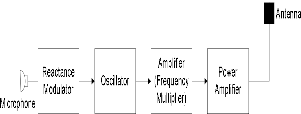
Fig. 6 General FM transmitter block diagram
In the figure the voice frequencies from the micro- phone are fed to special type of modulator called reac- tance modulator. The output of the modulator causes the frequency of oscillator to change. Output of the oscillator is amplified and the frequency is multiplied in the next section of transmitter.
Fig.7 Circuit diagram of FM transmitter
The FM transmitter’s input is the audio signal generat- ed by the alarm circuit. The first transistor Q2 works as an audio amplifier, which amplify the audio signal even more. The second transistor works as an oscillator circuit. The inductor L1 and capacitor C6 works together as an oscillator and generate a frequency in FM band. Therefore it transmits the signal at a particular frequency, which, if tuned properly will be received at the receiver. Capacitor C3 is DC blocking capacitor and C4 is coupling capacitor.
Antenna tuning is done by adjusting inductance L1 and capacitance C6 combined with the active antenna (but distinct and separate from the active antenna). The inductance and capacitance provides the reactance which combines with the inherent reactance of the active anten- na to establish a resonance in a circuit including the active antenna. The established resonance is at a frequency other than the natural electrical resonant frequency of the active antenna. Adjustment of the inductance or capacitance changes this resonance. The signal is transmitted at this resonant frequency.
2.4 FM Receiver
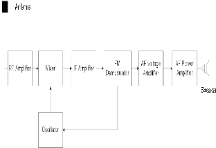
Fig.8 Block diagram of FM Receiver.
The RF amplifier selects and amplifies the desired sta- tion from the many. It is adjustable so that the selection frequency can be altered. This is called tuning. In cheaper receivers the tuning is fixed and the tuning filter is wide enough to pass all signals in the FM band. The selected frequency is applied to the mixer. The output of an oscil- lator is also applied to the mixer. The mixer and oscillator form a frequency changer circuit. The output from the mixer is the intermediate frequency (IF). The IF is a fixed frequency of 10.7 MHz. No matter what the frequency of the selected radio station is, the IF is always 10.7 MHz. The IF signal is fed into the IF amplifier. The advantage of the IF amplifier is that its frequency and bandwidth are fixed, no matter what the frequency of the incoming sig- nal is. This makes the design and operation of the am- plifier much simpler. The amplified IF signal is fed to the demodulator. This circuit recovers the audio signal and discards the RF carrier. Some of the audio is fed back to the oscillator as an automatic frequency control voltage. This ensures that the oscillator frequency is stable in spite of temperature changes. The audio signal voltage is in- creased in amplitude by a voltage amplifier. The power level is increased sufficiently to drive the loudspeaker by the power amplifier.
3 EXPERIMENTAL CALCULATIONS AND FINDINGS
3.1 Inductor
Let,
Frequency = 95MHz
Capacitance = 30pF
We know,

Resonant frequency for oscillator, Fr = 1
2TI LC
From here, using the above values for frequency and
IJSER © 2010 http://w w w .ij ser.org
International Journal of Scientific & Engineering Research, Volume 2, Issue 2, February-2011 4
ISSN 2229-5518
capacitance, inductance, L was found to be 94nH
Assuming length, l = 1cm

Total number of turns, n = L x (90 x r + 10 x l)
r2
From here, n was found to be 13 turns.
3.2 Antenna
Assuming free space propagation, C = f x A
Therefore,
10 - 1
sensor and pressure sensor can be added for better pre- diction and detection of fires.
The musical IC could be replaced by a custom made IC which will generate signal giving out the address of the particular fire affected room.
The transmitted signal can data signal transmitting time, location and origin of the fire.
Coding the signal before transmission will enhance the security, reduce multi-path fading, and allow many transmitters to use the same channel.
A speaker could be attached to the TDA2002 audio amplifier’s output for alarm to sound in the room of the fire.
/. = 3 x 10 cm.s � 316 cm
95MHz
Antenna length = A/8 = 41cm has been used for design convenience.
3.3 Practical data obtained
The transmitting frequency was found to be 97MHz. The range of the transmitter circuit was found to be
more than 53 feet on the same floor.
3.4 Antenna Designing
In our design a monopole antenna was used, though any sort of antenna such as dipole antenna could have been used in the design for signal transmission in the free space. Folded dipole antenna has high radiation imped- ance and its radiation pattern was found to be better than monopole antenna, though in practical cases monopole antenna is used for FM transmission. We have chosen antenna length to be A/8, which is almost 41cm.
3.5 Range of the circuit
The range of the transmitter circuit was determined by placing the receiver at different distances up to which the audio signal is clearly heard. The range was found to be more than 50 feet on the same floor. The signal could not be received clearly at different floor from the transmitter as harmonics effect there was too strong. The received power reduces with the increment in distance as ex- pected. The range was found to be more at night and the sound quality of the signal was better too. This was due to less amount of electrical equipment working at night reducing the overall interference.
3.6 Suggestions for Future Work
Design improvements that could be considered in fu- ture are listed bellow:
More sensors, such as temperature sensor, humidity
4. CONCLUSION
Wireless fire alarm is a very effective safety device, its application and use have been increasing day by day and in most cases radio transmission is used to send the sig- nal. FM is used because of its superiority over other ana- log modulation schemes such as AM and PM. It shows good sound quality, better reception and more immune to noise and signal distortion. This project included a two transistor low power FM transmitter which gave us the opportunity to learn precisely the basic principle of fre- quency modulation, transmitter circuit, and various its components. While designing the smoke or fire detector we learnt the various methods by which smoke or fire is detected and different components in the fire alarm cir- cuit were discussed extensively as well.
ACKNOWLEDGMENT
We would like to thank all our group members for the help and support.
REFERENCES
[1] B.P. Lathi, “Modern Digital and Analog Communication Sys- tems”, 3rd Edition, Oxford University Press, New York, pp. 1-
13, 151-189, 208-245.
[2] Simon Ramo, J.R Whinnery and T. Duzer, “Fields and Waves in Communication Electronics”, 2nd Edition, John Wiley and Sons, pp. 634-680.
[3] V.K. Mehta, “Principles of Electronics”, 3rd Edition, pp.386-
406.
[4] J. Millman, Christos C. Halkias, “Integrated Electronics”, Sixth reprint 1994, Tata McGraw-Hill Edition, pp. 118-152,
223-280, 348-368, 483-497.
[5] Robert L. Boylestad, Luis Nasheisky, “Electronic Devices and
Circuit Theory”, 8th Edition, Prentice-Hall of India, pp. 131-
189, 355-426, 747-782, 821-850.
[6] Samuel Y. Liao, “Microwave Devices and Circuits”, 3rd Edi- tion, Prentice-Hall, pp. 21-56.
IJSER © 2010 http://w w w .ijser.org