International Journal of Scientific & Engineering Research, Volume 6, Issue 4, April-2015 14
ISSN 2229-5518
Unique Shaped Structures: Modelling, Design and Verification of a Water Drop-Shaped Building Anthony Nkem Ede1 and Edidiong Godwin Udoh2
Abstract— Unique shaped structures have been of great interest to the world for the way they impact the environments. Their points of location become centres of attraction for residents and visitors alike. This has brought a lot of joy, love and benefits to the host cities. The inkling of water drop-shaped structure came as a contribution towards increasing the number of existing iconic master pieces. This work will consist of creating structural model, analysing and designing the elements in reinforced concrete and glass in accordanc e to the British Standards. The research will mark an advancement on previous models on bottle-shaped structures. The non-symmetric circular shaped structure is modelled floor by floor to take care of the irregular change of shape vertically and horizontally. Prevailing and the most grievous load combinations are adopted for the non-linear finite element analysis. All the elements passed the structural verification tests and the drifts were within limits for various combination of loads.
Index Terms—Bottle-Shaped Structure, Design, Iconic Building, Reinforced Concrete, Structural Analysis, Verification, Water Drop.
1 INTRODUCTION
—————————— ——————————
Unique shaped structures has been of great importance to the host cities as it impacts positively on their economic fortune and put them in the mind of many people [1]. An iconic struc- ture is defined as an architectural masterpiece that is beautiful in form and serves a useful purpose to the society [2]. The World have seen many of them and will still be glad to see more of them as they normally catch the imagination of visi- tors and leave impressive memories in their minds. Foremost among such structures include the tower of Pisa, Paris’s Eiffel Tower, the Sydney Opera House, the Burj Al Arab of Dubai, the Beijing National stadium, Torre Agbar of Barcelona and 30
St Mary Axe of London to mention a few. Standing on the
shoulders of previous circular or skewed shaped structure such as Burj Al Arab of Dubai, Torre Agbar of Barcelona, 30 St Mary Axe of London, Adegbayi’ bottle shaped structural model of 2009 [3], Udoh’s innovative bottle shaped structural model of 2012 [4] and the most recent Ede and Udoh’s model of 2015 [1], this skewed-shaped structure is created to add joy to the sight of the World. The research creates the quasi- circular shaped structure by modelling each floor separately to take care of the skewed shape of a water drop and to accom- modate the irregular change of shape vertically. This structure in the shape of a water drop is to be constructed in reinforced concrete based on British Standards [5], [6], [7]. The building stands at a height of 56m from the ground level with 11 floors above the ground and will serve as a hotel facility.
————————————————
• 1PhD, Senior Lecturer, Depart of Civil Engineering, Covenant University, Canaan Land, Km 10, Idiroko Road, P.M.B. 1023 Ota, Ogun state, Nige- ria. anthony.ede@covenantuniverity.edu.ng
• 2Student, Depart of Civil Engineering, Covenant University,
This unique-shaped building will improve any host city where
it will be built. The modelling consist of the floor by floor crea- tion of the architectural model through AutoCAD 2012 and ArchiCAD 15, structural analyses, design and verifications of the water drop-shaped building using Orion R16. In this re- search, the problematics of high rise building design [6] were put into considerations.
2 LITERATURE REVIEW
An iconic structure is considered as an architectural master- piece and the design process will require some extra feats when compare to a conventional building structure. Concep- tually, a building structure is an assembly of structural ele- ments that are subjected to various kind of stresses. The de- sign process starts with the creation of a floor plans and the structural frame, followed by structural analysis to determine the effects of design loads on the elements in terms member stresses, then comes the arrangement and proportioning of the members such that they will resist the design stresses within the allowable limit states and then followed again by verifica- tion analysis to confirm the suitability of the selected sections for the member stresses. Details of various approaches of analysis and design can be found in [9], [10], [11], [12], [13]. For a unique shaped structure such as the one under consider- ation, the basic concepts of structural frame creation, structur- al analysis, design and verification analysis remain valid, though strict consideration of the irregular characteristics of the iconic structure in every phase of the design process is indispensable. For this, the water drop shaped structure’s asymmetrical characteristics include non-uniform circular widths along the height and the skewed shape that causes the centre of gravity of the building not to be centrally placed must be considered in every phase. This requires a great
IJSER © 2015 http://www.ijser.org
International Journal of Scientific & Engineering Research, Volume 6, Issue 4, April-2015 15
ISSN 2229-5518
strictness in creating a model that conforms to the shape of water drop and at the same time contribute to the overall sta- bility of the building. For this, previous curvilinear shaped or skewed shaped structures such Burj Al Arab, Torre Agbar, 30
St Mary Axe, Adegbayi’ bottle shaped structural model of
2009, Udoh’s innovative bottle shaped structural model of
2012 and the most recent Ede and Udoh’s bottle shaped model of 2015 were all useful for this research. After understudying these models, the characteristics they share in common with water drop shaped structure were judiciously embedded in the design of this structure. The structure is to be realized in reinforced concrete material because that is the most common material used in Nigeria and for which the basic technology of application is locally available. Reinforced concrete is a strong durable composite material per excellence [14] and can be easily used to obtain the vertically and horizontally varying shape of a water drop shaped building. In fact, complex struc- tures such as Burj Al Arab and Torre Agbar were realized in reinforced concrete.
3 METHODOLOGY
Here, the steps adopted for the floor by floor modelling, struc- tural analysis and design are considered. The water drop im- age was imported into AutoCAD 2013 and scaled to the de- sired height of the structure. The dimensions obtained were used to create the architectural models. Based on these mod-
els, structural analysis and design were carried out.
3.1 Super Structures Dimensions
Approaches used on the various versions of the bottle shaped buildings [3], [4], [5] were readily applied to this water drop shaped structure. An image of the water drop was imported into AutoCAD and measurement taken. Diameters of the floors were taken to correspond to varying diameters at differ- ent heights. There are nine useable floors with two additional floors just for the realization of the water drop shape of the building.
The 3D structural model was first created in AutoCAD and then simulated in Orion R16 software. The structure’s shear wall in the core which acts as the elevator shaft and also encir- cled by the stairs was modelled to give stability to the skewed shape of water drop shaped building.
3.2 Analysis and Design
The analysis of the model was carried out with Orion R16. Non-linear finite element analysis was performed on the slabs of varying shapes, beams, columns and walls, obtaining bend- ing moments and shear stresses. The design was performed by Orion R16 in accordance with British Standards. The typical member sizes for each floor are tabulated in table 1. Various models of bottle shaped structures [1] that were useful for this research are shown in figure 1 while table 2 contains the struc- ture’s storey heights and floor widths information.
Figure 2 shows the ultimate model of the bottle shaped model.
Table 1: Typical member sizes
STOREY STOREY HEIGHT
(m)
SLAB DEPTH
(mm)
PRIMARY BEAMS
(mm)
PERIMETER BEAMS (mm)
COLUMN DIAMETER
(mm)
WALL THICK- NESS (mm)
0 4.00 200 225×750 150×500 500 300


1 4.00 200 225×750 150×500 500 300
2 4.00 200 225×750 150×500 500 300

3 4.00 200 225×750 150×500 500 300
4 4.00 200 225×750 150×500 500 300

5 4.00 200 225×750 150×500 500 300
6 4.00 200 225×750 150×500 500 300

7 4.00 200 225×750 150×500 500 300
8 4.00 200 225×750 150×500 500 300

9 4.00 200 225×750 150×500 500 300
10 4.00 200 225×750 150×500 500 300
IJSER © 2015 http://www.ijser.org
International Journal of Scientific & Engineering Research, Volume 6, Issue 4, April-2015 16

ISSN 2229-5518
12 4.00 200 225×750 150×500 500 300
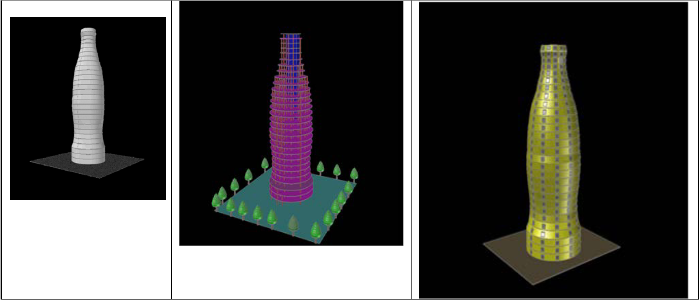

Figure 1: Various models bottle shaped arranged in growing order sophistication (Source: [1]).
Table 2: storey height and floor width information
STORY | PROGRESSIVE HEIGHT (m) | FLOOR WIDTH (m) |
| | |
0 | 0.00 | 11.40 |
1 | 4.00 | 20.1 |
2 | 8.00 | 25.9 |
3 | 12.00 | 27.8 |
4 | 16.00 | 27.4 |
5 | 20.00 | 25.8 |
6 | 24.00 | 22.5 |
7 | 28.00 | 19.1 |
8 | 32.00 | 15.00 |
9 | 36.00 | 10.6 |
10 | 40.00 | 6.4 |
11 | 44.00 | 4.00 |
Pinnacle | 56.00 | Not Applicable |
4 RESULTS AND DISCUSSION
This section presents the result of the work carried out in the actualization of the water drop shaped structure. The works consisted of floor plan and structural frame modelling, struc- tural analysis, design and verifications. The modelling was
particularly intricate of the floor per floor size variability and the skewed shape of water drop shape. Figure 3 shows a water drop image while figure 4 contains the segmented image of a water drop with all the dimensions indicated.
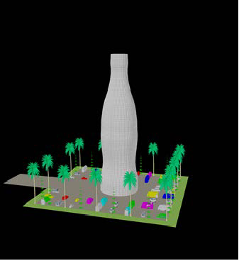
Figure 2: shows the ultimate model of the bottle shaped model that served as precursor this research (Source: [1]).
IJSER © 2015 http://www.ijser.org
International Journal of Scientific & Engineering Research, Volume 6, Issue 4, April-2015 17
ISSN 2229-5518
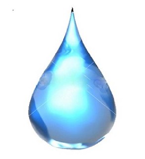
Figure 3: A water drop image
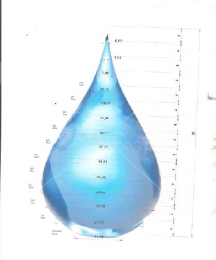
Figure 4: Segmented image of a water drop with vertical and hor- izontal dimensions.
From the segmented image of a water drop, the floor plans were developed based on the diameters obtained on the seg- mented image. Once the floor plans were ready, the structural
frame was built adhering to the heights identified in the seg-
mented image. Various structural models were created in search of the most correct model that will respect the skewed shape of water drop and guarantee stability to the structure. Then the structural analysis and design were carried out using Orion R16 considering several load cases. Figures 5 to 7 show a typical floor plan and different models of structural frames obtained before structural analysis and design were per- formed.
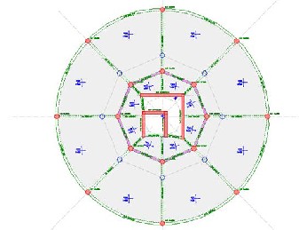
Figure 5: A typical floor of the Water Drop shaped building
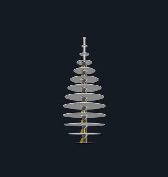
Figure 6: shows a model of the slabs, stairs and the core.
IJSER © 2015 http://www.ijser.org
International Journal of Scientific & Engineering Research, Volume 6, Issue 4, April-2015 18
ISSN 2229-5518
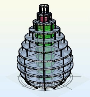
Figure 7: shows the complete model of the water drop shaped structural frame realized with Orion R16.
A look the structural models shows the true shape of a water drop image have been simulated as the structural system con- forms to the water drop image. The models show the position of the structural members. The load transfer system is such that
the shear walls carry part of the load while the other members carry some of the load such that over reliance on the core walls for load transfer is avoided.
This is to guarantee that the failure of one element does not bring down the whole structure. The final model of figure 8 shows a realistic rendered picture of the water drop shaped building structure. This shows that the research was successful as the water drop shaped building was effectively created, modelled, analysed, designed and verified. This is an indication that the structure can be effectively constructed and that a new iconic structure is born for the World. However, various form of difficulties were encountered in the modelling process. Limited examples of curvilinear shaped or skewed shaped structures to follow after was a problem. The asymmetric shape and dissimi- lar floors were added difficulties. Then follows the difficulties of the soft wares modelling irregular shaped structures.
5 CONCLUSION
The aims of the research were achieved as a new unique shaped building design has been proposed and effectively modelled, analysed, designed and verified using AutoCAD and Orion soft wares. The most stressed members on the ground floor were effectively verified to confirm the validity of the simulation ap- proach adopted. The lateral drifts of each floor is within ac- ceptable limits. The water drop shaped building will place host city on the World map and boast the tourism of the city. It is believed that this research project will inspire more re- searchers to put their reasoning to work and come out with many creative works that will make the world more beautiful.
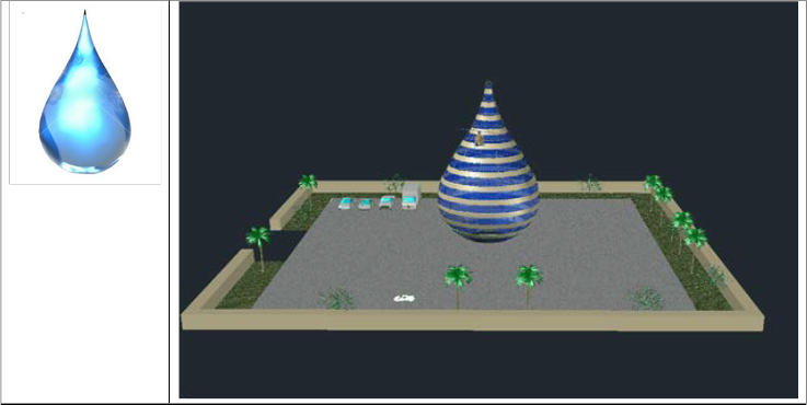
Figure 8: shows the rendered view of a water drop-shaped building structure model
IJSER © 2015 http://www.ijser.org
International Journal of Scientific & Engineering Research, Volume 6, Issue 4, April-2015 19
ISSN 2229-5518
ACKNOWLEDGMENT
The authors wish to thank the Chancellor and the Manage- ment of Covenant University for the platform made available for this research
REFERENCE
[1] Ede, A.N. and Udoh, E.G. (2015). “Modelling, Analysis and Design of a Bottle- Shaped Building”, IISTE Civil and Environmental Research, in press.
[2] Etheridge, J. (2007). Bling Bling Architecture: Iconic Buildings to Remake Kuwait. Retrieved January 22, 2013, from http://www.kuwaittimes.net/read_news.php?newsid=NTM5MjM5NjU4
[3] Adegbayi, A.O. (2009). “Structural Analysis and Design of Unique Shaped Structure: Case Study of a Bottle Shaped Structure”, Unpublished final year student project, Department of Civil Engineering, Covenant University, Ota, Nigeria.
[4] Udoh, E.G. (2013). “Unique Shaped Structures: a Case Study of a Water Drop Shaped Building”, Unpublished final year student project, Department of Civil Engineering, Covenant University, Ota, Nigeria.
[5] BS 8110-1, Structural use of concrete — Part 1: Code of practice for design and
construction, 1997.
[6] BS 6399-1: 1996: Loading for buildings – Part 1: Code of practice for dead and imposed loads. London: BSI, 1996.
[7] BS 6399-2: 1997: Loading for buildings – Part 2: Code of practice for wind loads. London: BSI, 1997.
[8] Ede, A.N., Challenges Affecting the Development and Optimal Use of Tall Buildings in Nigeria, The International Journal Of Engineering And Science (IJES), 3(4), Pages 12-20, 2014.
[9] Wai-Fah Chen and Eric M. Lui. (1999). Hand Book of Structural Engineering.
Boca Raton: CRC Press.
[10] Arya, C. Design of Structural Elements: Concrete, Steelwork, Masonry, and Timber Designs to British Standards and Euro codes, (3rd Edition; Taylor & Francis, London, 2009).
[11] Chen, W. The Civil Engineering Handbook, Published by CRC Press LLC;
2nd Edition; Boca Raton (1999).
[12] MacGinley, T.J. Choo, B.S. Reinforced Concrete Design; Published by E &FN Spon; 2nd Edition; London, (1990).
[13] Mosley, W.H. Reinforced Concrete Design- Theory and. Chapman & Hall
Inc: London, (1999).
[14] Ede, A.N., Agbede, J.O. (2015). Use of Coconut Husk Fibre for Improved Compressive and Flexural Strength of Concrete, International Journal of Sci- entific and Engineering Research, 6(2), pp. 968-974.
IJSER © 2015 http://www.ijser.org