International Journal of Scientific & Engineering Research Volume 2, Issue 7, July-2011 1
ISSN 2229-5518
Underwater Acoustic Networks
G.Divya, Varshitha Prakash
Abstract— With the advances in acoustic modem technology that enabled high-rate reliable communications, current research focuses on communication between various remote instruments with in a network environment. Underwater acoustic (UWA) are generally formed by acoustically connected ocean-bottom sensors, autonomous under water vehicles, and a surface station which provides a link to on-shore control center. Underwater Acoustic networks (UANs) are very unique and can be deployed for commercial and military applications. The research of UANs attracts increasing attention in recent years. This survey paper first introduces the concept of UANs and also focus on some practical and potential research issues of UANs, ranging from energy saving and deployment to different layers. Suggestions and solu- tions for these issues are listed.
Index Terms— Underwater Acoustic Networks, under water Acoustic communications, Energy Efficiency, Medium Access
Control, Cross layer Design.
1 INTRODUCTION
—————————— • ——————————
HE earth is a water planet covering about two thirds of the surface of the earth. Compared with our hu- man being’s with land, there are still many un-
explored areas in underwater. This needs significant re- search efforts in under water.
The research of Underwater Acoustic Networks (UANs) is attracting attention due to their important un- derwater applications for military and commercial pur- poses. The applications of UANs include:
• The primary goal of communication networks is ex- change of information. In an UAN, exchanging Informa- tion among nodes is one of its essential applications. An example is that underwater Internet,
in which users can share information without tether, if
UANs are deployed. Another important application
is real-time communication with submarines and auto-
nomous underwater vehicles in network configurations .
• Environmental monitoring. Pollution in near-shore
oceans is raising alarms in recent years and this needs a
close watch. UANs can be used to perform different kinds
of pollution monitoring, e.g., chemical, biological, nuc-
lear, and oil leakage pollutions in bays, lakes, or rivers.
UANs can also be used to monitor ocean temperature
change, e.g., the global warming effect to ocean.
• Underwater explorations. Underwater explorations can be easily done by UANs as it is difficult for human beings due to the high water pressure and unpredictable under- water activities. UANs can help in detecting minerals,
oilfields and also determines routes for laying undersea cables.
• Disaster prevention. By deploying Acoustic Sensor Networks in remote locations, the different undersea ac- tivities such as ocean-related disaster like tsunami and seaquake can be can be easily monitored and warned to coastal areas in real time.
• Assisted navigation. An UAN can identify hazards on the seabed; locate dangerous rocks in shallow waters and submerged wrecks by using acoustic sensors.
Underwater Acoustic Sensor Networks (UASNs) [1] and Autonomous Underwater Vehicle Networks (AUVNs) [2] are defined as networks composed of more than two nodes using acoustic signal to communicate, for the purpose of underwater applications.
The research of UANs becomes different in communication system aspect, as the communication in underwater environment is different from its ground- based counterpart. But it exhibits certain unique features. It is because:
1) In underwater environment acoustic signal works bet- ter than any other signal. Compared with it, electromag- netic wave is the only one that can travel in water with short distance due to the high attenuation and absorption effect in underwater environment. The absorption of elec- tromagnetic energy in sea water is about 45× -Jf dB per kilometer, where f is frequency in Hertz.
2) The other type of signal is optical signal which is strongly scattered and absorbed in underwater environ- ment. But there are some investigations going on about utilizing optical signal for underwater applications. How- ever, the optical signal can not be used for long distance transmission as it can only pass through limited range in very clean water environment (deep water, for example).
In these networks exchanging of information from one point to another is done by using Acoustic signal. The Acoustic signals required for UANs are generated by so- nar. The main advantage of using Acoustic signal in UAN is to extract information in the presence noise and uncer- tainty.
2 DESIGN CHALLENGES IN THE UANS
Under Water Acoustic Networks is a new research area and there are many unsolved issues. An underwater acoustic channel is different from a ground-based radio channel from many aspects, including:
1) The available bandwidth is extremely limited. The at-
IJSER © 2011 http://www.ijser.org
International Journal of Scientific & Engineering Research Volume 2, Issue 7, July-2011 2
ISSN 2229-5518
tenuation of acoustic signal increases with frequency and range [3] [4] [5]. Consequently, the feasible band is ex- tremely small. For example, a short range system operat- ing over several tens of meters may have available band- width of a hundred kHz; a medium-range system operat- ing over several kilometers has a bandwidth on the order of ten kHz; and a long-range system operating over sev- eral tens of kilometers is limited to only a few kHz of bandwidth.
2) Propagation delay is long. The transmission speed of acoustic signals in salty water is around 1500 meter/s [6], which has a difference of five orders of magnitude lower than the speed of electromagnetic wave in free space. Correspondently, propagation delay in an underwater channel becomes significant. This is one of the essential characteristics of underwater channels.
3) Due to extreme characteristics of the channel, probabili- ty of bit error is much higher and temporary loss of con- nectivity also occurs.
The design of UANs faces some special challenges: Firstly, for the underwater equipments the cost of manu- facturing, deployment, maintenance and recovery is much higher than that of the ground-based counterpart. Secondly, one of the critical issues for UAN is saving energy. UANs are usually designed in such a way that they can work properly in underwater as long as possible because of the high cost of re-deploying underwater equipment. So saving energy is taken into consideration to make equipments run longer in Underwater Networks. Thirdly, due to fouling and corrosion from the hostile underwater environment the underwater equipments can easily be damaged. So it impacts on the operational life of an UAN and this should be taken into consideration.
3 ISSUES OF UAN RESEARCH
4 The different issues in UAN research are network to- pology, physical layer, MAC layer, Network layer, and Application layer.
3.1 Network topology
The Network topology of UAN network is different from that of its ground-based counterparts due to the uniqueness of underwater channels and characteristics of acoustic signal. However, the fundamental design goals are the same, i.e., providing reliable connectivity among nodes in the network; increasing network capacity; and minimize the energy consumption.
Network topology is nothing but a layout pattern of interconnections of various elements. Basically, two types of network topologies can be used: ad hoc mode and hie- rarchy mode. In the former one, nodes are self-organized as a peer-to-peer network, as shown in Fig 1. Peer-to-peer topology can be further divided into point-to-point con-
nection topology, and multi-hop connection one. There is just one hop from a node to any other node in the first type of connection, i.e., routing is not necessary. In the latter one, other nodes are involved to relay a data mes- sage from a source node to its destination. In other words, routing is needed with this second type of network topol- ogy.
Fig 1. An example of peer-to-peer topology
Fig 2. Shows an example of hierarchy network topology in which several levels of the structure are deployed.
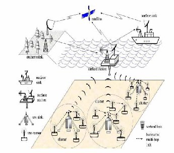
Fig 2. An example of Hierarchy topology.
3.2 Physical layer
The physical layer consists of the basic hardware transmission technologies of a network. It is the physical channel that makes UAN unique. The characteristics of underwater channels are described in. As discussed in before, in an underwater channel the electromagnetic wave band have high attenuation, but only a small part of
IJSER © 2011 http://www.ijser.org
International Journal of Scientific & Engineering Research Volume 2, Issue 7, July-2011 3
ISSN 2229-5518
long-wave band could go through it with relative less attenuation. For example, 1-8 kbits/sec at 122 kHz ranges up to 6-10 m. However, both large antenna and high transmitter powers are required. The absorption of the optical signal is high and badly gets scattered in under- water. Beside of these, optical wave transmission requires high precision in pointing the narrow laser beams.
The only practical solution for underwater com- munication with acceptable range is using acoustic signal, which travels in underwater with longer distance, less attenuation, and higher reliability.
However, for acoustic signal the available bandwidth is extremely limited. Similar to other kinds of signal wave- forms acoustic signal in underwater environment, en- counters attenuation which increases with increase in the frequency, as shown in Fig. 3. Compared with the speed of electromagnetic wave, acoustic signal travels much slower in salty water (approximately 1500m/s, which is
2x10⁵ lower than the electromagnetic wave) [6].
Fig 3. Absorption rate of acoustic signal undersea
3.3 MAC Layer
The MAC layer is responsible for moving data packets from one layer to another. The underwater nodes in an UAN have to share available resources due to the ex- tremely-limited-bandwidth, relatively long propagation delay and high-bit-error-ratio nature of underwater acoustic channels. Medium Access Control layer controls the nodes in an UAN to access the underwater acoustic channel. It allocates resources and schedules each node to access the physical medium. From the network’s aspect, MAC layer plays a critical role in the whole system’s op- eration, resource allocation, and ensuring the Qualify of Service (QoS). The physical layer tries to optimize the performance with current channel condition and availa-
ble resource, e.g., bandwidth. However, the MAC layer is responsible to determine the resource that physical layer could have and set up some of physical layer’s parame- ters accordingly.
3.4 Network Layer
The network layer determines the path from a source node to destination one. The network layer is responsible for routing packets delivery including routing through intermediate routers. There are two types of routing me- thods. The first one is virtual circuit routing and another one is packet-switch routing.
In virtual circuit routing, the networks use virtual cir- cuits to decide on the path at the beginning of the net- work operation. Where as in packet-switch routing, every node that is part of the transmission makes its own routing decision, i.e., decides its next hop to relay the packet. Packet-switch routing can be further classified into proactive routing and reactive routing protocols. Most routing protocols for ground-based wireless net- works are packet-switch based.
Proactive routing protocols attempt to minimize the message latency by maintaining up-to-date routing in- formation at all times from each node to any other node. In order to maintain correct route information, a node must periodically send control messages. Proactive routing broadcasts control packets that contain routing table information. Typical protocols include Destination Sequence Distance Vector (DSDV) [7] and Temporally Ordered Routing Algorithm (TORA) [8].
Reactive routing protocols are used to initiate a route discovery process upon request. These types of pro- tocols reduce routing overhead because they do not need to search for and maintain the routes on which there is no data traffic. So these kind of routing protocols are more suitable for dynamic environment like ad hoc wireless networks [9] [10].
Typical protocol examples are Ad hoc On-demand Dis- tance Vector (AODV) [11] and Dynamic Source Routing (DSR) [12].
Virtual-circuit-switch routing protocols can be a better choice for underwater acoustic networks. The reasons are:
1)Virtual-circuit-switch routing protocols work robust against link failure, which is critical in underwater envi- ronment; and
2)Virtual-circuit-switch routing protocols have less signal overhead and low latency, which are needed for under- water acoustic channel environment.
3.5 Application Layer
The purpose of application layer is to provide a net- work management protocol that makes hardware and software detail of the lower layers transparent to man- agement applications. This layer handles different issues
IJSER © 2011 http://www.ijser.org
International Journal of Scientific & Engineering Research Volume 2, Issue 7, July-2011 4
ISSN 2229-5518
like resource allocation and problem partitioning. The different functionalities are:
1) Identifying communication partners.
2) Determining resource availability.
3) Synchronizing communications.
Some examples of application layer protocols for
ground-based wireless networks are Telnet, File Trans-
port Protocol (FTP), and Simple Mail Transfer Protocol
(SMTP).
4 Proposed Solutions
To improve network efficiency, cross-layer ap- proaches are proposed for ground-based wireless net- works. In this kind of mechanism, to overcome the disad- vantage of lack of sharing information among different layers a joint design of different network functionalities, e.g., from modem design to MAC protocols, from channel coding to routing methods, is enabled.
An UAN should have the capacity to adjust itself to the changing environment due to the economic concern and complex environment of underwater. Correspon- dently, the topology and protocol design should be able to self-adaptive, if environment changes. Energy efficien- cy is critical issue to UANs life and normal operation. So the protocol design of an UAN should always be taken in to consideration.
5 Simulation
One fundamental problem in Underwater Sensor Networks (UWSNs): robust, scalable and energy efficient routing. UWSNs are significantly different from terrestri- al sensor networks in the following aspects: low band- width, high latency, node float mobility (resulting in high network dynamics), high error probability, and 3- dimensional space. These new features bring many chal- lenges to the network protocol design of UWSNs.
A novel routing protocol, called vector-based for- warding (VBF), aiming to provide robust, scalable and energy efficient routing. VBF is essentially a location based routing approach. No state information is required on the sensor nodes and only a small fraction of the nodes are involved in routing. Moreover, packets are forwarded in redundant and interleaved paths, which add robust- ness to VBF. Further, we develop a localized and distri- buted self-adaptation algorithm, which helps to enhance the performance of VBF.
The self-adaptation algorithm allows the nodes to weigh the benefit to forward packets and reduce energy consumption by discarding the low benefit packets. We evaluate the performance of VBF through extensive simu- lations. Our experiment results show that for networks with small or medium node mobility (1 m/s-3 m/s), VBF
can effectively accomplish the goals of robustness, energy efficiency, and high success of data delivery.
6 Performance Evaluation
To evaluate the performance of VBF through extensive simulations in NS-2, we first brief our im- plementation of MAC protocol, then define the per- formance metrics and describe the simulation metho- dology. We evaluate how network parameters such as node density, node mobility, and routing pipe ra- dius, affect the performance of VBF.
6.1 Implementation of MAC Protocol
VBF is a routing protocol, and medium access is not its concern. However, its performance can be signif- icantly affectedbythe underlying MAC protocol.
To evaluate the performance of VBF, we imple- ment a simple MAC protocol based on CSMA. In this MAC protocol, only broadcast is supported. When a sender has packets to send, it first senses the channel. If the channel is free, it broadcasts its packets. If the channel is busy, it uses a back-off algorithm to contend the channel. The maximum number of back-offs is 4. In this protocol, there is no collision detection, no RTS/CTS, and no ACK.
In our experiments, we measure packet delivery ratio, energy consumption and end-to-end delay achieved by VBF.
In order to reduce the collision and interference among neighbor nodes, each sender randomly delays its send- ing time in VBF. The data rate for MAC protocol is set to 500 kbps, and the propagation speed of acoustic signals is set 1500 m/s.
6.2 Metrices and Methodology
The three metrics to quantify the performance of VBF: success rate, energy consumption and average delay. The success rate is the ratio of the number of packets successfully received by the sink to the num- ber of packets generated by the source. The communi- cation time is the total time spent in communication of sensor networks in the simulation including transmission
time and receiving time of all nodes in n e t w o r k s . The
average delay is the average end-to-end delay for each
packet received by the sink. Even though the actual av-
erage delay is determined by many factors such as me-
dium contention, collision detection and avoidance
(which we do not address in this paper) and absolute
values are not very meaningful, it is useful metric to
evaluate a routing protocol when a comparison is per-
formed.
6.3 Impact of the Routing Pipe Radius
The impact of the routing pipe radius (i.e., the dis-
IJSER © 2011 http://www.ijser.org
International Journal of Scientific & Engineering Research Volume 2, Issue 7, July-2011 5
ISSN 2229-5518
tance threshold) in this set of simulations. There are 500 nodes in the network, and their speed is fixed at 3m/s. We vary the radius from 0 meters to 600 meters. When the speed is fixed at 0m/s to 3m/s, the no. of nodes are varied. The results are shown in Fig’s 4 and 5
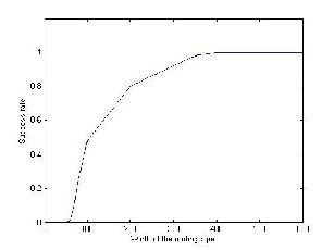
Fig 4: Success rate vs. routing pipe radius
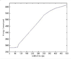
Fig 5: Width of the pipe vs Energy Consumed
7 Conclusion and Future work
In this paper, we have proposed a vector-based forwarding (VBF) protocol to address the routing chal- lenges in UWSNs. VBF is scalable, robust and energy effi- cient:
1) Packets carry routing related information and no state information is required at nodes. Thus, it is scalable in terms of network size;
2) In VBF, only those nodes close to the routing vector are involved in data forwarding. Therefore, it is energy efficient. Moreover, our self-adaptation algorithm allows a node to estimate its importance in its neighborhood and thus adjust its forwarding policy to save more energy;
3) VBF utilizes path redundancy (controlled by the routing pipe radius) to provide robustness against packet loss and node failure. Our simulation results have dem- onstrated the promising performance of VBF.
Future Work
There are several directions in UWSNs worth fu- ture investigation. 1) In the VBF simulations, a simple MAC protocol as the underlying link layer protocol is used. This is not a satisfactory choice. Designing an effi- cient MAC protocol for underwater sensor networks is desirable for the next step. 2) To study the reliable data transfer and congestion control problems, which are very challenging due to the unique features of UWSNs: high end-to-end delay, low bandwidth, and high error proba- bility.
REFERENCES
[1] I. F. Akyildiz, D. Pompili, and T. Melodia, “Underwa- ter acoustic sensor networks: research challenges”, Ad Hoc Networks (Elsevier), vol. 3, no. 3, pp. 257-279, March
2005.
[2] H. Schmidt, “Autonomous underwater vehicle net-
works as integrated acoustic observation systems”,
Acoustical Society of America Journal, Vol. 117, Iss. 4, pp.
2409 – 2410, April, 2005.
[3] L. Berkhovskikh and Y. Lysanov, Fundamentals of
Ocean Acoustics”. New York: Springer, 1982.
[4] A. Quazi and W. Konrad, “Underwater acoustic
communications,” IEEE Communication. Mag., pp. 24–29,
Mar. 1982.
[5] R. Coates, “Underwater Acoustic Systems”, New
York: Wiley, 1989.
[6] R. J. Urick, “Principles of Underwater Sound”, 3rd
Edition, McGraw-Hill Publishing Company, New York,
NY, 1983.
[7] F. Schill, U.R. Zimmer, and J. Trumpf, “Visible Spec-
trum Optical Communication and Distance Sensing for
Underwater Applications”, In Proc. Australasian Conf. Ro-
botics and Automation, Canberra, Australia, Dec., 2004.
[8] C. E. Perkins and P. Bhagwat, “Highly dynamic desti-
nation sequence distance vector routing (DSDV) for mo-
bile computers,” in Proc. SIGCOMM’94, Aug. 1994, pp.
234-244, London, UK.
[9] C. Zhang, M. C. Zhou, and M. Yu, “Ad hoc Network
Routing and Security: A Review,” International Journal of
Communication Systems, Vol. 20, pp. 909-925, Aug. 2007.
[10] Z. Wang, L. Liu and M. C. Zhou, “An Epidemic
Routing Strategy for Vehicular Ad Hoc Wireless Net-
works in Intelligent Transportation Systems,” Internation-
al Journal of Intelligent Control and Systems, Vol. 10, No. 1,
86-93, March 2005.
[11] D. B. Johnson and D. A. Maltz, “Protocols for adap-
tive wireless and mobile networking,” IEEE Personal
Communication., pp. 34 – 41, April, 1996.
IJSER © 2011 http://www.ijser.org
International Journal of Scientific & Engineering Research Volume 2, Issue 7, July-2011 6
ISSN 222S-5518
[12] C. E. Perkins, E. M. Belding-Royer and S. Das, "Ad Hoc On Demand Distance Vector (AODV) Routing," IETF Experimental RFC,Jul. 20CB.
IJSER 2011 http/lwww .qser.org