International Journal of Scientific & Engineering Research Volume 2, Issue 7, July-2011 1
ISSN 2229-5518
Tribological Material Selection, Analysis
Modification and Manufacturing of Mill Roller of 4-High Rolling Mill with FEA Model
Prasad Sane, Dr. Ashesh Tiwari
Abstract— In the industry, mill rollers are undergoing severe loading for 24 hours 7 days a week which results in formation of crack due to loading conditions, temperature and stress intensity. This leads to the demand in material selection according to its tribological needs which make the existing material to last for more time than the existing. Failures of rolls occur due to improper manufacturing and operational para- meters. The samples of prematurely failed roll samples collected from steel plant were examined for their chemistry, inclusion content, micro- structures, carbide characteristics, hardness and the retained austenite content. The residual stresses were also measured on the inner as well as the outer surface of the spalled roll pieces. The results obtained have been discussed in this paper. The higher content of retained austenite was primarily responsible for the spalling of indigenous rolls for which sub zero treatment has been recommended. Several sugges- tions have also been made for smooth operation of the mill and consequently for the extension of life of a work roll [1]. A procedure is de- scribed for the calculation of stress intensity factors for surface cracks in a section roll. Results are given in terms of the load acting of the roll and the average pressure acting on the roll/work piece interface. It is noted that the load acting on the roll can be determined for individual cases by experimentally measuring the deformation of the roll stands: this obviates the necessity of relying on theoretical estimates of the roll/work piece pressure. The stresses in the uncracked roll are determined using an axis symmetric finite element model. However, for the subsequent calculations of stress intensity factors the analysis is reduced to a plane strain model. It is shown that it is necessary to carry out finite element stress analysis on cracked rolls to determine stress intensity factors and to find the point of crack initiation and crack propaga- tion [2].
Index Terms— Finite Element Analysis (FEA), Optimization, LEFM, Life Prediction of Roll, Finite Element Model, Feasiblity, crack initiation, crack propagation.
1. INTRODUCTION
—————————— • ——————————
of money and in terms of weight of material. In this
report we have converted the physical object into its
3-D model with the help of software Pro-E Wildfire
he objective of the work is to make the model and analyze the industrial mill roll so as to make
it optimized and feasible so that by putting less ef- fort and more material saving the roll can perform its work to its best. The detailed analysis will include and develop the numerical simulation of 3 –D model analysis as well as structural as well as motion anal- ysis. All the things of detecting the point of fracture and other are done on the software PRO-E. The model which is made can also be transferred to a CNC machine in this software by
using G- code.
In the first phase we have predicted the life of roll by changing the material specification and predicting the crack induced and critical value of crack, also predicted the amount of saving in terms
————————————————
• Prasad Sane is currently pursuing masters degree program in design and thermal engineering in DAVV University, Indore, M.P. 452001, India, PH-09893002873. E-mail: prasadsane@gmail.com
• Dr. Ashesh Tiwari is currently associate professor in mechanical engineer-
ing in DAVV University, Indore, M.P. , India, PH-09826941506. E-mail:
asheshtiwari1@rediffmail.com
2.0. Then we have put the forces on its surface. Then we have converted that model in its wire mesh form for its complete analysis. Then we have analyzed the point of fracture with its node ID. Then the model feasibility and optimization is been checked. And with the help of it an optimized model is generated with material saving [2].
2. PROJECT INPLEMENTATION
a. Problem: Problem arise because the roll, which is 4184.5 Kg have been replaced after
24 hours, due to heavy loading condition of 20 tons in 1290 rpm and in 10-12 passes.
b. Applied the energy balance equation to find
the length of crack.
c. In 24 hours, for varying materials.
d. Applied life prediction method (LEFM) me- thod on different materials, and find out the best optimum material used so that life of roll
IJSER © 2011
http://www.ijser.org
International Journal of Scientific & Engineering Research Volume 2, Issue 7, July-2011 2
ISSN 2229-5518
should be maximum with optimum working cost.
e. Changed the material according to loading
condition and hardness, and find out the length of crack, and its permissible limit of crack.
f. Got a suitable material which is cheap and can be used in place of cast iron without fracture for more than 24 hours.
g. Now we have changed the design of roll for more life, according to stress intensity factor and find out a hard point from where crack will initiate.
h. Changed the design according to node size, te-
trahedrons, and isotropic material properties and found a design with no hard point, i.e. less chances of fracture from that point.
i. Done FEA analysis on the roll, structurally and find out stress distribution factor.
j. Now, optimized the design and checked its feasibility, then manufacturing of the roll is taken into account.
3. LIFE PREDICTION OF ROLLING MILLS
3.1 Linear elastic fracture mechanics
LEFM can be used to predict the lifetimes of rolls or to gain further understanding of any failures. The maximum permissible crack depth to avoid fracture can be calculated by LEFM approach with knowledge of the material toughness. The principal difficulty in the use of LEFM for analysis of rolls lies in the resolution of stresses: bending, torsional and thermal stresses may be present and stress concentrations due to grooves in the roll need to be considered separately for each str ice of s ing is n
Case 1: for Mild Steel
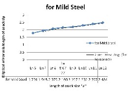
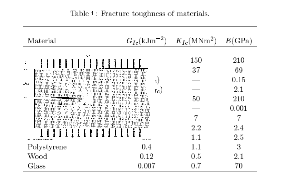
According to Table 1 of fracture toughness of materials, we have found the value of “a” as shown in fig.1 for mild steel as:


Fig.2: Indicating catastrophic increase in crack size for Mild Steel after 24 hours.
A crack of 7 mm is permissible according to technical survey in
24 hours, which needs to be replaced, and crack length expands logarithmically.
The following crack size elliptical depth for a as 7 mm and width of 1.94 mm is acceptable for a time period of 24 hours, for safe side operating condition of roll without damaging the sheets which are passing in between, and a limit of 8.6777 mm and width of 2.16 mm is acceptable for extreme limit, after that there will be flaws in the manufactured sheets, as size of crack “a” increase catastrophically.
And the following roll is to be replaced after the ex- treme limit. So life prediction of roll of mild steel is 24 hours.
Case 2: for Aluminum Alloy


According to Table 1 of fracture toughness of mate- rials, we have found the value of “a” as shown in fig.1 for Aluminum Alloy as:
• Working formula:


IJSER © 2011 http://www.ijser.org
International Journal of Scientific & Engineering Research Volume 2, Issue 7, July-2011 3
ISSN 2229-5518

Fig.3: Indicating catastrophic increase in crack size for Aluminum Alloy after 24 hours.
The value of “a” is within the desired range of 7 mm
and hence the material will bear load for more than 24 hours. The crack tip for Al alloy for loading condition of 20 tones for
24 hours is 4.75210 mm and the corresponding elliptical crack
length is 1.55 mm which is much below the extreme limit of datum crack level at 7 mm and 1.94 mm so the roll made up of aluminum alloy will last long much after 24 hours.
As the critical size of “a” is1.9459 mm. so, the crack
size of the same size will come after 3.25 hours.
i.e. a saving in material and of roll.
The roll will last for 0.1354 days extra. i.e. 321 rolls will last for 365 days. Benefit of 44 rolls per year.
i.e. 4184.1 X 44 = 1,84,118 kg
Approx saving: 1,84,118 X 35 Rs. Saving: Rs. 64,44,130.00
Approximately 64 lakh per year.
*The material Al alloy is very costly about 10 times costlier than iron, so irrespective of its ability to bear load for more than 24 hours, it cannot be used because of its material cost.
Case 3: for Steel Alloy 1


According to Table 1 of fracture toughness of mate- rials, we have found the value of “a” as shown in fig.1 for Steel Alloy 1 as:
24 hours.
The value of “a” is within the desired range of fracture so the following roll of steel alloy 1 with composition (Cr: 0.3%, Ni:
0.025%, C: 0.1%, Si: 1%) will last for more than 24 hours.
As the crack size “a” is 4.9835 mm and hence correspondingly, the crack minor dia is 1.6061 mm.
And the critical crack size is a= 1.9459mm in 24 hours.
So, the critical “a” comes after 2.1 hours, i.e. there is a saving in material.
The roll will last for 0.0875 days extra. I roll work for 1.0875 days.
i.e. 335.632 rolls in 365 days.
i.e. a saving of 29.36 rolls per year
Approx. saving = 29.36 X4184.5
Kg.= 1,22,892.56 Kg saving. Saving: 1,22,892.56 X 35 Rs. Saving of Rs. 43,01,239.713.00
Approximately 43 lakhs per year.
*As the material is having the same composition with slight variation in some composition elements hence the material cost is same to that of cast iron but a saving in roll of 29.36.
4 COMPARATIVE CHART OF LIFE PREDIC- TION
According to the cases observed we have made a
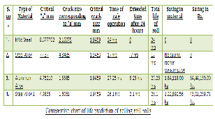
comparative chart for life prediction and total saving per year of roll in terms of material and cost.
Table2: Comparative Chart of Life Prediction of Roll.
5 MATHEMATICAL MODEL CREATION
Mathematical model of the following roll is made on software, the following model is created to find the hard point through which crack will propagate and suitable measure should be employed for its non propagation and some design changes if employed make the stress intensity to distribute and make the roll feasible for longer time.
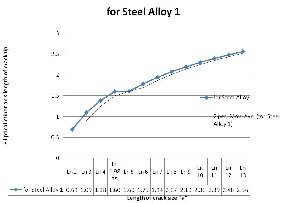
Fig.4: Indicating catastrophic increase in crack size for Steel Alloy 1 after
IJSER © 2011 http://www.ijser.org
International Journal of Scientific & Engineering Research Volume 2, Issue 7, July-2011 4
ISSN 2229-5518
Hence, a mathematical model is created by taking feasible material into consideration, forces, rpm, and other as- pects and make a model which is dimensionally accurate to the actual roll.
The following fig.7 shows that roll will fail from the point mark in red, so the design of roll is to be changed by fiving filleting according to calculation.
Specification:
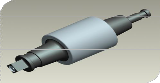
Fig.5 Mathematical model of Roll. [5]
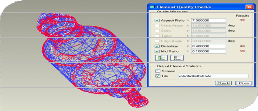
Fig.8 Red points showing stress intensity distribution maximum on peri- phery of original roll.
• Material of Roll is Mild Steel. ST1020.
• Having weight of 4128.69 Kg.
• Surface is Hardened and Grinding is done to make it smooth.
• Required to reduce the thickness of HR( Hot Rolled)
sheets from 4.75 mm to 0.2 mm.
• Force on the surface of roller is 1.7023 X 107 inch pound/ sq. sec. which is 20 tones.
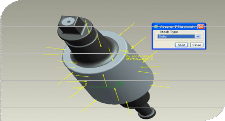
Fig. 6 Mathematical Model of Roll with Forces and other properties in
Dynamic Module Analysis.
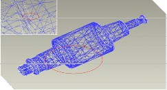
Fig.7 The maximum value of stress on roller surface is shown by the node. (Node ID: 95).
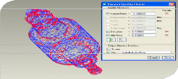
Fig.9 The distribution of red points are less indicating less stress distribu- tion in redesigned roll.
6 RESULT
• Life of rolling mill rollers for different materials have been
found for operating condition of 20 tons of load, 1000 rpm speed and temperature of 2000c.
• The most optimum material is selected for rolling mills accord- ing to cost and life of operation without failure.
• The material selected is ST1020 which is Steel Alloy 1
• The life of Steel Alloy 1 material is 2.1 hours more as com-
pared to mild steel with saving of approx. 43 lakhs per year.
• A total of 9887 elements and 2496 nodes were created.
• Mathematical model is then redesigned according to stresses induced and a redesigned model is created with filleting for less stress concentration on circumference.
• The maximum value of stress on roller surface is shown by the red node. (Node ID: 95). The following max. stress point is reduced in redesigned model.
• Analysis is done on mill roller for stress intensity factor and the final roll mathematical model is accompanied with less stress distribution.
7 CONCLUSION
• The use of a fracture mechanics approach for materials
selection and acceptance can provide a quantitative and more
reliable approach [6].
• At the fabrication stage, such an approach can provide a
quantitative assessment of the advantages to be gained from the use of different steels, different weld consumables.
• The use of fracture mechanics for investigation of steel-
works plant failures can assist in the quantification of likely operating conditions and help in focusing subsequent investiga- tive effort in the appropriate areas.
IJSER © 2011 http://www.ijser.org
International Journal of Scientific & Engineering Research Volume 2, Issue 7, July-2011 5
ISSN 2229-5518
• The use of LEFM based fracture and fatigue analysis for rolling mills can assist in the achievement of maximum life by providing a more accurate assessment of remnant life than con- ventional safety factors methods.
• Result obtained by analytical analysis and by simulation in
PRO-E has been compared and has been seen that the values are very close. It has been seen that the value of optimized length obtained by simulation is 14.400 IN instead of 16.00 inch. The material saving is about 8%.
• During simulation of the roll component using PRO-E software for different abnormal condition it is seen that the stress on the component is well within the limit even when the load is increased much above the normal loading which shows that the considered roll can withstand under abnormal condi- tion.
• During the analysis the worst scenario is obtained for the
unrestrained set in which the node point with maximum stress is on ID: 95.
• Roll component has been analyzed for various normal and abnormal conditions. This analysis is very useful when the
breakdown occurs on its surface due to cracks. But it is not
possible for the expert’s to reach the site within the time, and the machine cannot be started before the maintenance work is completed. So this analysis data library will help to predict the failure and therefore the maintenance of machine can be done by guiding the fellow workers while sitting in the office itself. Thus the breakdown time can be reduced and consequently the cost of maintenance will be reduced.
ACKNOWLEDGEMENT
I express my gratitude to Dr. Ashesh Tiwari sir for guiding me and the faculty members for encouraging me. I also express my sincere thanks to Dr. Tokekar sir for guiding me.
8 REFERENCES
[1] Stress analysis and optimization of rolling mill housing
Using CAE, puneet katyal
[2] Finite element analysis of strip and rolling mills Jian-guo CAO, Jie ZHANG, Ning KONG and Kai-fu MI1School of Mechanical Engnieering, University of Science and Technology Beijing, P.R.China
[3] The application of a fracture mechanics approach to the assessment of steelworks plant, by A.C. Banister
[4] Introduction to fracture Mechanics by C.H. Wang DSTO-
GD-010, Commonwealth of Australia 1996 AR No. AR-
009-786 July 1996
[5] National Steel and Agro Industries Limited (NSAIL) Ghatabillaud, Dist. Dhar.
[6] Tutorials for Pro/ Engineer Wildfire 2.0 by Dr. Zuomin
Dong
[7] I.L.Lim, I.W.Jhonston and S.K.Choi. (1993). Application of singular quadratic distorted isoparametric elements in
linear fracture mechanics. International journal for nu- merical methods in engineering , Vol.36, 247302499.
[8] Nicolas Moes, John Dolbow and Ted Belystschko.
(1999). A finite element method for crack growth wi- thiout remeshing. International journal for numerical
methods in engineering , 1310150.
IJSER © 2011 http://www.ijser.org