
International Journal of Scientific & Engineering Research, Volume 5, Issue 5, May-2014 1505
ISSN 2229-5518
Theoretical Analysis and Performance
Comparison of Different Alternative Refrigerants to HCFC-22
B.HADYA 1, Dr. P. USHA SRI 2
—————————— ——————————
1 INTRODUCTION
N the last seven decades, the CFCs and HCFCs have been used in the field of refrigeration and air condition- ing due to their favourable characteristics. As the signifi- cance of air conditioning for human comfort was consid- ered as a luxury a few decades ago, but now in modern life it has become a necessary for every human being and for commercial purpose. The use of refrigerant has got more significance and HCFCs -22 is one of the important refrigerants in air conditioning all over the world [1]. The major disadvantage of R22 is ozone layer depletion and global warming effect, which causes lot of ill health and diseases for living and non living things. As per the agreement of Montreal and Kyoto protocol 1987 all CFC’S and HCFC’S must be phased out both in developed and developing countries. As per ASHRAE standard -34 all HCFC should be phased out by 2030 [2, 3].The Govt. of India, The Ministry of Environment and Forest (MoEF), emphasizing and giving indications on Environmental
Impact Assessment (EIA).
2 LITERATURE STUDY
To search for alternative to refrigerant( HCFCs group) 22 A comprehensive literature study has been carried out for retrofit to existing vapour compression
————————————————
• 1 Assistant Professor, Mechanical Engineering Depart- ment, U.C.E., Osmania University, Hyderabad, A.P-
500007; hadya.ou@gmail.com
• 2 Professor, Mechanical Engineering Department, U.C.E.,
Osmania University, Hyderabad, A.P-
refrigeration system for various alternate refrigerants for both empirical and simulated results are studied [4], the basic performance and environmental parameters are Ozone layer: Molina and Rowlands (1974) has been ex-
panded into a comprehensive and very complex theory
emphasis about 200 reactions that CFCs are significantly destroyed by UV radiation in the stratosphere. In the year
1987 Hoffman predicted 3 ٪ global ozone depletion with contact of CFCs emissions of 700 thousand tone /year [4-
5].
programme conference held in Montreal in September
1987 the decision taken to phase out ozone depleting sub- stances (ODS) within a fixed time period is known as Montreal Protocol. Some of the feature of MP is as fal- lows. Developed countries will phase out CFCs by
1996.Developing countries will phase out CFCs by 2010
with freeze in 1999 and gradual reduction thereafter. De- veloped countries will phase out HCFCs by 2030 while developing countries have been provided a grace period of ten years i.e. phase out by 2040. Global warming is an- other serious issue. Some naturally occurring substances mainly cause this but CFCs have very large global warm- ing potential. [6- 8].
3 GLOBAL WARMING
IJSER © 2014 http://www.ijser.org
International Journal of Scientific & Engineering Research, Volume 5, Issue 5, May-2014 1506
ISSN 2229-5518
1996 | 100 |
2004 | 65 |
2010 | 35 |
2015 | 10 |
2020 | 5 |
2030 | 0 |
From the table 1, the phase-out of HCFCs uses a cap or limit, based on ozone depletion (ODP) unit con- cept. The base of the cap is determined via the fol- lowing formula: 1989 CFC production X ODP X
From the literature study, in selecting a refrig- erant for a particular purpose its characteristic must be considered and the selection must be made on the basis of its compatibility with the system. [7,8].The desirable properties like Thermodynamic properties,
Physical properties and Chemical Properties re- quires for high COP and safe to use while between different pressures
The simple Vapour Compression Refrigeration cycle is shown in Fig.3. It consists of following four essential parts 1.Compressor, 2.Condenser, 3.Expansion Valve, and
4.Evaporator.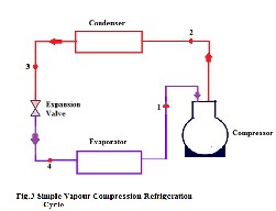
Compressor compresses the vapour refrigerant to the condenser with high pressure and temperature , in the condenser condensation takes place by rejecting heat with cooling medium either water or air as a cooling me- dium the phase transfer takes place from vapour refriger- ant to liquid refrigerant and enters into the Expansion Valve , the function of the expansion valve is to reduce the pressure from high condenser pressure to low evapo- rator pressure by throttling process, finally the liquid re- frigerant enters in the Evaporator where cooling effect is produced by absorbing heat from the cooling space and only pure vapour enters into the compressor
The P-h diagram (Moeller diagram) shown in fig.4 is frequently used in the analysis of Vapour Compression Refrigeration cycle, the significant performance character- istics are Compressor work (Wc), Refrigeration Effect (QE ) and Coefficient of Performance (COP).Process 1 to 2 is compression, 2 to 3 Condensation (Heat Rejection), 3 to
4 Expansion process (Throttling) and 4 to 1 Evaporation
process (Heat absorption), the system performance is cal-
culated as follows
COP = (1) Wc = mr (h 2 - h1 ) (2)
QE = mr (h 4 - h1 ) (3)
IJSER © 2014 http://www.ijser.org
International Journal of Scientific & Engineering Research, Volume 5, Issue 5, May-2014 1507
ISSN 2229-5518
Pressure ratio (Pr) = (4)
Power Required = kW (5)
Where,
h1 and h 2 are Enthalpies of Refrigerant at the inlet
and outlet of compressor (kJ/kg).
h3 = h4 are Enthalpies of Refrigerant at the inlet and
outlet of expansion valve (kJ.
The evaporator pressure (PE ) should be positive and
as near atmospheric as possible. If it is too low, it would
result in large volume of the suction vapour. If it is too high, there exit overall high pressure in the system, which results for stronger equipment and higher cost.
Table 2 shows the theoretical comparison of refriger- ant and their properties like molecular weight, chemical formula, Normal boiling point, Critical Temperature and Critical Pressures. R32 the critical temperature is very low, if the refrigeration cycle is operated near the critical temperature COP reduces, hence the refrigeration critical temperatures should be large.
Table 3 shows the performance parameters for se-
lected refrigerants, In the Reversed Rankine Cycle the evaporator temperature is assumed to enter at -15°C (saturated vapour) and Condenser temperature is as- sumed as 30°C and 40°C, And their performance is compared.
Refrigerant | HCFC- R22 | HFC-R32 | HC- R290(Propa ne) | HC- R600a(Isob utene) |
Molecular weight | 86.48 | 52.042 | 44.1 | 58.13 |
Chemical for- mula | CHClF 2 | CH 2 F 2 | C3 H 8 | (CH 3 )3 CH |
NBP°C | -40.9 | -51.71 | -42.07 | -11.73 |
Critical Temp.°C | 96 | 78.41 | 96.8 | 135 |
Critical pres- sure(bar) | 49.74 | 58.3 | 42.54 | 36.45 |
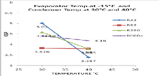
Fig.5.Variation of COP with ambient temperature
IJSER © 2014 http://www.ijser.org
International Journal of Scientific & Engineering Research, Volume 5, Issue 5, May-2014 1508
ISSN 2229-5518
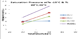
Fig .6. Variation of Pressure Ratio with ambient Tem- perature
From fig.5 to fig.7 shows the performance characteristics for different operating pressures and temperatures, as shown in fig.5 for the ambient conditions if the condenser tempera- ture at 40°C COP for R600a is very high, where as R290 and R32 COP is closely matches, compare to HCFC22 all selected refrigerants gives better COP. Fig.6 shows the pressure ratio i.e saturation of evaporator at -15°C and condenser Pressure at
30°C and 40°C, R600a pressure ratio is high for higher pres- sure ratio the system cost will increase. From fig.7 Power con- sumption for R32 very high and R290 and R600a consumes nearly same power per TR.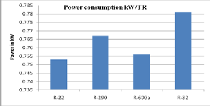
Fig.7 Power consumption for different refriger- ants
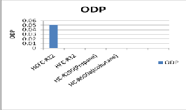
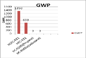
R600a and R290 give better coefficient of Performance with low power consumption, R32 Consumes high power with compare to other refrigerants because, at higher am- bient temperatures the pressure ratio is more. The ad- vantage of R32 is very low flammability with compare to (HCs) R600a and R290. Hydrocarbons refrigerants have ze- ro ODP and very small GWP. As they have Potential of bet- ter performance, they are being used in many countries now days. The only limitation with Hydrocarbon refriger- ants is they are flammable; hence the safety issues must be
addressed in terms of Manufacturing, handling, storage and servicing. The HFCs are transitional compounds sub- stitutes with low ODP, but, these will also have to be re- places. The hydrogen atom causes hydrolysis and also hav- ing GWP, hence these are also uncertain candidates in near future .To prevent the environmental damage and to re- duce the harmful effects the refrigeration industry must shift towards the natural refrigerants.
1. This research work has been carried out under O.U/D.S.T- PURSE Programme, Scheme no A-38, Department of mechanical engineering, University College of Engi- neering, Osmania University.
2. The experiment is studied and conducted At Tecumseh
products India Pvt.Ltd., Balanagar, Hyderabad.
[1]S.Devotta, A.S.Padalkar ansN.K.Sane, “Experimental Performance Analysis of a Retrofitted Window Air Conditioner with R-407C”International Refrigeration and air conditioning confrrence.Paper 533.
[2]ASHRAE, Thermo physical Properties of Refrigerants
Chapter 20, ASHRAE Fundamentals.
[3] HVAC Handbook-2007 Indian Society of Heating Re-
frigerating and Air – Conditioning Engineers, Part I-
Air Conditioning.
tive Analysis of Performance of three Ozone- Friends HFC Refrigerants in a Vapour Compression Refrigera- tor ”, Journal of Sustainable Energy &Environment 2 (2011) 61-64.
[5] PhD. Theses of Dr. Azizuddin on Alternate Refrigerants
for Air Conditioning.
[6]Bukola Olalekan Bolaji,”Effect of Sub-Cooling on the
Performance of R12 Alternatives in Domestic Refrig-
eration system, Thammasat Int.J.Sc.Tech., Vol.15 Jan- March 2010.
[7] Refrigeration and Air Conditioning Book by R.C. ARO- RA.
[8] Refrigeration and Air Conditioning Book by C.P ARORA.and DOMKUNDWER.
IJSER © 2014 http://www.ijser.org