International Journal of Scientific & Engineering Research, Volume 6, Issue 5, May-2015 82
ISSN 2229-5518
The surface roughness effect of transverse patterns on the performance of short bearing
P. I. Andharia, Mital Patel
Abstract— An attempt has been made to investigate the performance of short bearing under the presence of magnetic fluid as a lubricant. Bearing surfaces are considered to be transversally rough. The roughness of the bearing surfaces is characterized by a stochastic random variable with non-zero mean, variance and skew-ness. The modified Reynold’s equation is solved with suitable boundary conditions to obtain the pressure distribution which is then used to calculate the load carrying capacity. Simpson’s 1/3 rule is used for numerical integration. The results are presented graphically as well as in tabular form. It is seen that due to magnetization the performance of bearing system gets improvement. It is also observed that the roughness causes the system adversely. The investigation suggests that the negative effect of roughness can be reduced by positive effect of magnetization parameter. W hile designing the bearing system, the roughness must be given due to consideration.
Index Terms— Load carrying capacity, Magnetic fluid, Reynold’s equation, Short bearing, Transverse roughness
—————————— ——————————
The slider bearing is the simplest and frequently encountered among the hydrodynamic bearings. In slider bearing, the film is non-diverging and continuous. Such bearings are designed to support the axial loads. Exact solutions of Reynold’s equa- tion for slider bearing with various simple film geometries are described in several books and research papers (Lord Rayleigh [1], Archibald [2]). Prakash and Vij [3] analysed the hydrody- namic lubrication of a plane inclined slider bearing taking var- ious geometries into consideration and shown that the quality of being porous decreased the friction and load carrying ca- pacity. Patel and Gupta [4] extended the above analysis of Prakash and Vij [3] by incorporating slide velocity. They proved that in order to increase the performance of the bear- ing system the value of the slide parameter deserved to be minimized.
However, bearing surfaces could be roughened
through manufacturing process, the wear and the spontaneous
damage. In order to interpretation for the effect of surface
roughness Christensen [5, 6] developed a stochastic concept
and introduced an averaging film model to lubricated surfaces with striated roughness. Number of investigators has imple- mented a stochastic method to model the random roughness (Tzeng and Seibel [7], Christensen and Tonder [8-10]). Chris- tensen and Tonder [8-10] presented all inclusive general anal- ysis for surface roughness based on a general probability den- sity function by modifying and developing the method of Tzeng and Seibel [7]. Consequently many investigators have been carried out to study the effect of surface roughness, such
as the works in the hydrodynamic journal bearing by Taranga et.al. [11], the hydrodynamic slider bearings by Christensen and Tonder [12] and the squeeze film spherical bearing by Andharia et al. [13]. In all these studies conventional lubricant were used. The use of magnetic fluid as a lubricant modifying the performance of the bearing has splendidly recognized. Agrawal [14] considered the configuration of Prakash and Vij [3] in the presence of a magnetic fluid lubricant and establish its performance better than the one with conventional lubri- cant. Bhat and Deheri [15] extended the analysis of Agrawal [14] by studying a magnetic fluid based porous composite slider bearing. Bhat and Deheri [16] discussed a general po- rous slider bearing with squeeze film formed by a magnetic fluid. Recently Patel and Deheri [17] presented behavior of transversely rough magnetic fluid based porous short bearing. Also Andharia et al. [18] has discussed performance of a mag- netic fluid based longitudinally rough short bearing.
Here it has been proposed to study and analyse the
performance of transversely rough short bearing in the pres-
ence of a magnetic fluid lubricant considering asymmetric roughness with non-zero mean.
The geometry and configuration of bearing is shown in Fig. 1, which is infinite in Z-direction.
• P.I. Andharia
————————————————
.
Dept. of Mathematics, M. K. Bhavnagar University, Bhavnagar.
Gujarat, India.
E-mail: pareshandharia@yahoo.com
• Mital Patel (Ph.D. student)
Dept. of Mathematics, M. K. Bhavnagar University, Bhavnagar. Gujarat, India.
E-mail: mital.kachhadia6611@gmail.com [Fig. 1]
IJSER © 2015 http://www.ijser.org
International Journal of Scientific & Engineering Research, Volume 6, Issue 5, May-2015 83
ISSN 2229-5518
The slider moves with the uniform velocity U in X- direction. The length of bearing L and breadth B is in Z- direction, where B<<L. The pressure gradient Əp/Əz is very larger than pressure gradient Əp/Əx. The maximum and min- imum film thicknesses are h1 and h2 respectively. The as- sumptions of usual hydrodynamic lubrication theory are tak- en into consideration in the development of the analysis.
The bearing surfaces are assumed to be transversely
rough. The thickness h of the lubricant film is given by![]()
h = ![]() + (1) Where is the mean film thickness and
+ (1) Where is the mean film thickness and ![]() is the deviation from the mean film thickness characterizing the random roughness of the bearing surfaces.
is the deviation from the mean film thickness characterizing the random roughness of the bearing surfaces. ![]() is considered to be sto- chastic in nature and governed by probability density function
is considered to be sto- chastic in nature and governed by probability density function![]()
, where ![]() is the maximum deviation from the mean film thickness.
is the maximum deviation from the mean film thickness.
The mean α, the standard deviation σ and the meas- ure of symmetry ![]() the random variable
the random variable ![]() are defined by the relationship :
are defined by the relationship :![]()
α = E ( ) (2) σ2 = E [( – α)2] (3) ![]() = E [( – α)3] (4)
= E [( – α)3] (4)
Where E is the expectancy operator defined by![]()
E(R) = ![]() (5) Wherein (Tzeng and Saibel [7])
(5) Wherein (Tzeng and Saibel [7])
permeability and ![]() is the lubricant viscosity. The associated boundary conditions are
is the lubricant viscosity. The associated boundary conditions are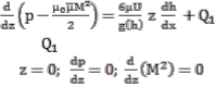
![]() and
and ![]() (10) By integrating Eq. (8) with respect to z
(10) By integrating Eq. (8) with respect to z
(11)
Where is a constant.
At and ![]() = 0
= 0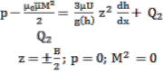
Again by integrating Eq. (10) with respect to z
(12)
Where is a constant.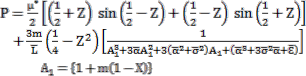
At and ![]() By Eq. (11) and introducing the dimensionless quantities
By Eq. (11) and introducing the dimensionless quantities 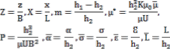 (13) The pressure distribution in dimension form
(14) Where![]()
The load carrying capacity of bearing
= 0, elsewhere (6)
It is easily observed that α, σ and ![]() are independent of x
are independent of x
The magnetic field is oblique to the stator as in
Agrawal [14]. Following discussions carried out by Prajapati
[19] regarding the effect of various forms of magnitude of
magnetic field is expressed as
![]() (7) Where B is the breadth of bearing and K is a suitably chosen constant from dimensionless point of view (Bhat and Deheri [16]).
(7) Where B is the breadth of bearing and K is a suitably chosen constant from dimensionless point of view (Bhat and Deheri [16]).
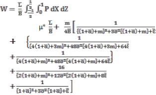
Dimensionless load carrying capacity is obtained as
= 0.15853
256
(15) (16)
The lubricant film is considered to be isoviscous and incompressible and the flow is laminar.
With the usual assumption of hydrodynamic lubrication, the modified Reynold’s equation for film pressure is given by
(17)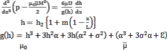
![]() (8) Applying averaging process, the modified Reynold’s equation for film pressure (Prajapati [19], Bhat [20], Deheri, Andharia and Patel [21]) is given by
(8) Applying averaging process, the modified Reynold’s equation for film pressure (Prajapati [19], Bhat [20], Deheri, Andharia and Patel [21]) is given by
(9) Where
while is the magnetic susceptibility, is the free space
It is seen that Eq. (14) represents the expression for the dimen- sionless pressure distribution and Eq. (17) determined the load carrying capacity in dimensionless form. These performance characteristics depend on various parameters such as magnet- ization parameter µ*, length ratio L/h2, breadth ratio B/h2, aspect ratio m, roughness parameters σ, α and Ԑ etc. Eq. (17) is numerically integrated using Simpson’s 1/3 rule for different values of µ*, σ, α and Ԑ. The results are presented graphically in Figs. (2) – (9) and also numerically in table form as Table (1)
– (13).
IJSER © 2015 http://www.ijser.org
International Journal of Scientific & Engineering Research, Volume 6, Issue 5, May-2015 84
ISSN 2229-5518
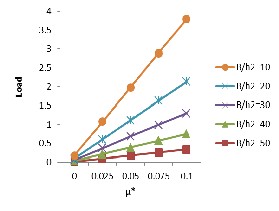
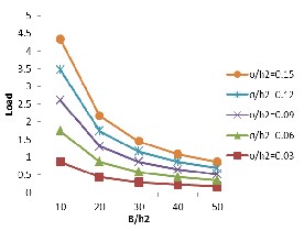
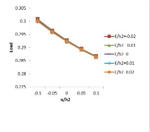
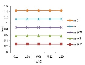
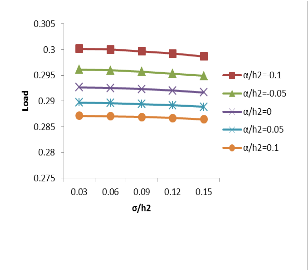
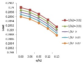
Figs. (2) and (3) represent the variation of load carry- ing capacity with respect to magnetization parameter µ* for various values of L/h2 and B/h2 respectively. These figures show that the load carrying capacity increases significantly due to magnetic fluid lubricant. Fig. (4) shows the effect of L/h2 on dimensionless load carrying capacity for various val- ues of B/h2 and load carrying capacity increases considerably due to L/h2. Fig. (5) suggests the effect of B/h2 on dimen- sionless load carrying capacity for various values of σ/h2. From this figure it is clear that the load carrying capacity de- creases sharply due to B/h2. Fig. (6) – (8) present the profile of the load carrying capacity with respect to σ/h2 for various values of m, α/h2 and Ԑ/h2. These figures suggest that the effect of standard deviation is almost negligible so far as the dimensionless load carrying capacity is concerned. Fig. (9)
shows the variation of load carrying capacity with respect to α/h2 and Ԑ/h2. From the figure it is clearly shown that load carrying capacity decreases marginally due to α/h2.
Tables 1 – 4 show the effect of µ* on the dimensionless load carrying capacity for various values of aspect ratio m, σ/h2, α/h2 and Ԑ/h2 respectively. From these tables it is clear that the load carrying capacity increases sharply due to mag- netization and the effect of aspect ratio m, σ/h2, α/h2 and Ԑ/h2 is negligible with respect to magnetization parameter µ*. Tables 5 – 8 present the effect of L/h2 on the dimensionless load carrying capacity for various values of aspect ratio m, σ/h2, α/h2 and Ԑ/h2 respectively. It is noticed that the dimen- sionless load carrying capacity increases significantly due to L/h2. Table 9 – 11 suggest the variation of load carrying ca- pacity with respect to B/h2 and aspect ratio m, α/h2 and Ԑ/h2 respectively. It is shown that the effect of aspect ratio m, α/h2 and Ԑ/h2 on load carrying capacity decreases with increasing values of B/h2. Table 12 and 13 represent the effect of α/h2 and Ԑ/h2 on the dimensionless load carrying capacity for var- ious values of m. Furthermore, the aspect ratio has a strong positive effect in the sense that the load capacity increases sharply.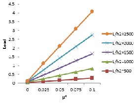
and L/h2.
and B/h2.

L/h2 and B/h2.
B/h2 and σ/h2.
IJSER © 2015 http://www.ijser.org
International Journal of Scientific & Engineering Research, Volume 6, Issue 5, May-2015 85
ISSN 2229-5518
σ/h2 and m.
α/h2 and Ԑ/h2.
Table 1
Variation of load carrying capacity with respect to µ* and m
m | Load | ||||
m | µ* = 0 | µ* = 0.025 | µ* = 0.05 | µ* = 0.075 | µ* = 0.1 |
0.25 | 0.014383 | 0.146492 | 0.278600 | 0.410708 | 0.542817 |
0.50 | 0.021405 | 0.153513 | 0.285621 | 0.417730 | 0.549838 |
0.75 | 0.024949 | 0.157057 | 0.289165 | 0.421274 | 0.553382 |
1.00 | 0.026662 | 0.158770 | 0.290879 | 0.422987 | 0.555095 |
2.00 | 0.026528 | 0.158636 | 0.290744 | 0.422853 | 0.554961 |
Table 2
Variation of load carrying capacity with respect to µ* and σ/h2
σ/h2 | Load | ||||
σ/h2 | µ* = 0 | µ* = 0.025 | µ* = 0.05 | µ* = 0.075 | µ* = 0.1 |
0.03 | 0.025479 | 0.157588 | 0.289696 | 0.421804 | 0.553913 |
0.06 | 0.025371 | 0.157480 | 0.289588 | 0.421696 | 0.553805 |
0.09 | 0.025193 | 0.157302 | 0.289410 | 0.421518 | 0.553627 |
0.12 | 0.024949 | 0.157057 | 0.289165 | 0.421274 | 0.553382 |
0.15 | 0.024642 | 0.156750 | 0.288858 | 0.420967 | 0.553075 |
σ/h2 and α/h2.
Table 3
Variation of load carrying capacity with respect to µ* and α/h2
σ/h2 and Ԑ/h2.
Table 4
Variation of load carrying capacity with respect to µ* and Ԑ/h2
Ɛ/h2 | Load | ||||
Ɛ/h2 | µ* = 0 | µ* = 0.025 | µ* = 0.05 | µ* = 0.075 | µ* = 0.1 |
-0.02 | 0.025243 | 0.157351 | 0.289459 | 0.421568 | 0.553676 |
-0.01 | 0.025144 | 0.157252 | 0.289361 | 0.421469 | 0.553577 |
0.00 | 0.025046 | 0.157154 | 0.289263 | 0.421371 | 0.553479 |
0.01 | 0.024949 | 0.157057 | 0.289165 | 0.421274 | 0.553382 |
0.02 | 0.024853 | 0.156961 | 0.289069 | 0.421178 | 0.553286 |
Table 5
Variation of load carrying capacity with respect to L/h2 and m
IJSER © 2015 http://www.ijser.org
International Journal of Scientific & Engineering Research, Volume 6, Issue 5, May-2015 86
ISSN 2229-5518
Table 6
Variation of load carrying capacity with respect to L/h2 and σ/h2
Table 13
Variation of load carrying capacity with respect to Ԑ/h2 and m
σ/h2 | Load | ||||
σ/h2 | L/h2 = 500 | L/h2 = 1000 | L/h2 = 1500 | L/h2 = 2000 | L/h2 = 2500 |
0.03 | 0.157588 | 0.289696 | 0.421804 | 0.553913 | 0.686021 |
0.06 | 0.157480 | 0.289588 | 0.424696 | 0.553805 | 0.685913 |
0.09 | 0.157302 | 0.289410 | 0.421518 | 0.553627 | 0.685735 |
0.12 | 0.157057 | 0.289165 | 0.421274 | 0.553382 | 0.685490 |
0.15 | 0.156750 | 0.288858 | 0.420967 | 0.553075 | 0.685183 |
Table 7
Variation of load carrying capacity with respect to L/h2 and α/h2
Table 8
Variation of load carrying capacity with respect to L/h2 and Ԑ/h2
Table 9
Variation of load carrying capacity with respect to B/h2 and m
Table 10
Variation of load carrying capacity with respect to B/h2 and α/h2
Table 11
Variation of load carrying capacity with respect to B/h2 and Ԑ/h2
Table 12
Variation of load carrying capacity with respect to α/h2 and m
This investigation suggests that the effect of roughness pa- rameters is negligible. This conditional effect increases with the larger values of σ/h2, α/h2 and Ԑ/h2. The results show that the negative effect of B/h2, σ/h2, α/h2 and Ԑ/h2 can be reduced to a larger extent by the positive effect of magnetiza- tion parameter µ* and L/h2, choosing a suitable values of as- pect ratio m.
[1] Lord Rayleigh, “Notes on the Theory of Lubrication”, Philosophical
Magazino and Journal of Science, Vol. 53, pp. 1-12, 1918.
[2] F.R. Archibald, “Load Capacity and Time Relation for Squeeze
Films”, Jour. Basic Engg. Trans., ASME. Sear, Vol. D78, pp. 231-245,
1956.
[3] J. Prakash and S.K. Vij, “Hydrodynamic Lubrication of Porous Slid- er”, J. Mech. Engg. Sci. Vol. 15, pp. 232-234, 1973.
[4] K.C. Patel and J.L. Gupta, “Hydrodynamic Lubrication of a Porous
Slider Bearing with Slip Velocity”, WEAR, Vol. 85, pp. 309-317, 1983. [5] H. Christensen, “Stochastic Model for Hydrodynamic Lubrication of
Rough Surfaces”, Proceedings of the Institutes of Mechanical Engineers, Vol. 184, pp. 1013-1025, 1969-70.
[6] H. Christensen and K.C. Tonder, “Some Aspects of the Functional
Influence of Rough Surfaces in Lubrication”, WEAR, Vol. 17, pp. 149-
162, 1971.
[7] S.T. Tzeng, E. Saibel, “Surface Roughness Effect on Slider Bearing
Lubrication”, Trans. ASLE, Vol. 10, pp. 334-340, 1967.
[8] H. Christensen and K.C. Tonder, “Tribology of Rough Surfaces: Sto- chastic Models of Hydrodynamic Lubrication”, SINTEF Report No.
10/69-18, 1969a.
[9] H. Christensen and K.C. Tonder, “Tribology of Rough Surfaces: Par- ametric Study and Comparison of Lubrication Models”, SINTEF Re- port No. 22/69-18, 1969b.
[10] H. Christensen and K.C. Tonder, “The Hydrodynamic Lubrication of Rough Bearing Surfaces of Finite Width”, ASME-ASLE lubrication conference; Paper no. 70-lub-7, 1970.
[11] R. Taranga, A.S. Sekhar, B.C. Manjumdar, “The Effect of Roughness Parameter on the Performance of Hydrodynamic Journal Bearing With Rough Effects”, Tribology Int., Vol. 32, pp. 231-236, 1999.
[12] H. Christensen and K.C. Tonder, “The Hydrodynamic Lubrication of Rough Bearing Surfaces of Finite Width”, ASME Journal of lubrication Technology, Vol. 93, pp. 324-330, 1971.
[13] P.I. Andharia, G.M. Deheri, and J.L. Gupta, “Effect of Longitudinal Surface Roughness on the Behaviour of Squeeze Film in a Spherical Bearing”, International Journal of Applied Mechanics and Engineering, Vol. 6, pp. 885-897, 2001.
[14] V.K. Agrawal, “Magnetic Fluid Bases Porous Inclined Slider Bear-
ing”, WEAR, Vol. 107, pp. 133-139, 1986.
IJSER © 2015 http://www.ijser.org
International Journal of Scientific & Engineering Research, Volume 6, Issue 5, May-2015 87
ISSN 2229-5518
[15] M.V. Bhat and G.M. Deheri, “Porous Composite Slider Bearing Lu- bricated with Magnetic Fluid”, Japanese Journal of Applied Physics, Vol.
30, pp. 2513-2514, 1991.
[16] M.V. Bhat and G.M. Deheri, “Porous Slider Bearing with Squeeze Film Formed by a Magnetic Fluid”, Pure and Applied mathematika sci- ences, Vol. 39(1-2), pp. 39-43, 1995.
[17] Jimit R. Patel and Gunamani Deheri, “Behavior of a Magnetic Fluid
Based Rough Short Bearing”, i-Scholar, Vol. 1, No. 1, pp. 29-48, 2013. [18] P.I. Andharia, G.M. Deheri, S. Mehta, “Performance of a Magnetic
Fluid- based Longitudinally Rough Short Bearing”, Proceedings of In- ternational Conference on Advances in Tribology and Engineering Systems, Springer India, 2014. (Conference proceedings)
[19] B.L. Prajapati, “On Certain Theoretical Studies in Hydrodynamic and Electro-magneto Hydrodynamic Lubrication”, Ph.D. thesis, S.P. Uni- versity, Vallabh Vidyanagar, 1995.
[20] M.V. Bhat, “Lubrication with a Magnetic Fluid”, Team Spirit (India) Pvt., Ltd, 2003.
[21] G.M. Deheri, P.I. Andharia and R.M. Patel, “Transversely Rough Slider Bearing with Squeeze Film Formed by a Magnetic Fluid”, In- ternational Journal of Applied Mechanics and Engineering, Vol. 10.1, pp.
53-76, 2005.
IJSER © 2015 http://www.ijser.org