International Journal of Scientific & Engineering Research Volume 4, Issue3, March-2013 1
ISSN 2229-5518
Study of Effectiveness of Courbon’s Theory in the
Analysis of T-beam Bridges
M.G. Kalyanshetti and R.P. Shriram
Abstract-In order to compute the bending moment due to live load in a girder and slab bridge, the distribution of the live loads among the longitudinal girders has to be determined. There are many methods to estimate load distribution. In this project Courbon’s method is used to estimate the load distribution as it very popular and widely used because of its simplicity. But the Load factor obtained by Courbon’s method is constant for all spans and this indicates the effect of variation of span is not at all considered. Therefore it is proposed to study “effectiveness of Courbon’s theory” for various spans of bridge by varying number of longitudinal girders. In this project STAAD software is used in which bridge models are analyzed using grillage method. Finally load factor obtained from grillage analogy are compared with the Courbon’s load factors to find out the difference and to obtain a new equation which considers the effect of span. The detailed study is carried out for four lane and six Lane bridges of spans 15m, 20m, 35m, 30m, 35m using IRC class A loading by varing a number of longitudinal girders. Also the study reveals that Courbon’s theory gives higher values of bending moments for exterior girder. Therefore the problem of over estimation of load on exterior girder is solved by using Modified Courbon’s equation.
Keywords- Longitudinal girder, Courbon’s theory, Grillage analogy, T-beam bridge, Staad-pro, Indian Road Congress, IRC Live Loads.
When a concentrated load is applied over a single beam within the width of an open spaced beam and slab deck, some load sharing clearly takes place with adjacent beams, but the member directly under the load obviously deflects more than the others and the slab which provides the transverse connectivity between beams is therefore deformed. A bridge deck is basically a platform between piers and abutments. It could be a slab or a slab and grid of longitudinal and transverse beams. For designing the platform elements it is essential to analyze their response to
the applied load and estimate how much of this load is
5) Section-V : Steel road bridges
6) Section-VI : Composite construction
7) Section-VII : Foundations and Substructures
8) Section-VIII : Bearings
This is one of the earliest forms of rational analysis of bridge decks and is very popular in view of its simplicity. The expression for reaction factor for individual longitudinal girders (share of the total load by the individual longitudinal girders) according to this method is
given by following equation-
apportioned to each one of them. For this project IRC class
A loading is used and load factors are calculated by using
Pi =
![]()
n 1 +
![]()
n.e.di
∑ d2
Courbon’s theory. Finally these load factors are compared to the load factors obtained from Grillage analogy and correction factor is found out. New modified Courbon’s equation is developed by using this correction factor which solves the problem of overestimation of exterior girder.
The Indian Road Congress (IRC) has formulated standard specifications and codes of practice for road bridges with a view to establish a common procedure for the design and construction of road bridges in India. The specifications are collectively known as the Bridge code. Prior to the formation of the IRC bridge code, there was no uniform code for the whole country. Each state (or province) had its own rules about the standard loading and stresses.
The Indian Roads Congress (IRC) Bridge code as available
now consists of eight sections as below:
1) Section-I : General features of design
2) Section-II : Loads and stresses
3) Section-III : Cement concrete (Plain and reinforced)
4) Section-IV : Brick, stone and block masonry
Where,
P = total live load
e = eccentricity of the live load (or c.g.of loads in case of multiple loads),
di = distance of girder i from the axis of the bridge, n = number of longitudinal girders
The method consists of ‘converting’ the bridge deck structure into a network of rigidly connected beams at discrete nodes i.e. idealizing the bridge by an equivalent grillage. The deformations at the two ends of a beam element are related to the bending and torsional moments through their bending and torsional stiffness’s.
When a bridge deck is analysed by the method of Grillage Analogy, there are essentially five steps to be followed for obtaining design responses:
i. Idealization of physical deck into equivalent grillage
ii. Evaluation of equivalent elastic inertias of members of grillage
iii. Application and transfer of loads to various nodes of
grillage
IJSER © 2013 http://www.ijser.org
International Journal of Scientific & Engineering Research Volume 4, Issue3, March-2013 2
ISSN 2229-5518
iv. Determination of force responses and design envelopes and
v. Interpretation of results.
Analysis of T-beam bridge deck is done by Courbon’s theory and Grillage Analogy with the help of STAAD software.
A complete schedule of parametric study is given in following table.
Table 1: List of studied parameters
Type of Bridge | T-Beam Bridge | |
Span | 15,20,25,30,35m | |
Lane of Bridge | Four lane | Six lane |
Carriageway width | 14m | 21m |
No. of longitudinal girders | 3,4,5,6 | 5,6,7 |
Thickness of longitudinal girders | 500mm | 500mm |
No. of cross girders | 5 | 5 |
Thickness of cross girders | 250mm | 250mm |
Depth of deck slab | 215mm | 215mm |
Thickness of wearing coat | 75mm | 75mm |
IRC standard live load | Class A-4 trains | Class A- 6 trains |
Parametric study is carried out as per following cases: Table 2: list of cases of parametric study
All bridge models prepared by grillage analogy are analyzed using STAAD. Live load Bending moments of all the spans are determined by Grillage method and by Courbon’s theory. Also load factors by grillage analogy and by Courbon’s method are calculated.
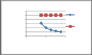
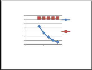
Comparison of load factor by Grillage Analogy and
Courbon’s method is carried for each case and presented in the form of graph as follows-
Variation of load factor of exterior girder (Girder A) w.r.t span for four Lane Bridge with 3 longitudinal girders
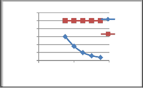
Variation of load factor of exterior girder (Girder A) w.r.t span for four Lane Bridge with 4 longitudinal girders
Variation of load factor of exterior girder (Girder
A) w.r.t span for four Lane Bridge with 5 longitudinal girders
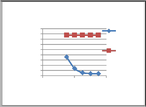
Variation of load factor of exterior girder (Girder
A) w.r.t span for four Lane Bridge with 6 longitudinal girders
Variation of load factor of exterior girder (Girder A) w.r.t. span for six Lane Bridge with 5 longitudinal girders
Variation of load factor of exterior girder (Girder A) w.r.t. span for six Lane Bridge with 6 longitudinal girders
Variation of load factor of exterior girder (Girder A) w.r.t. span for six Lane Bridge with 7 longitudinal girders
Load factor
3.1
3
2.9
2.8
2.7
2.6
2.5
0 20 40
Span in 'm'
Grillage method
Courbon' s theory
IJSER © 2013 http://www.ijser.org
International Journal of Scientific & Engineering Research Volume 4, Issue3, March-2013 3
ISSN 2229-5518
w.r.t span for four Lane Bridge with 3 longitudinal girders
w.r.t span for four Lane Bridge with 6 longitudinal girders
Load
2.35
2.3
2.25
Grillage method
Load
2.7
2.65
2.6
2.55
2.5
Grillage method
Courbon
factor
2.2
2.15
2.1
2.05
2
1.95
0 20 40
Span in 'm'
Courbon's theory
factor 2.45
2.4
2.35
2.3
2.25
0 20 40
Span in 'm'
's theory
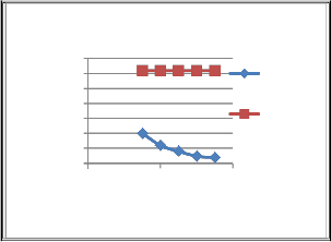
w.r.t span for four Lane Bridge with 4 longitudinal girders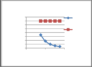
w.r.t. span six Lane Bridge with 5 longitudinal girders
1.9
1.85
1.8
Grillage method
Load
2.25
2.2
2.15
2.1
Grillage method
Load 1.75
factor 1.7
1.65
1.6
1.55
0 20 40
Span in 'm'
Courbon's theory
factor2.05
2
1.95
1.9
0 20 40
Span in 'm'
Courbon's
theory
w.r.t span for four Lane Bridge with 5 longitudinal girders
w.r.t. span six Lane Bridge with 6 longitudinal girders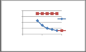
1.95
1.9
Grillage
1.6
1.5
Load 1.4
factor 1.3
1.2
0 20 40
Span in 'm'
Grillage method
Courbon's theory
Load facto1.85
1.8
1.75
1.7
1.65
0 20 40
Span in 'm'
method Courbon' s theory
w.r.t. span six Lane Bridge with 7 longitudinal girders
IJSER © 2013 http://www.ijser.org
International Journal of Scientific & Engineering Research Volume 4, Issue3, March-2013 4
ISSN 2229-5518
Following observations are obtained from the detailed parametric study
1. For exterior girders bending moment obtained by
Courbon’s theory is more than the bending
not considered but using Grillage anology it is observed that load factor is not constant for all the spans and it is decreasing from lower span to higher span. Also Courbon’s theory gives higher values of bending moments for exterior girder. To overcome this problem and to obtain actual bending moment a second degree equation is developed by using parabolic function which gives the correction factor
to get actual load factor for each span. Finally Courbon’s equation is modified by using correction factor which is
given as below
moment obtained by Grillage method for all the spans and for interior girder bending moment
Pi =
![]()
P
n 1 +
![]()
n. e. di
∑ d
× Correction factor
obtained by Courbon’s theory is less than the
bending moment obtained by Grillage method for all the spans.
2. Variation of load factor in Girder A by Courbon’s theory is constant for all the spans and variation of load factor in Girder A by Grillage method is varying from 15m span to 35m span. It is observed that this variation is in decreasing order.
Therefore there is need to correct the equation of load factor
given by Courbon’s theory as the load factor obtained by Courbon’s theory is constant for all spans. Hence correction factors for each span are calculated and the equation of correction factor for Girder A is obtained. For this the maximum value of correction factor is selected for each span and a single graph is provided which will be applicable to all the cases of four lane and six lane. Finally the equation is obtained by using a parabolic function y = a
+ bx + cx2. For this the method of least squares is used.
Following equation is obtained by using method of least squares-
y = 0.000134x2 - 0.0098x + 1.056
Here, x = Span of the bridge, y = Correction factor
By considering correction factor, Courbon’s equation for
Load factor is modified as
Where, correction factor for each span is calculated by
using the equation
y = 0.000134x2 - 0.0098x + 1.056
The above Modified Courbon’s equation gives the values of load factor which are nearly same as obtained by grillage analogy. Therefore the problem of over estimation of load on exterior girder is solved by using Modified Courbon’s equation.
1. D. Johnson Victor, “Essentials of Bridge Engineering”- Oxford & IBH Publishing Company Pvt, Ltd. New Delhi.
2. N. Rajagopalan ‘Bridge Superstructure’- Narosa
Publications.
3. Surana C.S., Agrawal R. (1998), “Grillage Analogy in Bridge Deck Analysis”, Tata McGraw Hill.
4. T.R. Jagdish & M.A. Jairam, Design of bridge
structures, Pentice hall of India private Limited, New Delhi.
5. IRC:5-1998-Standard Specifications and Code of
Practice for Road Bridges, Section I – General
Features of Design (Seventh Revision)
6. B. C. Punmia Ashok Kumar Jain ‘Comprehensive
RCC Designs’ - Lakshmi Publications.![]()
P
Pi = n 1 +
![]()
n. e. di Correction factor
i
![]()
M. G. Kalyanshetti- Assistant Professor, Civil
Finally by using this modified Courbon’s equation load factors are corrected.
This study is carried out for four lane and six Lane bridges of spans 15m, 20m, 35m, 30m, 35m using IRC class A loading by varing a number of longitudinal girders.
From the observations, it can conclude that-
Load factor obtained by Courbon’s method is constant for all spans and this indicates the effect of variation of span is
Engineering Department, Walchand Institute of Technology Solapur, India.PH-9422646598. Email: mgkalyanshetti@rediffmail.com
R.P. Shriram- PG student ME Civil Structures,
Walchand Institute of Technology Solapur, India.PH-8149878760. Email:rasikashriram@gmail.com
IJSER © 2013 http://www.ijser.org