International Journal of Scientific & Engineering Research Volume 4, Issue3, March-2013 1
ISSN 2229-5518
Study of Developed Cuk Converter for
Renewable Energy Sources
Parastoo Khademi Astaneh, Khalil Valipoor
Abstract— Fuel cells are one of today’s fastest growing renewable energy technologies that have a great promise for distributed generation and electric vehicle application because of their high efficiency, low environmental impact and scalability. This paper compares developed topologies of Dc–Dc cuk converters for renewable energy sources, like fuel cell. The studied topologies have the advantages of clear conversion processes, high efficiency and high output voltage with a small ripple. Also these topologies have simple structure, and fewer switches compare to a simple cuk converter and other classic Dc-Dc converters used in renewable energy applications. To be precise and real, we use Fuel cell stack and simulate this with Matlab simulink.
Index Terms— DC-DC converter, Renewable energy sources, Fuel cell stack, Cuk Converter.
—————————— ——————————
1. INTRODUCTION
Due to economic problems and depletion of world fossil fuel supplies, renewable energy development for power
generation received many attentions. Fuel cells are one of the alternative energy resources that have recently attracted a great deal of attention. Fuel cell is a device that converts the chemical energy of a fuel directly to electrical energy. Fuel cell has higher energy storage capability and is a clean energy source [1-5].
Fuel cells can serve as an emergency energy source during long-term power outages; also they can be used as a portable power system. The fuel cells are used in every aspect because of their advantages: clean and efficient way of supplying electric power [6-8]. For example they are used in the standalone purposes at homes, hospitals, industries and now are use in numerous vehicles.
However, fuel cells have a slow response due to their slow internal electromechanical and thermodynamic response [1,2]. To optimize the fuel cell system performance, a fuel cell DC-DC converter with an appropriate controller which can regulate the power flow and automatically adjust the converter output voltage is needed.
The Dc-Dc converter should have high efficiency and
Cuk converter is a combined type of converter which is using both circuits of boost and buck converter and will change the voltage to a lower or to higher level of voltage based on the characteristics that are designed for it. It can also reverse the voltage waveform and act as a step-down and step-up voltage source. Reversing the voltage is only in capability of this type of converter and this makes it special.
Voltage-lift (VL) technique is an effective method that could be applied in electronic circuit design.
In this paper we use a developed high efficient Dc-Dc cuk converter based on voltage lift type converters and analysis the simulation results in matlab simulink. Using this method avoids using transformers and cascade connection and lead to a simple structure.
In designing the converter for fuel cell, we consider the fuel cell innate characteristics instead of considering it only as an ideal DC voltage source. We use a 10 volt fuel cell in our simulation.
————————————————
Parastoo Khademi Astaneh is currently pursuing PHD degree program in power electronic engineering in Mohaghegh University of Ardebil, Iran,
E-mail: P.khademi@uma.ac.ir.
Dr Khalil Valipoor is currently a Faculty Member Of power engineering department of Mohaghegh University of Ardebil, Iran, E-mail: khvalipoor@gmail.com
minimum ripple.
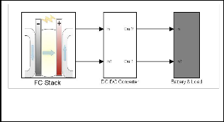
Figure 1. Block diagram of a fuel cell system used for portable applications.
IJSER © 2013 http://www.ijser.org
International Journal of Scientific & Engineering Research Volume 4, Issue3, March-2013 2
ISSN 2229-5518
converters can perform positive to negative dc – dc voltage increasing conversion with higher voltage transfer gains.
The circuit diagram is shown in figure 2 and the equivalent circuits during switching-on and switching-off are shown in
figure 3.
2 ANALYSIS OF DEVELOPED DC-DC CUK CONVERTER
2.1 DC-DC INTERFACE
Currently, no standard output voltage rating for fuel cells has been established. Most of the present fuel cell stack modules produce an output voltage in the range 24–150 VDC. Hence, due to nonideal characteristics of fuell cell the
development and designing of power conditioning units play
an important role to interface the fuel cell system with standalone/grid connected systems. This interface should:
Control the fuel cell voltage
Convert the fu el cell output to the appropriate type and magnitude
Deliver a hig h power factor (grid applications)
Provide little to no har monics
Operate efficiently under all conditions and
Add little to the cost of the overall system.
The power electronics interface for fuel cells often utilise DC–DC converters and inverters to modify the fuel cell voltage and convert the DC voltage to AC. In this section we
use a new topology for the DC-DC interface.
2.2 The Developed Converter
The Selection of power conditioning unit is based on some significant factors like lower cost, higher efficiency, and electrical isolation, ripple free and reliable operation. The efficiency of the power conditioner unit depends upon the conduction and switching losses. The conduction losses can be effectively reduced by reducing the usage of components and their operating ranges. The switching losses can be reduced by soft switching technics
In order to reduce the cost and to increase their reliability
the selection of topology must have reduced component count.
The voltage-lift (VL) technique is an effective method that could be applied in electronic circuit design. A negative output dc–dc converter (Voltage-lift-type Cuk converters) applying series Cuk implementing VL techniques is studied as the interface of a fuell cell system.
The developed Cuk Dc-Dc converter is based on voltage lift type
Cuk converters is a suitable choise for fuel cell interface [9]. We

Figure 2. Developed Cuk converter
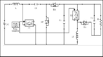
Figure3. Developed Cuk converter equivalent, a) during Switch on, b)
during switch off.
The switches S and S1 are switched simultaneously. When S and S1 turn on, D1 is on, Df and Do are off. When S and S1 turn off, D1 is off, Df and Do are on. Capacitor C1 performs its characteristics to lift the output capacitor voltage VCo by the capacitor voltage VCs.
As shown in figure 3, when the switches are on, the capacitores C1 and Cs are parallel. Since Cs and C1 are sufficiently large, we have:
1
show that compared with the Cuk converter prototype, this

VC1 VC 2 Vin
1 D
(1)
IJSER © 2013 http://www.ijser.org
International Journal of Scientific & Engineering Research Volume 4, Issue3, March-2013 3
ISSN 2229-5518
The inductor current iL1 increases when the switch is on and decreases when the switch is off. The corresponding voltages
across L are VCs and -(VCo -VC1).
Therefore with the sec-voltage balance principle, we can obtain the relationship between the input and output voltages
The circuit are under the simulation condition that Vin=10V, R =100 Ω ,L =1mH, L1 =500µH, Cs =110µF, C1=22µF, Co=4µF
and f 100 kHz.
VO

1 V (1 D)2 in
(2)
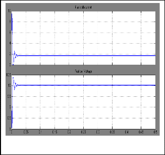
The output characteristics of the fuel cell stack was shown in figure 4 and figure5. The fuel cell provides a 10 volt Dc voltage
In this converter the peak-to-peak voltage variation of vo ,
∆vo is equal to (IoDT /Co ). Therefore the variation ratio of vo can be calculated from equation 3. It indicates that the output voltage variation ratios are determined by the interactions caus ed by D, R, f and Co. So increasing the capacitance of out- put capacitor can effectively improve the output ripper.

v0
with a small ripple. This simulation is performed in CCM
mode.
In this simulation with the input voltage Vin=10v that we obtain from the fuel cell, the duty cycle is 50% and Vo=40 volt.
2
V0
D

2RCo f
3. Simulation Results
The simulink model of a fuel cell system with the proposed

DC-DC converter was shown in figure 6.
Stack voltage vs current
25 (52,24.23)
20
(100,20)
15
10
5
0 10 20 30 40 50 60 70 80 90 100
Current(A)
Stack power vs current
Fig. 5. Output voltage and current waveforms of Fuel cell Stack.
2 (2kW)
1.5
1
0.5
0
(1.26kW)
0 10 20 30 40 50 60 70 80 90 100
Current(A)
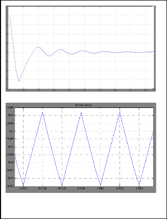
The simulation results show that using this developed converter can increase the efficiency and decrease the output ripple. We obtain that the output voltage variation ratios ®s is equal to 5.3e-4. Therefore the near-zero ripple is achieved with
this topology.
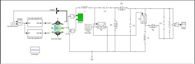
Fig. 4. Fuel cell Stack characteristics.
International Journal of Scientific & Engineering Research Volume 4, Issue3, March-2013 4
ISSN 2229-5518
increasing duty cycle due to the parasitic elements. This problem solved in the new structure. In addition to these advantages, the circuit structure is simple and can be used in practical implementations.
CONCLUSIONS
A simulation analysis of using a developed DC-DC cuk converter for fuel cell systems is studied. Simulation results show that this topology has high efficiency with high output voltage and a small ripple compare to classic cuk converters and can be a suitable choice to use as the DC-DC converter in fuel cell renewable systems. Since the studied converters avoid using transformers and cascade connection, the relative simple structures are beneficial to potential practical applications in
future.
Figure7. Output voltage of the DC-DC developed Converter
References
[1] Ahmad Saudi Samosir, Tole Sutikno, Abdul Halim Mohd Yatim, “Dynamic Evolution Control for Fuel Cell DC-DC Converter”, TELKOMNIKA, Vol.9, No.1, April 2011, pp, 183-190.
[2] Dwari S, Parsa L, “A Novel High Efficiency High Power Interleaved Coupled-Inductor Boost DC-DC Converter for Hybrid and Fuel Cell Electric Vehicle”, Vehicle Power and Propulsion Conference. 2007, Vol.1, pp, 399-404.
[3] Xu H, Wen X, Qiao E, Guo X, Kong L, “ High Power Interleaved Boost Converter in Fuel Cell Hybrid Electric Vehicle”, IEEE International Conference on Electric Machines and Drives. 2005; Vol.1, pp,1814-1819.
[4] Samosir AS, Yatim AHM, “Dynamic evolution control of bidirectional DC- DC converter for interfacing ultracapacitor energy storage to Fuel Cell Electric Vehicle system”, Power Engineering Conference. Australia.
2008; 1:1-6.
[5] Samosir AS, Yatim AHM. “Implementation of Dynamic Evolution Control of Bidirectional DC-DC Converter for Interfacing Ultracapacitor Energy Storage to Fuel Cell System” IEEE Transactions on Industrial Electronics. 2010; 57(10): 3468-3473.
[6] Thounthong P, Rael S, Davat B, “Control Strategy of Fuel Cell and Supercapacitors Association for a Distributed Generation System. Transactions on Industrial Electronics”, 2007; (12): 3225–3233.
[7] Nehrir M H, Wang C, Shaw S R, “Fuel cells: promising devices for distributed generation”, IEEE Power Energy Magazine. 2006; 4(1): 47–53
[8] Samosir A S, Anwari M, Yatim A H M, “A simple PEM Fuel Cell Emulator using Electrical Circuit model”, International Power and Energy Conference. Singapore. 2010; 1: 881–885.
[9] M. Zhu F.L. Luo, “Voltage-lift-type Cuk converters: topologyand analysis”, IET Power Electron. , 2009 , Vol. 2, Iss. 2, pp. 178 – 191.
Figure8. Output voltage of the classic DC-DC cuk Converter.
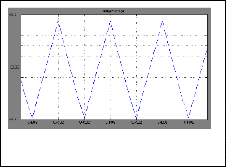
Also we should attain that in a classic cuk converter, to obtain a 40 volt Dc output, the duty cycle must be 80%, and
this is not a good condition. Because there are a limiton
IJSER © 2013 http://www.ijser.org
International Journal of Scientific & Engineering Research Volume 4, Issue3, March-2013 5
ISSN 2229-5518
IJSER lb)2013
http://www.ijserorq