to bus-j (or from bus-j to bus-i).
International Journal of Scientific & Engineering Research Volume 2, Issue 9, September-2011 1
ISSN 2229-5518
Static Available Transfer Capability determination in deregulated Power market using AC distribution factors
Devendra Kumar Tiwari, Laxmi Srivastava and Shishir Dixit
are used to check whether any of the lines flow (MW) limits and bus voltage magnitude (Volt) limits are not violated. The solution algorithm is tested on
IEEE 6- Bus system and IEEE 30-Bus system to assess the ATC.
—————————— ——————————
As we know that whole world is undergoing through restructur
ing process for better utilization of resources and to make use of managerial efficiencies into all the three facets of the power sys- tem. Open access and neutrality the important features of deregu- lation. With the open access, electric are utilities try to maximize the utilization of existing transmission network and thereby over stressing some of the transmission corridors of power systems and endangering the security and reliability of the power system. In transferring the bulk amount of power over integrated network poses the limitations due to systems binding limits. These are thermal limits, bus voltage magnitude limit, voltage stability and dynamic stability limits and generators reactive power limits [6], [7].
The maximum amount of power that can be transferred over the existing amountis called available transfer capability. To operate the power system securely and reliably and at the same time to gain the profit of bulk power transfers, the transfer capability must be calculated and the power system should be planned and operated such that power transfers do not exceed the transfer capability. The ATC concept is as follows: from a base condition, as the load increases along the fixed direction, the generation also increases accordingly along in that direction considering contin- gencies. When system limiting factor is reached, the generation above the base case is known as available transfer capability [1],[2].The ATC concept is similar to North American Electric Re- liability Council’s (NERC’s) incremental transfer capability *1+,*2+. ATC is the minimum transfer under first line outage condition, known as First Contingency Incremental Transfer Capability (FCITC). Accurate measurement of ATC on major portion of the interface of the power system gives an important indication of power system security and reliability. In case of bilateral transac- tions, It can be used as an important indicator to the capability of a system to transport or deliver energy over and above already subscribed transmission uses. Any bilateral/multilateral transac- tion can only be committed when there is sufficient available
transfer capability in the transmission network. ATC assessment helps in optimal location of new independent power producers (IPP) and transmission congestion management [9].
Many research papers published for Available Transfer Capability (ATC) determination but in a few of them discussed accurate and fast ATC determination in view of lines MW flow limit considera- tion and voltage limits (Generators MVAR limits) consideration to maximize secured and reliable transmission utilization [6-10]. In reference [4], ATC is estimated based on continuation power flow (CPF) and repeated power flow though provides very accurate ATC results as it considers system non-linearity and control changes but limitations of not suitable for large power system, cannot be applied on real time applications due to computational complexity and slow computation. Reference [3] proposes an op- timization-based method in which optimization problem is for- mulated with equality and inequality constraints of power flow. But solution of optimization problem for large power system be- comes very time consuming therefore not suitable for real time application.Linear sensitivity factors [5],[ 12], and [13] uses DC Power Transfer Distribution Factors (DC-PTDFs) and Line Outage Power Transfer Distribution Factors (LO-PTDFs) derived from DC load flow. DC-PTDFs are easy to calculate and giving fast compu- tations. But less accurate as in DC power flow voltage and reac- tive power effects are not considered. AC Power Transfer Distri- bution Factors (AC-PTDFs) are also proposed for ATC determina- tion [7-10]. AC-PTDFs are derived around base operating point using full AC Load Flow analysis. In AC-PTDF based methods, reactive power limits and voltage limits are also considered and therefore more accurate with less computation complexity.
ATC determination based on AC Power transfer distribution fac- tors (AC PTDFs) and Voltage Distribution Factors (VDFs) are derived from Jacobian matrix of base operating point of AC load
IJSER © 2011
International Journal of Scientific & Engineering Research Volume 2, Issue 9, September-2011 2
ISSN 2229-5518
flow results which is s a simple and non-iterative approach to bilateral and multilateral transactions and gives fast and more accurate results.
2.1 AC Power Transfer Distribution Factors
AC Power Transfer Distribution Factors (ACPTDFs) are defined as the fractional changes in transmission lines flow due to any transacted power in between any source and sink pairs. Consider a bilateral wheeling transaction![]() between a seller (source) bus- m and a buyer (sink) bus -n. Further consider a line carrying a part of transacted power and let it be connected between bus-i and bus-j. For a change in real power transaction between the above seller and buyer buses above the base operating point by
between a seller (source) bus- m and a buyer (sink) bus -n. Further consider a line carrying a part of transacted power and let it be connected between bus-i and bus-j. For a change in real power transaction between the above seller and buyer buses above the base operating point by![]() , if change in transmission line quantity i.e. change in lines real pow- er flow is
, if change in transmission line quantity i.e. change in lines real pow- er flow is![]() , then AC Power transfer distribution factor [7]
, then AC Power transfer distribution factor [7]![]() =
=![]() (1) Transmission quantity is taken as the real power flow from bus-i
(1) Transmission quantity is taken as the real power flow from bus-i
to bus-j (or from bus-j to bus-i).
2.2 Voltage Distribution Factors
Voltage distribution factors (VDFs) are defined as the change in the bus voltage magnitude ![]() at any bus-i due to the change in any transaction i.e.
at any bus-i due to the change in any transaction i.e.![]() between seller bus-m and buyer bus-n. Let the base case voltage magnitude at any bus-i is
between seller bus-m and buyer bus-n. Let the base case voltage magnitude at any bus-i is ![]() and after change due to a transaction
and after change due to a transaction![]() is
is![]() . The Voltage distribution factors
. The Voltage distribution factors
![]() (2) Where,
(2) Where, ![]()
Available Transfer Capability from a bus/ zone m to another bus/ zone n can be determined considering both, the lines flow limit and bus voltage limits is as follows.
ATC at base case, between bus/ zone m and bus/ zone n using lines flow limit criterion is calculated using ACPTDFs [7- 10].![]()
![]()
![]()
![]() (3) Where,
(3) Where,![]() is the maximum real power flow (MW) limit of line connected between bus-i and bus-j ;
is the maximum real power flow (MW) limit of line connected between bus-i and bus-j ;![]() is the real power flow in line connected between bus-i and bus-j under base case operating condition ;
is the real power flow in line connected between bus-i and bus-j under base case operating condition ; ![]() is the AC Power Transfer Distribution Fac- tors for line connected between bus-i and bus-j when transaction is taking place between a seller bus-m and a buyer bus-n ;
is the AC Power Transfer Distribution Fac- tors for line connected between bus-i and bus-j when transaction is taking place between a seller bus-m and a buyer bus-n ;
. is the total number of lines.
ATC at base case considering bus voltage limit violation
(minimum limit only) criterion has been calculated using VDFs![]() (4) Where,
(4) Where, ![]() is voltage magnitude at bus-i under base case operat-
is voltage magnitude at bus-i under base case operat-
ing condition; ![]() is the minimum voltage magnitude limit at bus-i (voltage regulation is ± 4 % and the lower bus voltage limit
is the minimum voltage magnitude limit at bus-i (voltage regulation is ± 4 % and the lower bus voltage limit![]()
0.96 p.u.is considered in the present analysis); is the vol- tage distribution factor of bus-i when transaction is taking place between a seller bus-m and a buyer bus-n ; is the total number of buses.
Run a base case load flow to find all the transmission quantities.
Form the full Jacobian ![]() to include all
to include all
the buses except the slack bus and find its inverse which is known as the sensitivity matrix![]() .
.
Consider a bilateral transaction![]() .
.
Identify the sending bus-m and receiving bus-n.
Assume some +ve injection at seller bus-m (changes in real power ![]() and -ve injection -
and -ve injection - ![]() at a buyer bus-n and form the mismatch vector.
at a buyer bus-n and form the mismatch vector.
Compute the change in voltage angles and its magnitudes, update the voltage profile.
Compute the new values of transmission
quantities or line power flows change in real power flows for all the lines from its base case condition.
Compute the new values of bus voltage magnitudes and change in bus voltage magnitudes from its base case condition for all the buses.
Compute the AC power transfer distribu-
tion factors for all the lines and voltage distribution fac- tors for all the buses.
Repeat above steps except step one for each bilateral transaction.
Compute ATC values by ACPTDF method
for all lines and select the minimum and declare it as ATC (MW) value considering the lines flow limit consid- eration.
Compute ATC value using VDFs method for all the buses and select the minimum and declare the ATC (MW) considering the bus voltage limit criteria.
To establish the effectiveness of the sensitivity factors based ap- proach for ATC calculation, studies conducted on two test sys-
IJSER © 2011
International Journal of Scientific & Engineering Research Volume 2, Issue 9, September-2011 3
ISSN 2229-5518
tems IEEE 6-bus System and IEEE 30-bus system.
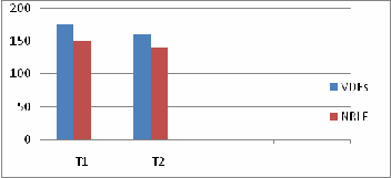
The generator bus data, load bus data and line data for IEEE 6-bus System are derived from Reference [11, 14].Two bilateral wheeling transactions, T1 (a seller bus-2, a buyer bus-6) and T2 (a seller bus-
3, a buyer bus-5). ATC is determined using ACPTDFs and VDFs
method. Which are presented in Table 1 and Table 2. These ATC
results are also compared with the results obtained by NRLF me-
thod. Their graphical presentation is shown in fig.1 and fig.2 re- spectively.
The line diagram, generator data, load bus data and line data for IEEE 30-bus system are taken from ref. [11, 15]. Four bila- teral non-simultaneous wheeling transactions T1, T2, T3 and T4 are carried out to determine the ATC. T1 (a seller bus-8, a buyer bus-
25), T2 (a seller bus-5, a buyer bus-30), T3 (a seller bus-11, a buyer
bus-26) and T4 transaction in between (a seller bus-2, a buyer bus-
28). ATC is determined using ACPTDFs and VDFs method. Which
are presented in Table 3 and Table 4 respectively. These ATC re- sults are also compared with the ATC obtained by NRLF method. Their graphical presentation is shown in fig.3 and fig.4. Table 5 and Table 6 are for ATC values determined by ACPTDFs and VDFs method when all four bilateral transactions occurrence is simultaneous. ATC results are also determined in same tables using NRLF method. Their graphical presentation is shown in fig.5 and fig.6 respectively.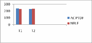
Figure 1 Comparison of ATC values for two bilateral non- simultaneous transactions on IEEE 6-bus System consider- ing line flows limit criteria
Figure 2 Comparison of ATC values by VDFs with NRLF method for two bilateral Non-Simultaneous Transactions on IEEE 6-bus System considering bus voltage limits criteria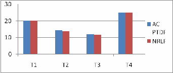
Figure 3 Comparison of ATC values for four bilateral Non Simtaneous Transactions on IEEE 30-bus System (ACPTDF and NRLF)
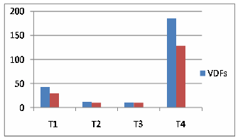
Figure 4 Comparison of ATC values for four bilateral Non- Simultaneous Transactions on IEEE 30-bus System (VDF and NRLF)
IJSER © 2011
International Journal of Scientific & Engineering Research Volume 2, Issue 9, September-2011 4
ISSN 2229-5518
TABLE 1 ATC (MW) VALUES FOR IEEE 6-BUS SYSTEMS COSI- DERING LINES FLOWS (MW) LIMIT CRITERIA FOR TWO BILA- TERAL TRANSACTIONS
Table 4 ATC (MW) IEEE 30-bus system considering bus
Voltage limits (Bilateral Trans.) criteria using VDFs method
Table 2 ATC (MW) IEEE 6-Bus system considering bus
Voltage limits (Bilateral Trans.)
Table 3 ATC (MW) IEEE 30-bus system considering Lines Flows limit (Bilateral Trans.) and using ACPTDFs Method
Transaction | AC PTDF | NRLF | Critical Line |
T1(8 - 25) | 20.309 | 20.4 | 25 – 26 |
T2 (5 – 30) | 14.38 | 13.97 | 27 – 28 |
T3(11 – 26) | 12.17 | 11.70 | 25 – 26 |
T4 (2 – 28) | 25.065 | 25.00 | 6 – 28 |
————————————————
Devendra Kumar Tiwari is ME in Electrical Engineering from MITS,Gwalior and currently Assistant Professor in SITM,Lucknow,
India, Mob-8765080162,d_tiwari4@rediffmail.com.
Laxmi Srivastava is PhD in power system from IIT Roorki and currently Professor and Head of Electrical Engg.Department, MITS, Gwalior (MP).
Shishir Dixit is currently persuing PhD from MNIT, Bhop- al (MP) in Power System and is Professor in Electrical En- gineering, MITS, Gwalior (MP).
Recent blackouts in the United States and many other parts of the world provided a growing evidence that certain actions are ur- gently needed to ensure that the power system always remains secure, permitting maximum power transactions over intercon- nected power system. The Available Transfer Capability has been assessed for various simultaneous and non-simultaneous transac- tions on IEEE 6-bus and IEEE 30-bus System and from the results it has been observed that the ATC calculated by using AC distri- bution factors gives results closer to the results as obtained by repeated Newton-Raphson Load Flow analysis. Since this ap- proach is non-iterative and computationis faster, therefore me- thodology can be applied to on-line applications on the power system. Further, from the results it has been also observed that in some cases of ATC considering lines flow(MW) limit governs over the bus voltage limits, whereas in some cases bus voltage limit dominates over the lines flow (MW) limits.
[1] North American Electric Reliability Council (NERC), Available Transfer Capability definitions and determination, NERC Report, June 1996.
*2+ Transmission Transfer Capability Task Force” Force Transmission Transfer Capability, “North American Reliability Council, Princeton, New Jersey, 1995.
*3+ H.Grevener, C.Nwankpa, “AvailableTransfer Capability ity and First
Order Sensitivity”, IEEE Transaction on Power Systems, Vol. 14, No.2, May 1999, pp. 512-51.
*4+ V. Ajjarappu and C. Christy, “The Continuation Power Flow: A Tool
IJSER © 2011
International Journal of Scientific & Engineering Research Volume 2, Issue 9, September-2011 5
ISSN 2229-5518
For Steady State Voltage Stability Analysis”, IEEE Trans on Power Sys[-15] Hadi Saadat “Power System Analysis,” Tata McGraw-Hill
tems, Vol.7, No.1, pp.416-423, Feb.1992.
[5] G. C. Ejebe, J. Tong, G.G.Waight, J.G. Frame, X. Wang and W. F. Tinney,” Available Transfer Capability Calculations”, IEEE Trans.on Power Systems, Vol.13, No.4, pp 1521-1527, Nov 1998.
*6+ Ashwani Kumar, S. C. Srivastava and S. N. Singh,” AC Power Transfer Distribution Factors for Allocating Power Transactions in a Deregulated Market”, IEEE Power Engineering Review, Vol. 22,
No. 7, pp. 42 – 43, July 2002.
Publising Company Limited edition 2002.
*7+ Ashwani Kumar, S. C. Srivastava and S. N. Singh, “Available Transfer Capability (ATC) determination in a competitive Electricity Market Using AC. Distribution Factors” Electric Power Components and system,Vol. 32, pp. 927-939, 2004.
*8+ P. Venkatesh, R. Gnanadass and Narayan Prasad y, Padhy“Available Transfer Capability (ATC) on determination in a competitive Electricity Market using AC Power transfer Distribution Factors”, IEEE Transaction on Power system Vol. 1, Issue 2, Art. 1009, 2004.
*9+ Y. K. Wu, “A novel algorithm for ATC calculations and applications in Deregulated electricity markets”, IEEE E Publication on Energy Power and Energy Systems, 9, Vol.29, pp. 810-821, 2007.
[10] Kiran Seelam, Surender Kumar Yellagoud, Veeranjaneyulu
Puppala,”An improved evaluation method for available transfer Capabil- ity by Incorporating the reactive power flows”, IEEE Journal on Engi- neering Science and Technology Vol. 2(12), 7572-7578, 2010.
[11] O. Alsac, B. Stott,“Optimal load flow with steady state security”,
IEEE Transaction Power Apparatus System, PAS-93, vol. 3, pp. 745-751, 1974.
[12] G. C. Ejebe, James G.Waight, Manuel Santos-Nieto, and William F.Tinney, “Fast Calculation Linear Available Transfer Capability”, IEEE Transaction on Power Systems, Vol.15, No.3, pp. 1112-1116, Aug 2000.
[13] G.C. Ejebe, J. Tong, J.G. Waight, J.G. Frame, X. Wang and W.F.
Tinney, “Available Transfer Capability Calculations”, IEEE Transactions on Power Systems, Vol. 13, No. 4, November 1998. [14] A. J. Wood and Bruce F Woolen Berg, “Power Generation
Operation and Control”, Second Edition John Wiley & Sons.
IJSER © 2011