International Journal of Scientific & Engineering Research Volume 2, Issue 9, September-2011 1
ISSN 2229-5518
Some Aspects of Performance Improvement of Pelton Wheel Turbine with Reengineered Blade and Auxiliary Attachments
Suraj Yadav
Abstract- Pelton wheel is the only hydraulic turbine of the impulse type in common use, is named after an American engineer Laster A Pelton, who contributed much to its development around the year 1880. Therefore this machine is known as Pelton turbine or Pelton wheel. It is an efficient machine particularly suited to high heads, many modifications is being suggested up to now the major modification was near 1903 after that no major modification is being implemented. The author in this paper with his noble and native concept tried to increase the efficiency of the turbine with the modification in the blade and with some auxiliary attachments which will lead to less wastage of the head and result in better efficiency.
Index Terms— Hydraulic turbine, impulse type, reaction type, camber angle, central bucket design, auxiliary attachments, auxiliary bucket design, gear assembly.
1. INTRODUCTION
—————————— ——————————
elton wheel turbine is one of the famous turbines which are mostly used for the hydro plants. This is of impulse type and is used for high head, although the efficiency of
such turbines are not so comparable with the reaction tur- bines, because most of the energy is wasted, due to the split- ting of water which is not being utilized and get wasted, due to this efficiency of the turbine is not so as the efficiency of other turbines like axial or reaction turbines. Related to the same context many modifications were suggested for the en- hancement of the efficiency but the major change which was adopted or implemented was around 1903 after it there was no further modification were implemented.
So this work is purely intended to enhance the efficiency of the
pelton wheel turbine with the modification in the blade design
and some of the auxiliary attachments which ultimately lead to the enhancement of the efficiency of pelton wheel turbine.
2.0 EXISTING MODULE OF PELTON WHEEL

In pelton wheel there is large circular disc or wheel on which a number of spoon shaped buckets are spaced uniformly round is periphery. The wheel is driven by jets of water being dis- charged at atmospheric pressure from pressure nozzles. The nozzles are mounted so that each directs a jet along a tangent to the circle through the centers of the buckets.
————————————————
Suraj yadav is currently student of mechanical engineering of batch
08-12, at Government Engineering College, Bhavnagar, Gujarat, India. PH: +919033405840.Email: suraj_mech08@yahoo.com.
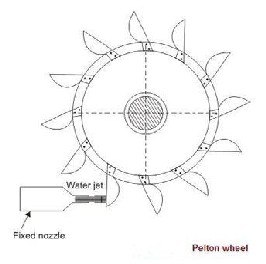
Fig 1,‖ shows the outline of the pelton wheel, down the centre of each bucket, there is a splitter ridge which divides the jet into two equal streams which flow round the smooth inner surface of the bucket and leaves the bucket with a relative ve- locity almost opposite in direction to the original jet. For max- imum change in momentum of the fluid and hence for the maximum driving force on the wheel, the deflection of the water jet should be 180. In practice, however, the deflection is limited to about 165 degree so that the water leaving a bucket may not hit the back of the following bucket. Therefore, the camber angle of the buckets is made as 165 degree. Thus we can’t have the camber angle greater than 165 and up to now no consideration have been taken on the velocity of the out going fluid leaving on the bucket.
Fig 1: outline of pelton wheel.
―
IJSER © 2011
http://www.ijser.org
International Journal of Scientific & Engineering Research Volume 2, Issue 9, September-2011 2
ISSN 2229-5518
2.1 Present Bucket Design:
The bucket consist of central splitter on which the jet strike and get distributed equally to both the side although it has a laminar path then also the distribution is not so distributed to a particular path, which may cause imbalance of little bit, also the water which coming out from the side of blades after working have sufficient amount of energy which get wasted and not being utilized. This all factor leads to the less efficien- cy of the turbine.
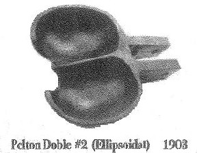
―Fig 2,‖ shows the bucket of the pelton wheel turbine used.
Fig 2: present bucket design. Reference example:
As an example of an actual Pelton wheel, one worked for a
time generating electricity in Southern California with the fol- lowing specifications. Pitch diameter, 162" (2.06 m); operating speed, 250 rpm (26.18 rad/s); head, 2200' (670.6 m). The theo- retical V is √(2gh) = 114.6 m/s, while the peripheral velocity u
= 53.86 m/s. Then, 2u = 108 m/s, very close to V and probably closer to the actual jet velocity. This wheel probably developed about 60,000 hp on a flow of around 7 m3/s. The ratio of the runner velocity u to the ideal jet velocity √(2gh) is usually de- noted φ. For a Pelton wheel working at maximum efficiency, φ is about 0.5. [1]
Thus half of the energy of the fluid jet get wasted thus in this
author have suggested some modification for the same.
3.0 MODIFIED DESIGN
3.1 Modifications
For the better efficiency the author suggested the modification in the bucket design, which earlier just work as the impact bucket will work as half impact as well as half reaction type, also the author has suggested auxiliary attachments in context to use the energy of the outgoing fluid after striking the cen- tral bucket.
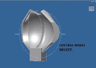
gets spitted after striking the bucket’s central splitter, the path of the central bucket is actually converging in nature, it pro- vide a path whose area decreases a bit towards outside. In this at the exit side of the central bucket there is the splitting of fluid in laminar manner and also it immerge form the exit side with a velocity.
Fig 3: modified central bucket.
―Fig 3,‖ shows the design of the central bucket which will provide a convergent passage for the jet of fluid. Thus there will be fluid flow from the exits side with certain impact.
3.3 The Auxiliary Side Wheel
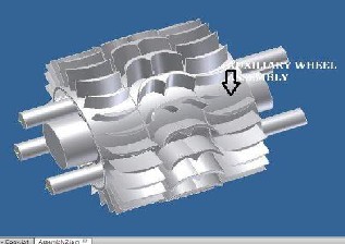
Now to utilize the energy of the fluid coming out of the central wheel the author suggested the auxiliary attachments, two auxiliary wheels on either side central wheel assembly with side buckets mounted on the auxiliary wheel. ―Figure 4,‖ shows an over view of the attachment of the auxiliary wheel assembly.
It consists of set of buckets which are mounted on the wheel. In such a manner that the jet of water which is coming out of the central wheel bucket gets stroked on the side bucket, mak- ing the auxiliary wheel to rotate.
3.2 Modification in Central Bucket Design
It consists of special partial bucket nozzle which provides a
converging passage after splitting form the central splitter. Thus it provides a regular path to the splitting fluid which
Fig 4: overview of the auxiliary wheel arrangement.
IJSER © 2011
http://www.ijser.org
International Journal of Scientific & Engineering Research Volume 2, Issue 9, September-2011 3
ISSN 2229-5518
3.4 Details about the Auxiliary Wheel Bucket
These are actually diverging in nature and it will work both as the impulse and the reaction. ―Fig 5,‖ shows the modified de- sign of the bucket which will be of diverging in nature, thus when the jet from the converging blade of the central bucket strike on these blades, this will provide gradually increasing area thus there will be reduction in the velocity of jet and the pressure will increase and at exit side there will be minimum velocity in the fluid and most of the energy will be utilized.
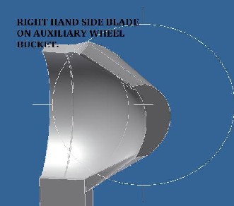
Thus due to this there will be rotation of the auxiliary wheel assembly, which will rotate due to the effect of the jets striking on the buckets of the auxiliary wheel this rotation will be in opposite direction to the central wheel assembly.
Fig 5: Modified design of side bucket (right side).
3.5 Details about the Gear Arrangement
Due to the effect of impact full exit of the jet of fluid after strik- ing the partial nozzle bucket, on the auxiliary side wheel buckets, the wheel rotates this rotation is opposite to the rota- tion of the central wheel assembly. Thus this gear assembly’s help to drive the main shaft in the same direction to the rota- tion of central wheel assembly, this type of gear assembly have sun and planet type of arrangement.
It consists of:
- One internal gear. (On which the auxiliary wheel buckets are
mounted)
- Three intermediate external gear (These gears are fixed and can rotate only on its axis.)
- And one external gear (on the main shaft).
―Figure 6,‖ shows the gear arrangement which help to drive
the main shaft in the same direction.
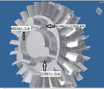
Fig 6: Detail of gear arrangement
3.6 Over-All Modification
Conceptual design overview:
The modifications consist of modified central blade, two aux-
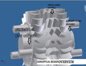
iliary wheel assemblies and spectacular gear assembly.
Fig: 7: conceptual design overview.
―Fig 7,‖ shows the conceptual overall design theme of the modification, and act as aid for the visualization of the concept of modified design.
4.0 CONCLUSION
In this we can take advantage of both the reaction phenomena of reaction turbines and impulse phenomena of the impulse turbine.
IJSER © 2011
http://www.ijser.org
International Journal of Scientific & Engineering Research Volume 2, Issue 9, September-2011 4
ISSN 2229-5518
Also we can use the unutilized energy of the outgoing fluid from the central bucket which will lead to the enhancement of the efficiency.
Also we can implement this over low headed falls for power generation.
5.0 ACKNOWLEDGMENT
I would like to thanks Prof. M.A LOHIA (Associate Professor
& Head) and Asst. Prof. JANAK B. VALAKI. Department of
Mechanical Engineering, Government Engineering College, Bhavnagar, Gujarat. For their valuable guidance and help as and when needed.
6.0 REFERENCES:
[1] International Journal of Engineering & Technology IJET Vol: 9 No: 9 -
241 –
1929091 IJET-IJENS @ International Journals of Engineering and Sciences
IJENS
Analytical Study on Flow through a Pelton Turbine
Bucket Using Boundary Layer Theory
I.U. Atthanayake
Department of Mechanical Engineering
The Open University of Sri Lanka
Nawala, Sri Lanka.
[2] Papers presented at national association of mining history organisa-
tions’ Conference at Aberystwyth, 5-8 July 2002. Volume 15, nose, 4/5,
2004.
THE TENGENTIAL IMPULSE WATER WHEELS IN CALIFORNIA GOLD MINING, Robert A. Kraft and Robert H. same.
[3] Draughty, Hydraulic Turbines, Mc Graw Hill Book Company, 1920, Third Edition
[4] Small & Micro Hydropower, 10/28/2009, Volume 9, Issue 4
www.smallhydro.com
[5]New Technologies for Pelton Turbines, VATECHHYDRO, www.vatech-hydro.com.
[6] A textbook of fluid mechanics and hydraulic machines, by Dr. RK
bansal.
IJSER © 2011
http://www.ijser.org