International Journal of Scientific & Engineering Research, Volume 5, Issue 1, January-2014 150
ISSN 2229-5518
Smartphones and off the shelf hardware for 3D scanning in mobile robots
Hasit Mistry, Sayali Lunkad, Sphoorti Joglekar, Anuj Deshpande
Smart Phones
—————————— ——————————
WITH the advent of 3D printing, scanning 3D objects is generating a lot of interest. To be fair, 3D scx`anning, just like 3D printing, is not entirely a new concept. It has being used in automotive, aerospace, robotics, CAD, architecture, design and prototyping for quite some time now. But as 3D printers are becoming cheaper and more accessible, there is a need to have a consumer friendly 3D scanner. This scanner will have to be portable and easy to operate so as to fit the use case scenario of consumer grade appliances.
A smartphone involves various interfaces for communicating with other similar devices or completely different set of appliances which add even more functionality. Our 3D scanner involves support for connecting to a 3D printer over Bluetooth, WiFi and USB(OTG). This will eliminate the need for a laptop as an intermediate step while 3D printing.
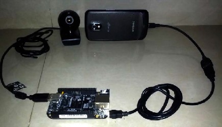
The arrangement consists of a webcam and a mobile phone with image capturing ability , placed horizontally in a straight line with their optical axes parallel to each other. The two cameras with overlapping view fields capture every scene from two different viewpoints having a desired distance from the object.
IJSER © 2014 http://www.ijser.org
International Journal of Scientific & Engineering Research, Volume 5, Issue 1, January-2014 151
ISSN 2229-5518
The depth perception from stereo vision uses the triangulation principle. The principle is basically derived from the mechanism used by our eyes to view objects in the real world. The concept of stereo vision is to capture two or more images from a 3D view such that they provide different angular aspect of the object, from which we can extract details to get a wholesome picture of the object. In this paper we use two cameras separated by a fixed
distance to capture the view. This is known as binocular vision [ 1].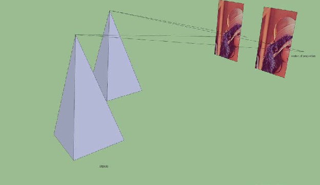
IJSFig 2.2 TriangulaEtion Principle R
The triangulation principle states that the intersection of the line of sight of every pair of matching point from
the surfaces of two captured images determines a point in 3D space. We get the relative position of an object with respect to the stereo camera. Based on this relative position, we can calculate the absolute position of the point in 3D space, since we know the absolute position of the camera and it’s relative position to the point in question.
The main issue in this approach is finding the point which is the intersection of the line of sights of the two cameras. Various types of noise are involved and hence the lines don’t always intersect to give a unique point. This then becomes an optimization problem. We have to find the best fit under the given circumstances.The optimization problem is finding the best possible solution from a given set of solutions. In our case we have to find the best possible point which satisfies our condition that it should be on the line of sight of both the cameras and should correspond to the same point in 3D space.
Depth perception is a process involving three steps namely rectification, stereo matching and reprojection. These steps implemented together in real-time help in computing the 3D location for each pixel of an image pair.[1]
Identification of the matching points in an image pair is the first step in depth perception. If for instance, a point is located in the lower left hand region of the left image, then searching the entire right image for matching the corresponding point becomes a time consuming process. In order to minimize this
time, the concept of epipolar line is used.
IJSER © 2014 http://www.ijser.org
International Journal of Scientific & Engineering Research, Volume 5, Issue 1, January-2014 152
ISSN 2229-5518
The centers of projection of the cameras are distinct and they project onto a distinct point into the other camera’s image plane. These distinct points are known as the epipolar points. The epipolar points along with the centres of projection lie in a single 3D line.The plane passing through the centres of projection and the point in the image constitute the epipolar plane. Epipolar line is the line of intersection of the image plane with the epipolar plane. The epipolar line allows us to restrict the search to a one dimensional line in the right image.Since the image planes are not oriented identically or perfectly coplanar, the epipolar lines are initially curved in the distorted raw images.Elimination of noise and distortion results in straightening the epipolar lines.The straight epipolar lines are then subjected to rectification.
Rectification is defined as a process of aligning the epipolar lines with scanlines of the image with the application of perspective transformations. Thus a corresponding match in the right image can be obtained by scanning the same image scanline. The process of finding the corresponding pixel match leads us to the concept of stereo matching. Rectification simply makes the problem of stereo matching easier.[1]
In Stereo Matching, searching of corresponding pixels in two images that captured the same object point is performed. For each pixel in the left image, we search for the pixel in the right image on the same
scanline.
Since one pixel value does not provide us with critical information to find the corresponding pixel in the other image, we try to match small windows (usually 8x8 pixels) around each pixel against every possible window in the right image on the same row. To further narrow down our options, we need to only search a limited number of pixels to the left of the left image pixel’s x-coordinate, corresponding to the slightly cross-eyes gaze necessary to focus near the object. This speeds up the searching process and helps in associating left image pixel to its corresponding right image pixel. This association is stored in a disparity matrix in the form of an offset between the pixels x-coordinates.[2]
If the disparity is higher, the object in consideration is closer to the camera than an object with
lower disparity value.[1]
The successful implementation of pixel matching search algorithm is followed by associating the results stored in the disparity map. The disparity map holds the distances between the corresponding points of the superimposed images also known as the disparities. The disparity values basically denote the offset in pixels at which a match was found in the right image. The reprojection stage is characterized by conversion of the disparity map into the actual X, Y and Z coordinates of the pixel.The resulting X, Y and Z coordinates, also called the point cloud, are stored as a three channel image to keep a track of the pixel values of its neighbours.[1]
The triangulation principle is used in calculation of depth of an image point.[4]
IJSER © 2014 http://www.ijser.org
International Journal of Scientific & Engineering Research, Volume 5, Issue 1, January-2014 153
ISSN 2229-5518
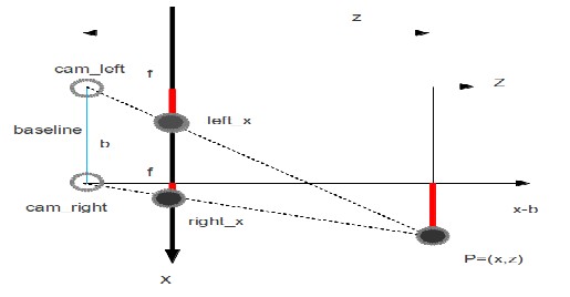
The difference between 3D location of the same points projected under two different views is called disparity.
d = left_x - right_x where d : disparity
left_x : position in left image rightt_x : position in right image
The optical axes of the two cameras are oriented parallel to each other. The z coordinate can be calculated by taking into consideration the following equations.
Let P(x,z) be the point in 3D space.Using the concept of similar triangles we get,
z = x z = x - b z = y = y
f left_x f right_x f left_y right_y where z : depth of the 3D point
f : focal length of camera lens
b : baseline (distance between two camera) (left_x,left_y) : point in left image (right_x,right_y) : point in right image
The location of the 3D point can be determined as follows :
x | = left_x * z | or | b + right_x * z |
------------- f | ------------------- f |
y | = left_y * z | or | right_y * z |
------------- f | ------------------- f |
z | = f * b | = | f * b |
------------------ | --------- |
IJSER © 2014 http://www.ijser.org
International Journal of Scientific & Engineering Research, Volume 5, Issue 1, January-2014 154
ISSN 2229-5518
left_x - right_x d
As this is a distributed system, involving processing and data gathering from multiple processors, there are certain delays involved in this. An image acquired from the BeagleBone Black should match with the image taken from the smartphone camera at the exact same time. This will mean that the 2 processes should happen in tandem. Following are the delays involved in our embedded system.
1. Processing delay
The amount of time required to process the images as per the above algorithm is the processing delay. It is the time that is required to construct a 3 dimensional image from 2 two dimensional images.
2. Propagation delay
Propagation delay is the amount of time that it takes to transfer images from the BeagleBone Black to the smartphone for processing. This depends on the webcam used, as well as the interface that is chosen between the BeagleBone Black and the smartphone. Serial communication over USB is faster than Bluetooth.
3. Queuing delay
It can so happen that the propagation delay is greater than the processing delay. Hence, the processor will have to wait before the next set of inputs is processed. In the case that the propagation delay is smaller than the processing delay, i.e. the rate at which our algorithm receives input is more than the speed at which it can process, then we will require a First In First Out queue to handle the flow of input in case of an overflow.
3D scanning has recently developed some very attractive products such as, Structure Sensor and ReconstructMe. Structure Sensor can be attached to the mobile and be used to capture 3D objects in digital form which can be used for many applications such as modeling, 3D printing and to mobile applications with 3D vision. Structure sensor comes with its SDK and also allows for wireless streaming.
ReconstructMe is a real-time 3D reconstruction software tool.It is based on the concept of obtaining a real- time 3D model of an object as opposed to a video stream. ReconstructMe is a paid software and comes with features like exporting the results to various CAD formats like STL, OBJ, 3DS,and PLY, performing reconstruction in metric space for a wide range of objects. The ReconstructMe SDK is supported on windows platform and shows best results with Kinect depth sensors.
A 3D scanner which is portable and made from off the shelf parts will be very easy to make changes to. This will help get a wider community base and will drive further innovation. Applications of a portable 3D scanning device include re creating museums virtually, reducing the expertise required in designing 3D objects for printing.
One of the main applications of such a device is to speedily build robots. Autonomous robots are required to build 3D
maps or localization and mapping. The use of off-the-shelf parts and programming environments (especially smartphone application development) which are already familiar to a large number of developers will help to reduce the amount of time to get started with building robots. Building robots from the ground up no longer remains restricted to industries or colleges.
The fact that we are using hardware which is mass produced, increases the cost/benefit ratio of the whole
idea. The key component here is to have hardware independent libraries and APIs. Future scope includes adding support for boards similar to BeagleBone Black as well as providing a well tested set of native libraries for different mobile operating systems. Additionally we can provide various interfaces between the hardware that is being used to
give additional freedom to the users.
IJSER © 2014 http://www.ijser.org
International Journal of Scientific & Engineering Research, Volume 5, Issue 1, January-2014 155
ISSN 2229-5518
In this paper, we highlight realistic 3D reconstruction methodology having varied applications. We discuss implementation of it on a distributed setup which attempts to provide an efficient method to capture the surroundings in three dimension and ways it can be processed to provide functionality for various applications.
The authors wish to thank Dr. Sarang Joshi. We would also like to thank Pune Institute of Computer Technology for providing space and infrastructure to help us with our efforts. This work was supported in part by a grant from Skylab Systems.
[1] “Obtaining Depth Information from Stereo Images”, IDS Whitepaper 3D Stereo Vision , 2012 [2] “Structure from Motion and 3D reconstruction on the easy in OpenCV
2.3+”, http://www.morethantechnical.com/2012/02/07/structure-from -motion-and-3d-reconstruction-on-the- easy-in-opencv-2-3-w-code/![]()
[3] http://www.cse.usf.edu/~r1k/MachineVisionBook/MachineVision.files/MachineVision_Chapter11.pdf
[4] ”Stereo and 3D vision”, http://courses.cs.washington.edu/courses/cse455/09wi/Lects/lect16.pdf
IJSER © 2014 http://www.ijser.org