International Journal of Scientific & Engineering Research, The research paper published by IJSER journal is about Simulation and Performance Investigation of Unified Power Quality Conditioner Using Hysteresis Current Control Method 1
ISSN 2229-5518
Simulation and Performance Investigation of Unified Power Quality Conditioner Using Hysteresis Current Control Method
Vikash Anand, Dr.S.K.Srivastava
Abstract - The simulation study of hysteresis controlled three phase unified power quality conditioner (UPQC) to improve power quality by compensating harmonics and reactive power required by a non-linear load is presented. UPQC consists of back to back connected Series And Shunt Active Filters, and is modeled with reference to a synchronously rotating d-q-o reference axes. The shunt active power filter compensates the source current harmonics and also it maintains the dc link voltage unchanged in steady state, while the series active power filter compensates the load voltage harmonics. This paper has proposed auto tuned UPQC maintains the THD well within the IEEE-519 standards. The results are found to be quite satisfactory to mitigate harmonics distortion, reactive power compensation and power factor improvement.
Keywords – Power System, Shunt Active Filter, Series Active Filter, Hysteresis Current Pulse Width Modulation.
1 INTRODUCTION
Harmonics contamination is a serious and a harmful problem in electric power system. Active power filtering constitutes one of the most effective proposed solutions. A UPQC that achieves low source current harmonics, low load voltage total harmonic distortion (THD), reactive power compensation and power factor correction is presented. Hence, it is necessary to reduce the dominant harmonics below 5% as specified in IEEE-519-1992 harmonic standard [9].
Harmonic Amplification is one the most serious problem. It is caused by harmonic resonance between line inductance and power factor correction (PFC) capacitors installed by consumers. Active filters for damping out harmonic resonance in industrial and utility power distribution systems have been researched [9]- [7].
Traditionally based, passive L-C filters were used to eliminate line harmonics in [1]-[13]. However, the passive filters have the demerits of fixed compensation, bulkiness and occurrence of resonance with other elements. The recent advances in power semiconductor devices have resulted in the development of active power filters (APF) for harmonic suppression.

Vikash Anand
M.Tech.(Pursuing)-Electrical Engineering Department. Madan Mohan Malviya Engineering College
Gorakhpur-273010(U.P), India
E-mail- srivastava.anand09@gmail.com
Dr. S. K. Srivastava
Associate Professor-Electrical Engineering Department
Madan Mohan Malviya Engineering College
Gorakhpur-273010(U.P), India.
E-mail- sudhirksri05@gmail.com
There are two major approaches that have emerged for the
harmonic detection [1], namely, time domain and the frequency domain methods. The frequency domain methods include, Discrete Fourier Transform (DFT), Fast Fourier Transform (FFT), and Recursive Discrete Fourier Transform
(RDFT) based methods. The frequency domain methods require large memory, computation power and the results provided during the transient condition may be imprecise [13]. There are several current control strategies proposed in the literature [7]-[2], [12]-[3], namely, PI control, Average Current Mode Control (ACMC), Sliding Mode Control (SMC) and hysteresis control. Among the various current control techniques, hysteresis control is the most popular one for active power filter applications. Hysteresis current control is a method of controlling a voltage source inverter so that the output current is generated which follows a reference current waveform in this paper[10].
In this paper, the proposed control algorithm for UPQC is applicable to harmonic voltage source loads as well as to harmonic current source loads. This control algorithm is applied under the basic concept of the generalized d-q-o theory. However, this generalized d-q-o theory is valid for compensating for the harmonics and reactive power using the parallel active power filter in the three-phase power system. To overcome such limits, a revised d-q-o theory is proposed. This revised algorithm may be effective not only for the three- phase three-wire UPQC with harmonic current, voltage loads, but also for the combined system of parallel passive filters and active filter[5].
This chapter basically deals with the modeling and design of UPQC for compensation of harmonics and reactive power. Designs of different parameters like power circuit, thyristor controlled capacitor banks, series active filter and shunt active filter are discussed.
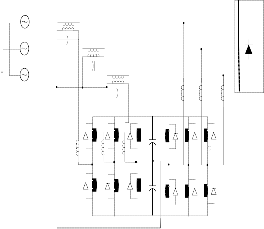
2 SERIES-SHUNT ACTIVE FILTER
As the name suggests, the series-shunt active filter is a combination of series active filter and shunt active filter. The topology is shown in Fig 1.The shunt-active filter is located at
IJSER © 2012 http://www.ijser.org
International Journal of Scientific & Engineering Research, The research paper published by IJSER journal is about Simulation and Performance Investigation of Unified Power Quality Conditioner Using Hysteresis Current Control Method 2
ISSN 2229-5518
the load side and can be used to compensate for the load harmonics. On the other hand, the series portion is at the source side and can act as a harmonic blocking filter. This topology is called as Unified Power Quality Conditioner. The series portion compensates for supply voltage harmonics and voltage unbalances, acts as a harmonic blocking filter and damps power system oscillations. The shunt portion compensates load current harmonics, reactive power and load current unbalances. In addition, it regulates the dc link capacitor voltage. The power supplied or absorbed by the shunt portion is the power required by the series compensator and the power required to cover
disturbance occurs. The DC link capacitor bank is divided into two groups connected in series. The neutrals of the secondary of both transformers are directly connected to the dc link midpoint [4]-[6]-[5].
The power system model considered can be divided into following units: the power supply system, series active filter and shunt active filter. These constituent members of the UPQC are modeled separately in this section. First consider the power supply system. By Kirchhoff’s law:

vif = ei - Ls - Rsiis - vih (1)
losses[11].
iis = iiL - iih
(2)
Va Ta
Vb
Where, subscript i refers to a, b and c phases in the power system; Ls and Rs are the inductance and resistance of the transmission line; vif is fundamental source voltage, ei is
n Tb
source voltage; vih
is the output voltage (harmonic voltage) of
Vc
Tc
Nonlinear
Loads
C1
the series active filter; iis is the line current; iiL is the load current and iis is the output current of the shunt of the shunt active filter respectively[2].
For the series active filter,
diis

vih = L1
dt
+ R1iis + d1ivc1 + (1- d1i)vc2
(3)
C2
Series Active Power
Filter
Shunt Active Power
Filter
Where, Ll and Rl are the leakage inductance and resistance of the series transformer, vc1 and vc2 are the voltages of dc link capacitors; dli is the switch duty ratio of the series active filter. Without loss of generality, the turn’s ratio of the transformer is assumed to be unity.
For shunt active filter:
Fig 1 Unified power quality conditioner topology
diih

2
dt
= R2iih -viF + d2ivcl + (1 - d2i) vc1 (4)
3. UNIFIED POWER QUALITY CONDITIONER
The UPQC has the capability of improving power quality at the point of installation on power distribution systems or industrial power systems. The UPQC, therefore, is expected to be one of the most powerful solutions to large capacity loads sensitive to
Where L2 and R2 are the leakage inductance and resistance of the shunt-connected transformer, d2i is the switch duty ratio of the shunt active filter. The turn’s ratio of this transformer is also assumed to be unity.
The two dc bus capacitor voltages can be described by the equations (5) and (6):
supply voltage flicker/imbalance[4]-[3].
dvc1
ic1 1
Elimination of supply voltage flicker, however, is


= = ( d1i iis -
d2i iih)
(5)
accompanied by low frequency fluctuation of active power flowing into or out of series active filter. The shunt active
filter performs dc link voltage regulation, thus leading to a
dt c1
c1 i=a,b,c i=a,b,c
dvc2
ic2 1
significant reduction of capacity of dc link capacitor.


= = [
(1- d1i)iis -
(1- d2i)iih] (6)
dt c2
c2 i=a,b,c i=a,b,c
3.1 Mathematical Modeling of UPQC
In this study, the power supply is assumed to be a three-phase, three-wire system. The two active filters are composed of two
3-leg voltage source inverters (VSI). Functionally, the series filter is used to compensate for the voltage distortions while the shunt filter is needed to provide reactive power and
counteract the harmonic current injected by the load. Also, the
3.2 UPQC Operating Principle
Distorted voltages in a 3-phase system may contain negative phase sequence, zero phase sequence as well as harmonic components. The voltage of phase "a" can be expressed as, in general[15]:
voltage of the DC link capacitor is controlled to a desired value by the shunt active filter. There can be negative and zero sequence components in the supply when a voltage
va = v1pa + v1na + v1oa+
Vkasin(kwt + ka) (7)
IJSER © 2012 http://www.ijser.org
International Journal of Scientific & Engineering Research, The research paper published by IJSER journal is about Simulation and Performance Investigation of Unified Power Quality Conditioner Using Hysteresis Current Control Method 3
ISSN 2229-5518
Where, v1pa is the fundamental frequency’s positive sequence
component while v1na and v1oa is the negative and zero
sequence components. The last term of equation (7),
vd
cos(ωt)
va

2
Vkasin(kwt + ka)
represents the harmonics in the
vq =
-sin(ωt) -sin(ωt -1200 ) -sin(ωt +1200 ) vb
3
voltage. In order for the voltage at the load terminal to be perfectly sinusoidal and balanced, the output voltages of the series active filter should be:
v0


1 1 1
2 2 2
vdp vdn 0 vdk
vc
vah = v1na + v1oa+
Vkasin(kwt + ka)
(8)
vqp + vqn + 0 + vqk
(12)
It will be shown how the series active filter can be designed to
0
0
v00
0
operate as a controlled voltage source whose output voltage would be automatically controlled according to equation (8).
Equation (12) shows that the fundamental positive sequence
components of voltages are represented by dc values in the d-
The shunt active filter performs the following functions:
q-0 frame. Here, p
is the phase difference between the
a) To provide compensation of the load harmonic currents
to reduce voltage distortions.
b) To provide load reactive power demand.
c) To maintain the DC-link voltage to a desired level.
To perform the first two functions, the shunt active filter acts as a controlled current source and its output current should include harmonic, reactive and negative phase sequence components in order to compensate these quantities in the load
positive sequence component and the reference voltage (phase "a”). For the proper functioning of a power supply system, it is desirable that the voltages at .the load terminal should be perfect sinusoids with constant amplitude. Even under a voltage disturbance, the load still requires a constant voltage. This means that when transformed to the d-q-0 axis, the load voltage become:
*
current. In other words, if the load current of phase "a" is expressed as:
vdF
vqF*

Vm
3 0
(13)
iaL = I1pm cos(ωt-θ1) +IaLn + ∑IaLk
= I1pm cosωt cosθ1+I1pmsinωt sin θ1+ IaLn + ∑IaLk (9)
v0F*
2
0
It is clear that the current output of the shunt active filter should be:
iah = I1pm sinωt sin θ1+ IaLn + ∑IaLk (10)
Where, Vm is the rated or desired voltage at the load terminal. Only one value, Vm, in the d-axis would be sufficient to represent the balanced, perfect sinusoidal, 3-phase voltages in the abc frame. Therefore vdp should be maintained at,
Hence, the current from the source terminal will be:

3 2Vm
while all the other components should be
ias = iaL – iah = I1pm cosωt cosθ1 (11)
This is a perfect, harmonic-free sinusoid and has the same
eliminated by the series active filter.
Similar expression can be obtained for the current
0 0

phase angle as the phase "a" voltage at the load terminal. The
id
cos(t ) cos(t 120 ) cos(t 120 ) ia
2
0 0
power factor is unity. It means that the reactive power of load
iq
3 sin(t )
sin(t 120 )
sin(t 120 ) ib
is not provided by the source.
i0


1 1 1
2 2 2
ic
3.3 UPQC Control Scheme

I1pm cos 1 I1nmcos(2ωt + n)
3
Ik cos(k -1)(ωt + k)
= I1pm sin 1 + -I1nmsin(2ωt + n) + Ik sin(k -1)(ωt + k)
It is clear from the above discussion that UPQC should first
2 0
0
0
separate out the fundamental frequency positive sequence
(14)
from the other components. Then it is necessary to control the
outputs of the two active filters in the way shown in equations (8) and (10) in order to improve overall power quality at the load terminal.
To solve the first problem, a synchronous d-q-0 reference frame is used. If the 3-phase voltages are unbalanced and contain harmonics, the transformation to the d-q-0 axes results in
Unlike load voltage, load current can change according to the connected loads. Therefore, it is not possible to assign it’s reference value. Instead, a new "moving time window" method is applied here to capture the active quantity of the fundamental positive sequence component which is expressed as a dc value in the d-axis. Furthermore, from equation (14), it is evident that the average of the other components, apart from I1pmcos 1 , in the d-axis is zero in one fundamental cycle
period because all of them are harmonics of the fundamental. Therefore a time window with a width of 0.02 seconds (for 50
Hz system) maybe selected to calculate the dc value. The
IJSER © 2012 http://www.ijser.org
International Journal of Scientific & Engineering Research, The research paper published by IJSER journal is about Simulation and Performance Investigation of Unified Power Quality Conditioner Using Hysteresis Current Control Method 4
ISSN 2229-5518
calculation for the first fundamental cycle is
1 T

id dt = I1pm cos 1 . After this, the window is moved
0
forward. If the moving frequency is also 50 Hz, the delay caused by the calculation is 0.02s. However if the moving frequency is n times of 50 Hz, the delay will be 0.02/n seconds. As the window moving frequency increases, calculation delay becomes shorter but the frequency at which the data moving into and out of the window is higher. Fortunately, in practical power systems, load current changes slowly. The two voltage-source inverters (VSIs) are used as the series and shunt active filters. The series active filter should behave as a controlled voltage source and its output voltage should follow the pattern of voltage given in equation (8). This compensating voltage signal can be obtained by comparing the actual load terminal voltage with the desired value vF*.Since the desired vF* is already defined, it is easy to calculate vh (= vF* - vs ) as vs is a known quantity. After obtaining the voltage signal vh, the switching duty ratio of the series active filter is obtained by giving this signal to the hysteresis controller. The shunt active filter acts as a controlled current source. It means that the inverter operates in the current-regulated modulation mode[3]-[6]-[14].
4 Simulation and Performance Investigation of UPQC
In this section the simulation analysis of UPQC is described for R-L load and the FFT analysis has been carried out simultaneously. In this two filters are used i.e. shunt active power filter and series active power filter.The shunt active power filter compensates for the source current harmonics and also it maintains the dc link voltage unchanged in steady state, while the series active power filter compensates for the load voltage harmonics.
4.1 Operation of Simulation Model
The operation of the simulation model shown below is described as – first the reference voltages and the reference currents are generated and then the reference voltages are compared with the actual load voltages and the reference currents are compared with the actual source currents and then the error signals are given to the hysteresis controllers for generating the switching signals for the switches of series active power filter and the shunt active power filter. And the generated pulses are then given to the series and shunt APF’s and accordingly the switches are turned on and off to compensate for the voltage and current harmonics.
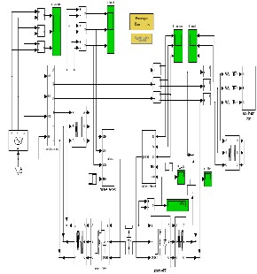
Fig.2 MATLAB model for Unified power quality conditioner (UPQC)
4.2 Simulation and Result Discussion
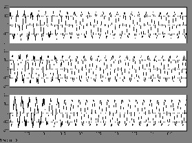
Fig.3 Load voltage before and after compensation
IJSER © 2012 http://www.ijser.org
International Journal of Scientific & Engineering Research, The research paper published by IJSER journal is about Simulation and Performance Investigation of Unified Power Quality Conditioner Using Hysteresis Current Control Method 5
ISSN 2229-5518
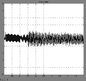
Fig.4 Compensating voltage for phase ‘A’
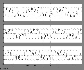

Fig.5 Load current
Fig.6 Source current before and after compensation
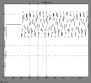
Fig.7 Compensating current for phase ‘A’
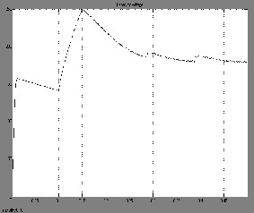
Fig.8 Capacitor voltage
IJSER © 2012 http://www.ijser.org
International Journal of Scientific & Engineering Research, The research paper published by IJSER journal is about Simulation and Performance Investigation of Unified Power Quality Conditioner Using Hysteresis Current Control Method 6
ISSN 2229-5518
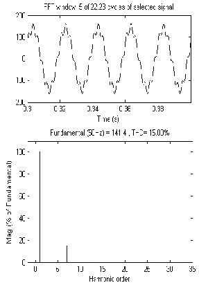
Fig.9 FFT analysis for source voltage
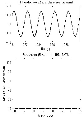
Fig.10 FFT analysis for load voltage
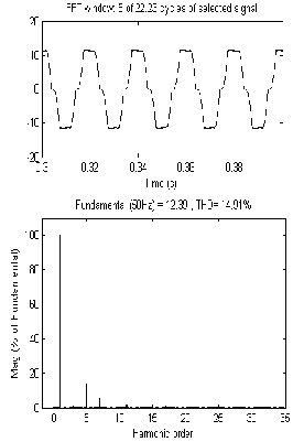
Fig.11 FFT analysis for load current
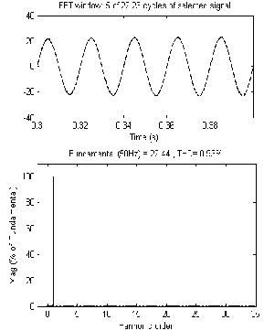
Fig.12 FFT analysis for source current
IJSER © 2012 http://www.ijser.org
International Journal of Scientific & Engineering Research, The research paper published by IJSER journal is about Simulation and Performance Investigation of Unified Power Quality Conditioner Using Hysteresis Current Control Method 7
ISSN 2229-5518
4.2.1 Result
Load Type | THD (%) Load Current | THD (%) Source Current |
R – L Load | 14.91 | 0.93 |
Table 1 THD analysis of Load and Source Current for R-L Load of UPQC
The table1shows that the THD analysis for the load current and the source current. It is clear from the table that the performance of the system improves and the THD is reduced up to very large extent.
Load Type | THD (%) Source Voltage | THD (%) Load Voltage |
R – L Load | 15 | 3.47 |
Table 2 THD analysis of Source and Load Voltage for R-L Load of UPQC
The table2 shows that the THD analysis for the source voltage and the load voltage. It is clear from the table that the performance of the system improves and the THD is reduced up to very large extent.
5 CONCLUSION
A MATLAB based model for the UPQC has been simulated
Active Filters”, IEEE Transaction on power electronics. Vol.13. No 2 march 1998, pages: 494-501
[7] M. Kazmierkowsi, L.Malesani, Current Control Techniques for Three
Phase Voltage Source PWM converters: A survey, IEEE Trans on
Industrial Electronics, vol.45, no.5, pp.691- 703, October 1998.
[8] M.H. Rashid, Power Electronics, Circuits, Devices, and Applications 2nd
ed., Prentice Hall 1993 “An exploration of the state-of- the-art in power
conversion techniques and power semiconductor devices.”
[9] Roger C.Dugan, Mark F. McGranaghan, Surya Santo so and H.Wayne
Beaty, Electrical Power System Quality, McGraw –Hill.
[10] S. Buso, L. Malesani, P. Mattavelli, Comparison of current control
Techniques for Active power Filter Applications, IEEE Transactions on
Industrial Electronics, Vol.45, no.5, pp.722-729, Oct 1998..
[11] Yunping Chen, Xiaoming Zha*Jin Wang, Huijin Liu, Jianjun Sun and
Honghai Tang “Unified Power Quality Conditioner (UPQC): The
Theory, Modeling and Application” an IEEE paper -2000.
[12] V. Agelidis, M. Calais, Application specific harmonic performance
evaluation of multicarrier PWM techniques, IEEEPESC’ 98 Conference
Record, pp. 172-178, 1998.
[13] Y.Sato, T.Kawase, M.Akiyama, and T.Kataoka, A control strategy for general – purpose active filters based on voltage detection, IEEE Trans.
Ind. Appl., vol. 36, no.5, pp.1405–1412, Sep / Oct.2000
[14] Donghua Chen; Shaojun Xie; “Review of the control strategies applied to active power filters”; Electric Utility Deregulation, Restructuring and
Power Technologies, 2004. (DRPT 2004). Proceedings of the 2004
IEEE International Conference on, Volume 2, 5-8 April 2004
Page(s):666 - 670 Vol.2
[15] Jain, S.K.; Agarwal, P.; Gupta, H.O.; “A control algorithm for compensation of customer-generated harmonics and reactive power”; Power Delivery, IEEE Transactions on, Volume: 19, Issue: 1, Jan. 2004
Pages: 357 – 366.
APPENDIX
The values of different parameters used for UPQC have been given below.
Source voltage: 3-phase, 100V, 50Hz.
for R-L load using hysteresis control technique. The
Harmonics in the supply voltage: 5th
, 0.2pu and 7th, 0.15pu.
simulation results show that the input voltage harmonics and the current harmonics caused by non-linear load are compensated very effectively by using the UPQC.
REFERENCES
[1] Bhim Singh, Kamal Al Haddad and Ambrish Chandra, A Review of Active Filters for Power Quality Improvement, IEEE Trans on Industrial Electronics, Vol.46, No.5, October 1999, pp. 960-970..
[2] E.E.EL-Khoy, A. EL-Sabbe, A.El-Hefnawy, and Hamdy M.Mharous, Three phase active power filter based on current controlled voltage source
inverter, Electrical Power and Energy Systems, 28 (2006), 537-547.
[3] G. Carrara, S. Gardelta, M. Marchesoni, A new multilevel PWM method:
theoretical analysis, IEEE Trans. On power electronics Vol. 7. No. 3,
July, pp.497-505, 1992.
[4]V. Khadkikar, P. Agarwal, A. Chandra, A.O. Barry and T.D. Nguyen; “A Simple New Control Technique For Unified Power Quality Conditioner
(UPQC)”; 11th International Conference on Harmonics and Quality of
Power-2004, pages: 289-293.
[5] M Vilathgamuwa, Y H Zhang., and S.S.Choi; “Modeling, Analysis and Control of Unified Power Quality Conditioner”; 8th International Conference on Harmonics and Quality of Power ICHQP '98, by IEEE/PES and NTUA, October I4-16, 1998, pages: 1035-1040.
[6] Hideaki Fujita, Member, IEEE and Hirofumi Akagi, Fellow, IEEE, “The
Unified Power Quality Conditioner: The Integration of Series and Shunt
Proportional gain Kp: 0.5 and Integral gain Ki:10
Capacitor reference voltage: 300V
Series transformer rating: 1kVA, 50Hz, 240/240V
RL load parameters :10 Ω, 100mH
Line parameters : 0.2 Ω, 1.5mH
RC filter parameters : 16 Ω, 199.04μF
Hysteresis band gap : -0.01 to 0.01
IJSER © 2012 http://www.ijser.org