International Journal of Scientific & Engineering Research, Volume 4, Issue 8, August-2013 913
ISSN 2229-5518
Simulation of Sensorless Control of PMSM based on Zero-Sequence Carrier Injection with Improved Speed Estimation
Meera E., Prathibha P.K.
—————————— ——————————
he permanent magnet synchronous motor (PMSM) has been widely used in industrial applications due to its high performance characteristics. In the high-performance variable speed and precise position control applications, high- resolution rotor position information is required to execute field-oriented control algorithm. As a result, a resolver or encoder attached to the shaft of the rotor is typically used. These position sensors, however, increase the cost, inertia, and size of the PMSM drive system. Elimination of the shaft position sensor from the PMSM applications has resulted in
the development of several techniques.
Sensorless control refers to a special type of motor control where the rotor position sensor is replaced by a mathematic algorithm which uses information from other sensors such as current sensors and voltage sensors.
An electromotive force (EMF) model has been used to
estimate the rotor position and speed [1]. The rotor’s position is contained in the EMF of the motor. The disadvantage of this method is that it involves complicated computations to obtain the EMF of the motor. Also this method cannot be used at low speed or standstill since EMF would be zero. A nonlinear observer has been proposed to estimate rotor position and speed. This method is dependent on mechanical parameters and noise [2].
An injecting-signal method has been used to detect the rotor position of the PMSM. This estimating method is not affected by the motor speed and load. This method uses the
————————————————
• Prathibha P.K is assistant professor,Electrical and Electronics Engineering
department of Rajagiri School of Engineering and Technology, India. She
holds masters degree in power system from College of Engineering,
Trivandrum. E-mail prathibhapk@ragiritech.ac.in
inductance variation with rotor position or magnetic saliency for estimating rotor position. Magnetic saliency can be caused either due to saliency of interior rotor or by saturation of stator iron by the rotor flux as in surface mounted PMSM. A high frequency voltage carrier signal is superimposed on the fundamental excitation. This injected signal interacts with the machine saliency and causes phase or amplitude modulation in the resulting current response. The modulated response signal is processed to extract rotor position information.
The carrier can be a rotating vector, alternating vector or
inherent high frequency component of pulse width modulator. The carrier is usually injected in d-q components. When an external carrier is injected along d-q component [3], the response to this signal interacts with current controller and system performance is affected.
In this paper, the inherent high frequency zero-sequence component produced by space vector modulation is used as carrier. The response to zero sequence voltage is evaluated from αβ currents are used to obtain rotor position. The carrier frequency will be the same as switching frequency. This method provides higher sensitivity. The signal processing involved for position estimation is simple. For improved speed estimation, a phase- locked loop observer is proposed. This provides fast decay of position error to zero and eliminating additional filters.
Consider the model of PMSM in stationary reference frame αβ0. For high frequency analysis, a reduced model is adopted by neglecting fundamental frequency terms. Also the high frequency resistive voltage drop is neglected. Thus, the voltage equation can be written as follows:
IJSER © 2013 http://www.ijser.org
International Journal of Scientific & Engineering Research, Volume 4, Issue 8, August-2013 914
ISSN 2229-5518
![]()
u = L di dt
where L is the inductance matrix and
u = [uα uβ
(1)
T
0
The implementation of this technique will be carried out using two current regulators, one for the direct-axis component and another for the quadrature-axis component, and one speed regulator [4].
and
i = [iα iβ
i ]T
are the voltage and current vectors
Three phase stator currents are transformed into d-q coordinates using Clarke and Park transformation. These
respectively.
In surface mounted PMSM, magnetic saliency is produced
by the saturation effect of the stator core, due to the
currents are used as feedback for the current control loop.
Clarke transformation:
i
permanent magnet flux. The inductance matrix can be
obtained as function of rotor position.![]()
iα
i =
2 1 1
![]()
3 0 3
1 a
![]()
3 ib
La − Lb cos(2θ )
− Lb sin(2θ )
Lb cos(2θ )
β
2 2 i
(7)
Park transformation:
L =
− Lb sin(2θ )
La + Lb cos(2θ )
− Lb sin(2θ )
id
cosθ
sinθ iα
![]()
2 Lb
cos(2θ )
![]()
− Lb
sin(2θ )
![]()
4 La
i
=
sinθ
cosθ
i
q −
β
(8)
(2) where La and Lb are functions d-axis inductance, Ld and q- axis inductance, Lq.
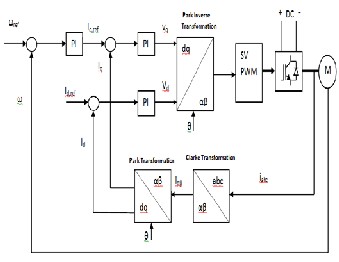
In the outer speed loop, the reference speed is compared with the measured speed and the error signal is fed to the speed PI controller as shown in Fig. 1. The output is the![]()
L = 1 (L
a 2 d
L = 1 (L
+ Lq )
− L )
(3)
torque command which is proportional to the q-axis current. The error between reference currents, iqref and idref , and measured currents, iq and id are fed to PI controllers to obtain![]()
b 2 q d
(4)
phase voltage, Vqref and Vdref along q-axis and d-axis
respectively. The phase voltages are converted to α-β
La is the average inductance and Lb defines inductance
fluctuation.
coordinate system using inverse Park transformation. Inverse Park transformation:
The current can be solved from (1), as follows
iα
cosθ
− sin θ id
di = L−1u
i = sin θ
cosθ
i
![]()
dt (5)
β
q
(9)
For motors with low saliency i.e., Lb << La, the inverse inductance matrix can be approximated as,
There are many torque control strategies and the goal for all of them is to maintain a linear control over the torque[5].
La + Lb cos(2θ )
Lb sin(2θ )
− 4Lb cos(2θ )
One of the easiest strategies and most widely used in the
L−1 = =1
L2
Lb sin(2θ )
La − Lb
cos(2θ )
4Lb
sin(2θ )
industry is Constant Torque Angle (CTA) control. The torque angle is defined as the angle between the q-axis current and
a −
2Lb
cos(2θ )
2Lb
sin(2θ )
4La
the rotor permanent flux. This angle is maintained at 900 in
(6) When zero-sequence voltage is applied, the upper right sub- matrix is considered and the position dependent terms have higher amplitude of 4Lb. Thus by applying a zero sequence carrier we obtain a position dependent signals which is four times higher than injecting a non-zero sequence carrier.
Field oriented control of PMSM is one important variation of vector control methods. With the information of the stator currents and the rotor angle a FOC technique can control the motor torque and the flux in a very effective way. The main advantages of this technique are the fast response and the little torque ripple.
this control strategy. For this d-axis current is maintained at
zero, so the torque depends only on the amplitude of q-axis
current. The main advantage of this control strategy is that it
IJSER © 2013 http://www.ijser.org
International Journal of Scientific & Engineering Research, Volume 4, Issue 8, August-2013 915
ISSN 2229-5518
simplifies the torque control mechanism.
where lij are scalar components of inverse inductance matrix given in (6).
Then these signals are demodulated as follows
k
iα ,demk
= iα ,difk (−1)
k
(13)
iβ ,demk = iβ ,difk (−1)
The demodulated current is obtained as
iα ,demk = l13u pTs
iβ ,demk = l23u pTs
(14)
(15) (16)
By substituting values for the l13 and l23 from the inductance matrix (6), we get demodulated currents as function of sine and cosine terms.
Fig. 1: Block diagram of field oriented control![]()
iα ,demk = −rp cos(2θ )u pTs
iβ ,demk = rp sin(2θ )u pTs
(17) (18)
r = 4L L2
In general, high frequency signal injection based sensorless
control methods include 3 steps:
where p
b a .
1. Signal injection
By using atan2 function, we obtain double the rotor position.
2. Demodulation process
3. Speed and position estimation
2θ k
= a tan 2(i
β ,demk
,−iα ,demk )
(19)
Estimation of rotor position is performed by applying a voltage carrier in the zero sequence and evaluating the current response in the α and β components[6].
The voltage signal is injected along zero sequence component when voltage along α and β components are zero. The high frequency zero sequence voltage is naturally generated by an inverter, when controlled with space vector pulse width modulation (PWM). For this, the neutral point of the motor is connected to the midpoint of dc link capacitor through a filter. The carrier frequency is same as switching frequency.
To obtain rotor information the current response is sampled at instants t = (1/2)kTs , where Ts is the swiching period and k = 0,1,...etc. The current response along α and β components at the sampling instant is zero. The voltage equation at sampling instants is given by
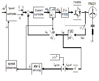
The angle obtained after limiting within π radians is divided by two to achieve the electrical rotor position. A combination of high pass filter and low pass filter is used for filtering of demodulated current. The estimated angle is used for reference frame transformation and also for estimating motor speed.
The block diagram of the sensorless control scheme is shown in Fig. 2. The basic drive of the PM synchronous motor is based on field oriented control. The neutral of the motor is connected to midpoint of dc link capacitor through an LC filter in order to inject the carrier. The demodulated and filtered signal is fed to atan2 function. After unwrapping and dividing by two the electrical angle is obtained.
u = [0,0, u
(−1)k ]T
(10)
where up is the amplitude of zero- sequence voltage.
By substituting (10) in (5), we obtain current derivative as
k
iα ,difk
= l13u pTs (−1)
k
(11)
iβ ,difk = l23u pTs (−1)
(12)
IJSER © 2013 http://www.ijser.org
International Journal of Scientific & Engineering Research, Volume 4, Issue 8, August-2013 916
ISSN 2229-5518
Fig. 3. The proposed PLL observer
Fig. 2. Block diagram of sensorless control of a PMSM drive
In order to estimate speed from rotor position, usually rotor angle is differentiated. But this would result in noise disturbance. Another approach to estimate speed is done using a speed observer using motor mechanical parameters. Here we use a non linear observer which operates similar to a phase-locked loop (PLL) for further refining of position and estimation of speed.
A PLL is a device which locks an output signal phase
relative to an input reference signal phase. PLL observer finds
wide application in industrial servo drives [7].Here, the error between the rotor position obtained by atan2 function and estimated position is fed to PI controller.
The error signal can be given by,
^
ε = sin[m(θ − θ * )]
where m=2 for saliency based position estimation methods.
^
For small errors, ∆θ = θ − θ * ≅ 0 ,
sin ∆θ = ∆θ
The output of the PI controller is the estimated speed. The speed is integrated to obtain rotor position.
The simulation of above mentioned sensorless control technique is done using software tool PSIM. The parameters of PMSM used for simulation is given in Table 1.
Table 1: Motor Parameters
Stator Resistance, Rs | 2.875Ω |
d-axis inductance, Ld | 8.5mH |
q-axis inductance, Lq | 10.34mH |
Poles, P | 8 |
Moment of inertia, J | 0.0008kgm2 |
Friction coefficient, B | 0.001Nms |
The whole system is composed of the controller block, the motor block, the inverter and the reference frame transformation blocks. The switching frequency of inverter is
5 kHz.
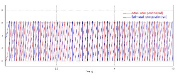
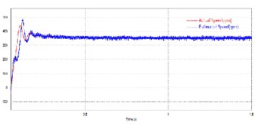
Motor is run at reference speed of 350 rpm. The load torque is given as 1Nm. Fig. 4 shows that the estimated rotor position follows the actual rotor position with a time delay. Fig. 5 shows that estimated speed is in agreement with the actual motor speed.
The PI controller value in PLL observer is taken as Kp=310
and Ki = 3. Fig. 6 shows that PLL output position exactly
tracks the PLL input position.
ω* = k
=k
ε
s
![]()
θ * = ω
(21)
s (22)
The estimated speed is used as feedback for the speed controller of the drive system. By using PLL, proper tracking of actual rotor position by the estimated position is obtained.
Fig. 4. Waveform of rotor position in radians
IJSER © 2013 http://www.ijser.org
International Journal of Scientific & Engineering Research, Volume 4, Issue 8, August-2013 917
ISSN 2229-5518
sequence excitation is used here, it does not interact with current controller and thus reduce torque pulsation. Also, with carrier frequency same as switching frequency, there are no additional noise produced and system is highly sensitive. A PLL observer is used to estimate motor speed. It provides a filtered position and fast settling of motor speed. This is validated using simulation results.
Fig. 5. Speed waveform of motor
Fig. 6. Waveform of PLL input and PLL output
In this paper, a sensorless control method using carrier injection is discussed. The zero-sequence component produced by space vector PWM is used as carrier. Since zero-
[1] Z. Chen, M. Tomita, S. Doki, and S. Okuma, “An Extended Electromotive Force Model for Sensorless Control of Interior Permanent-Magnet Synchronous Motor,” IEEE Trans. Ind. Electron., vol. 50, no. 2, pp. 288–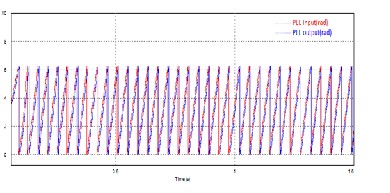
295,Apr. 2003.
[2] G. Zhu, A. Kaddouri, L. A. Dessaint, and O. Akhrif, “A Nonlinear State Observer for the Sensorless Control of a Permanent-Magnet ac Machine,”IEEE Trans. Ind. Electron., vol. 48, no. 6, pp. 1098–1108, Dec. 2001.
[3] M. Linke, R. Kennel, and J. Holtz, “Sensorless Speed and Position Control of Synchronous Machines using Alternating Carrier Injection,” in Proc. IEEE IEMDC, Madison, WI, Jun. 2–4, 2003, pp. 1211–1217.
[4] David Vindel Muñoz,Design, “Simulation and Implementation of a PMSM Drive System”,M.Eng Thesis, Chalmer University of Technology,Sweden,May 2011.
[5] R. Krishnan, Electric Motor Drives:Modeling,Analysis and
Cnotrol, New Jersey: Prentice Hall, 2001, ch. 9.
[6] R. Leidhold and P. Mutschler, “Sensorless Position Estimation by using the High Frequency Zero- Sequence Generated by the Inverter,” in Proc. 35th IEEE IECON, 2009, pp. 1282–1287.
[7] L. Harnefors and H.-P. Nee, “A General Algorithm for Speed and Position Estimation of ac Motors,” IEEE Trans. Ind. Electron., vol. 47, no. 1, pp. 77–83, Feb. 2000.
IJSER © 2013 http://www.ijser.org