There has been proposed many methods in the literature that use
above concept i.e. adding some code or redundancy bits to the transmitting signal.
International Journal of Scientific & Engineering Research, Volume 4, Issue 4, April-2013 334
ISSN 2229-5518
Simple Error Detection Method
Sachin Gupta
Student of School of Electronics Engineering, VIT University, Vellore – 632014, Tamil Nadu, India schngupta345@gmail.com; +91-9092885094
Abstract—
In any communication system, the received signal will differ from the transmitted signal due to various transmission impairments. For analog signals, these impairments introduce various random modifications that degrade signal quality. For digital signals, bit errors are introduced: A binary 1 is changed into a binary 0 and vice versa. Increase in data rate of a digital transmission system increases the bit error rate. Longer the digital data, the more bits it has and the probability that one of these bits is in error increases.
At the receiving end of a digital transmission system, it is always desirable to receive data with fewer bit errors. This motivates the use of error- detection techniques. Various types of error detection techniques and codes are used. Some are used for detection of single bit errors and some are for burst errors or multiple bit errors.
In this paper, a simple error detection technique is proposed by which a receiver can easily detect most types of bit errors i.e. both single bit and multiple bit errors. The proposed technique is based on a basic arithmetic operation i.e. counting. By counting the total number of 1’s and
0’s in the binary data to be transmitted, we can detect the errors in the received data. The performance of the proposed simple error detection technique is evaluated by comparing it with the existing techniques i.e. parity check, Cyclic Redundancy Check (CRC) and checksum. This paper also discusses about the shortcomings of this simple error detection technique.
Index Terms—
Burst error, Cyclic Redundancy Check (CRC), Checksum, error detection, multiple bit errors, Parity check and single bit error.
—————————— ——————————
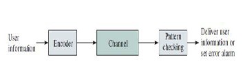
In data communication systems, an error occurs when binary 1 is transmitted and binary 0 is received, or binary 0 is transmitted and binary 1 is received. Two general types of error can occur: single-bit error and burst errors or multiple bit errors. A single-bit error is an isolated error condition that alters one bit but does not affect nearby bits. But a burst error of length N is a contiguous sequence of N in which first and last bits and any number of intermediate bits are re- ceived in error. The main function of error detection is to make the probability of a receiver passing up an incorrect frame to the client very, very small. Error detection is performed by calculating an er- ror-detecting code that is a function of the bits being transmitted. The code is appended to the transmitted bits. The receiver calculates the code based on the incoming bits and compares it to the incoming code to check for errors. The general block diagram of an error de- tection system is as shown in figure 1.
There has been proposed many methods in the literature that use
above concept i.e. adding some code or redundancy bits to the transmitting signal.
Some of these methods are parity check, Cyclic Redundancy Check (CRC) and checksum. In parity check, parity concept is used which appends one extra bit for making the number of 1’s even for even parity and odd for odd parity in the message being transmitted. In CRC, at transmitter side, data is divided by a given generating poly-
nomial, quotient is discarded and remainder is appended at the end of
IJSER © 2013 http://www.ijser.org
International Journal of Scientific & Engineering Research, Volume 4, Issue 4, April-2013 335
ISSN 2229-5518
message. In checksum, we sum all the data or numbers that are being sent and append the complement of this sum to the data at the trans- mitter side. But in the proposed simple error detection method, there is no need for extra code to be appended to the message binary data. We just only need to use one flag in between the binary data so that receiver will come to know about the numbers of ones and zeros in the sent data.
Here we discuss about the development of this simple error detection technique. The following steps are involved at transmitter site and at receiver site.
Consider the binary data that has to be sent. Count the number of ones and zeros in the data. After counting the number of ones and zeros, assume any flag that should be known to both receiver and transmitter and insert it in the bit position that is just after the total number of zeros in the message. Alternately we can also insert the flag in the bit position that is just after the total number of ones in the message. The transmitter and receiver should also agree in advance on the issue of inserting a flag after total number of ones in the bina- ry message or after total number of zeroes in the binary message.
After passing through the channel, the data is received by receiver. Receiver will start counting the number of bits until it comes across the flag. Once the receiver encounters the flag it stops counting and drops the flag. The count value is taken to be equal to total number of zeros in the received binary message. Then it again starts counting the total number of ones and zeros in the binary message after drop- ping the flag. Now it compares the total numbers of zeros that we counted before and after dropping the flag. If numbers match then we can conclude that the received message is error free otherwise the received message is erroneous. Alternately same procedure can be followed for number of ones in the received data.
So, in this way this method works in detecting the errors in the re- ceived message.
A simulation of this simple error detection method is done by using
MATLAB software. And following results are shown for different types of bit errors.
IJSER © 2013 http://www.ijser.org
International Journal of Scientific & Engineering Research, Volume 4, Issue 4, April-2013 336
ISSN 2229-5518
Let us consider 20-bit binary data and encode the data by inserting a flag ‘5’at the bit position after total number of zeros in the binary message. It is assumed that at the 4th position, a bit undergoes a change from 1 to 0 as it travels through the channel. And at the re- ceiver site total numbers of zeros are counted as the total number of bits before the position of the flag (count of zeros before dropping of flag: 9).Then the flag is dropped. After dropping the flag, total num- bers of zeros are counted in the whole received signal (count of ze- roes after dropping of flag: 10). Since both the count values are dif- ferent we detected that an error has occurred during transmission. Graphical view of detection of single bit error is given below.
Let us consider 30-bit binary data and encode the data by inserting a flag ‘5’at the bit position after total number of zeros in the binary message. It is assumed that at 3th, 5th, 9th, 24th, 29th, position bits are altered as it travels through the channel. And at the receiver site total numbers of zeros are counted as the total number of bits before the position of the flag (count of zeros before dropping of flag: 15).Then the flag is dropped. After dropping the flag, total numbers of zeros are counted in the whole received signal (count of zeroes after drop- ping of flag: 18). Since both the count values are different we detect- ed that error has occurred during transmission. Graphical view of
detection of multiple bit errors is given below.
Let us consider 50-bit binary data and encode the data by inserting a flag ‘5’at the bit position after total number of zeros in the binary message. It is assumed that from the 5th to 20th position, bits are changed to 1, as the data travels through the channel. And at the re- ceiver site total numbers of zeros are counted as the total number of bits before the position of the flag (count of zeros before dropping of flag: 31).Then the flag is dropped. After dropping the flag, total numbers of zeros are counted in the whole received signal (count of zeroes after dropping of flag: 21). Since both the count values are different we detected that error has occurred during transmission.
Graphical view of detection of burst errors is given below.
IJSER © 2013 http://www.ijser.org
International Journal of Scientific & Engineering Research, Volume 4, Issue 4, April-2013 337
ISSN 2229-5518
We observed the above simulation results and from that we can con- clude the simplicity of this method in detecting the different types of errors. And we can also compare this method with the existing meth- ods i.e. parity check, CRC, checksum. The parity check method can- not detect errors when even number of changes occurred. The CRC method uses redundancy bits and perform division operation in both site i.e. transmitter and receiver. For long message it takes more time and implementation of CRC is complex. The checksum also uses redundant bits. If the binary message stream is large then it needs more redundant bits to detect errors and takes much time at the re- ceiver side for error detection. But in this simple error detection method there is no use of redundant bits and it is very simple to im- plement. Computational rate is high because of using a basic arith- metic operation i.e. counting. And it takes very little time to detect the errors. This technique works efficiently irrespective of the length of binary message. There is only one shortcoming of this method that is mentioned below.
This is very simple method and based on arithmetic operation count- ing. In most of the cases it works well. But when even number of one’s change to zeros and even number of zeros change to one’s, this technique fails to detect errors (for example, two 1’s are changed to
0’s and two 0’s are changed to 1’s. In this case total number of zeros and ones will remain same in the binary data and we’ll not be able to detect the errors).
A simple error detection method has been proposed and simulation results have been discussed in this paper. We have also discussed about the performance of this method by comparing it with the exist- ing methods and short coming of this method is also investigated.
[1] Behrouz A. Forouzan, “Data Communication and Networking”,
3rd Edition, Tata McGraw Hill, 2004.
[2] William Stallings, “Data and Computer Communications”, 8th
Edition, Pearson Education, 2007.
[3] A. Leon-Garcia, Indra Widjaja, “Communication Networks”, 2nd
Edition, Tata McGraw-Hill, 2004.
IJSER © 2013 http://www.ijser.org