International Journal of Scientific & Engineering Research, Volume 4, Issue 10, October-2013 580
ISSN 2229-5518
Self power generated Ultra Low Power Microcontroller based Gait aided Functional Electrical Stimulator
S.Ramanan
Abstract- This paper proposes the design and implementation of the functional electrical stimulator using the ultra low power microcontroller MSP430 , which restores the functionality of paralyzed portion of human body due to spinal cord injury (SCI) that consumes the power supply generated by the body. FES stimulates muscles enough to make them contract. FES strengthens muscles, relaxes then and improves their function. This system removes the drawback of suppressing skin breakdown and itching and reduces power consumption. This device uses fully programmable symmetric biphasic pulses with inter-pulse interval for surface electrodes and it works in both modes: open loop as well as closed loop. A MSP430 microcontroller which operates at low power consumption is used for control of stimulation parameters such as stimulation frequency, pulse width, inter-pulse duration and pulse amplitude, provides higher currents used for gait analysis. EMG signals are recorded by sensors for closed loop operation and in open loop it operates by use of push buttons and LCD display. The power supply generated by the use of thermocouples that produces power supply from the body heat generation.
Index Terms- Electrical Stimulation, feedback system, FES, Gait Analysis, microcontroller, power supply, thermocouple, ultra low power mode,
1 INTRODUCTION
A stimulator is an electronic medical device which is used to produce the excitement of muscles and nerves. The excitement in terms defined as the change in the characteristics of the normal state of the muscle or nerve based on the application of area. The stimulation not only produces the abrupt change of normal state of muscles and nerves but also helps
to recover the normal functioning of the damaged
muscles and nerves. Hence it is used as one of the therapeutic equipment too. Though there are many therapeutic equipments present in healthcare, the stimulator ranks the first in recovering the functions of the damaged organs of the body. Since it is minimally invasive technique, it is used in the healthcare for treatment. Functional Electrical Stimulator [FES] is used not only in treatment of patients but also used in gait restoration and neuro rehabilitation especially in walking and prosthetic controls. Using new microcontrollers with integrated memory modules and peripherals, it is possible to design single-chip controlled stimulators. In [1] the FES is designed only for walking and standing but it can be programmed to perform various applications. To recover the arms and limbs from stroke or any other disorders, the system must have atleast four channels [3]. In this proposed system, we use low power consumable microcontroller MSP430 for controlled stimulations that uses the power generated by thermoelectric generators of human body [6].The human body is a tremendous store house of enegy. While sitting it possess around 116W of energy which is enough to light a tube light or run a laptop. In our proposed system we have used the power generated from the body heat to the low power microcontroller to produce electrical pulses of stimulations.

Ramanan.S , Final Year Student in Biomedical Engineering, Adhiyamaan College of Engineering, Hosur, TamilNadu, India.
Email id: ramananbiomedical@gmail.com
2 NEED OF THE STIMULATOR
The stimulator integrates an easy to program interface. The stimulator is for use with surface electrodes. The stimulator supports state control and it supports sensory inputs and complex patterns of
stimulation [4]. Inorder to produce the change of normal state of the muscle or nerve, it is necessary to apply an external source of energy. For this purpose we are applying the electrical pulses of periodic intervals, with some required intensity of currents that depends upon the area of application.
3 CONDITION AFTER STIMULATION
Normally human body have the nerve and muscle in the resting potential state, which is characterized by the movement of Na+ ions from inside to outside of the cell and movement of K+ ions
from outside to inside of the cell. After application of stimulation, the nerves or muscles will lose their normal nature and the excitable state is attained that produces effects of nerve and muscular depolarizations, which is the change of resting potential to the action potential, that is characterized by the movement of Na+ ions inside of the cell and K+ ions outside of the cell. Stimulus must have adequate intensity and last long enough to equal or exceed membrane's basic threshold for excitation. Stimulus must alter membrane so that a number of ions are pushed across membrane exceeding ability of the active transport pumps to maintain the resting potentials thus forcing membrane to depolarize resulting in an action potential.
4 NEED OF THE ULTRA LOW POWER MICROCONTROLLER
Ultra low power microcontroller MSP430 is
used in this proposed system that removes the
IJSER © 2013 http://www.ijser.org
International Journal of Scientific & Engineering Research, Volume 4, Issue 10, October-2013 581
ISSN 2229-5518
drawback of the over consumption of power supply. The timer of the controller is programmed to deliver the electrical pulses at negligible time intervals with various intensity levels of the current [5]. The previous existed systems have various drawbacks which produces different activities like muscle twitch, that can be easily removed by this system by use of programmable microcontroller that delivers biphasic waveforms of currents. This system is further advanced to wireless operated stimulating device with the connection of USART connection to wireless medium or use of class E amplifier that transmits power to RF transmitter and RF receiver with controller part receives the power from it. The self power is generated by the human body which is extracted by the heat produced in the body. For the generation of electricity from the heat produced in the body, in this system we are using the thermopiles or greater number of thermocouples that works on the principle of Seeback Effect that states there will be the production of electrical potential difference due to the difference in temperature.
5 BLOCK DIAGRAM APPROACH
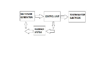
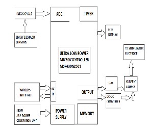
The proposed system consists of the above block diagram which comprises the 3 parts namely the self power generation part, microcontroller part and feedback system. The self power generation system consists of the thermocouples that is used as a wearable band in the wrist. The MSP430 microcontroller used in this system has the memory, interface, Analog to digital converter, Timer. The feedback unit comprises of electromyogram sensors, that extracts signal from the body and transmits the signal to the amplifier circuit that amplifies the analog signals to feed them to the ADC of the microcontroller. The analog signals are converted to digital signals further they are converted to analog signals by DAC that connects to current source. The current source provides the stimulation signals to the patient through the stimulation electrodes. The stimulation is periodically provided by resetting the timer signals and watch dog timer in the controller programming in the microcontroller.
6 SELF POWER GENERATION UNIT
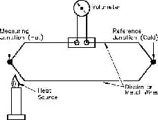
The self power generation unit consists of the Thermoelectric generators [TEG] which has the large number of thermocouples, that operates on the principle of Seeback Effect. Mostly these TEGs are connected in series to convert the heat effect to electric power [6].
Fig2. Explains the Seeback Effect
The power obtained from the thermocouples is fed to the controller unit where the power is consumed to produce the function of stimulation.
In a thermoelectric material there are free electrons or holes which carry both charge and heat. To a first approximation, the electrons and holes in a thermoelectric semiconductor behave like a gas of charged particles. If a normal (uncharged) gas is placed in a box within a temperature gradient, where one side is cold and the other is hot, the gas molecules at the hot end will move faster than those at the cold end. The faster hot molecules will diffuse further than the cold molecules and so there will be a net build up of molecules (higher density) at the cold
end. The density gradient will drive the molecules to diffuse back to the hot end. In the steady state, the effect of the density gradient will exactly counteract the effect of the temperature gradient so there is no net flow of molecules [7]. If the molecules are charged, the buildup of charge at the cold end will also produce a repulsive electrostatic force (and therefore electric potential) to push the charges back to the hot end. The electric potential (Voltage) produced by a temperature difference is known as the Seebeck effect and the proportionality constant is called the Seebeck coefficient. If the free charges are positive (the material is p-type), positive charge will build up on the cold which will have a positive potential. Similarly, negative free charges (n-type material) will produce a negative potential at the cold end.
Fig. 1 Shows the block diagram of the proposed system.
Equation (1) is given as folows.
IJSER © 2013 http://www.ijser.org
International Journal of Scientific & Engineering Research, Volume 4, Issue 10, October-2013 582
ISSN 2229-5518
F i g. 3 sho ws v ol t age due t o t em per at ur e dif f er enc e.
If the hot ends of the n-type and p- type material are electrically connected, and a load connected across the cold ends, the voltage produced by the Seebeck effect will cause current to flow through the load, generating electrical power. The electrical power produced is the product of the voltage and electrical current across the load. The temperature difference provides the voltage but it is the heat flow which enables the current [8].
A thermoelectric generator behaves much like an ideal voltage soure with an internal resistance due largely to the resistance of the thermoelectric materials themselves. The voltage at the load is reduced from the open circuit voltage by the Ohm's law (V = IR) voltage drop due to this internal resistance. Maximum efficiency is reached when the load and internal resistances are nearly equal because this is close to the maximum power achieved from load matching.
Fig.4 shows ideal voltage generation
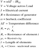
Equation (2) shows the voltage produced by the Seeback effect.
Equation (3) gives us the resistance of the thermoelectric elements depend on the electrical resistivity as well as the length and cross sectional area. The power in a resistor is V2/R the power
produced in a thermoelectric generator depends on
the square of the voltage (Seebeck coefficient and temperature difference) divided by the resistivity. Notice also that the power per area can be arbitrarily adjusted with l (length).
Equation (4) gives the power produced in the thermoelectric generators.
It can be shown that the maximum efficiency of a thermoelectric material depends on two terms. The first is the Carnot efficiency, for all heat engines can not exceed Carnot efficiency. The second is a term that depends on the thermoelectric properties, Seebeck coefficient, electrical resistivity and thermal conductivity. These material properties all appear together and thus form a new material property which we call zT, the Thermoelectric Figure of Merit [9]. For small temperature difference this efficiency is given by:

Notice also that the extensive geometric parameters, length and area have dropped out of this expression for maximum efficiency. In a real generator with large temperature difference other methods and approximations are frequently used to calculate performance [10].
Another material property that becomes important when different materials or large temperature differences are used, is the thermoelectric compatibility factor s. For power generation, the compatibility factor should not change by more than a factor of two from the hot to the cold end of a thermoelectric element.

Equation (5) gives the thermoeletric compatibility factor.
The power supply unit also consists of the use of instrumentation amplifier. AD620 chip provides
IJSER © 2013 http://www.ijser.org
International Journal of Scientific & Engineering Research, Volume 4, Issue 10, October-2013 583
ISSN 2229-5518
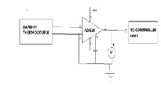
a low-cost and accurate amplification mechanism to amplify the generated thermo-electric emf such that it can be easily measured with a digital multi-meter or data logger. The AD620 chip requires only one external resistor to set gains of 1 to 10,000. Furthermore, the AD620 chip requires lower power (only 1.3 mA maximum supply current), making it a suitable selection for battery-powered or portable applications.
Fig.6 shows the controller unit of the proposed system.
Fig.5 shows the power supply unit.
7 CONTROL UNIT
The control unit consists of the ultra low power microcontroller MSP430G2553 which operates at extreme low power. This microcontroller consists of the ADC unit, ports to interface to a computer system
either through modem or through wireless mediums like bluetooth, zigbee, etc. The controller is programmed through the Code composer Studio version 5, and the timer is used to deliver the current pulses at the specified time with required intensity of current pulses. MSP430 CPU has a 16-bit RISC architecture that is highly transparent to the application.
All operations, other than program-flow instructions, are performed as register operations in conjunction with seven addressing modes for source operand and four addressing modes for destination operand. The CPU is integrated with 16 registers that provide reduced instruction execution time. The register-to register operation execution time is one cycle of the CPU clock. Four of the registers, R0 to R3, are dedicated as program counter, stack pointer, status register, and constant generator, respectively. The remaining registers are general-purpose registers. Peripherals are connected to the CPU using data, address, and control buses, and can be handled with all instructions.The instruction set consists of the original 51 instructions with three formats and seven address modes and additional instructions for the expanded address range. Each instruction can operate on word and byte data.
The microcontroller works in six low power modes. The EMG feedback sensors connected to the patient collects the EMG signals from their muscles of upper limbs or lower limbs, then they are fed to the ADC unit of the microcontroller. The microcontroller has 10 ADC channels that are in built so it avoids the need of external ADC chip. The RX and TX provides the interface for connectivity such that they are used in transmission and receiving data through either wired or wireless interfaces. The self power generation unit is connected to the controller power supply which requires low power.
The Memory unit of microcontroller have EEPROM. Thus it can be used and electronically erased easily. The output digital signals are connected to DAC and they are connected to current source for producing the current pulses at required intensities at negligible time which produces biphasic waveforms. The DC-DC converter is used to regulate the voltage at specified intensity as per required by the patient. The LCD is pre programmed to deliver the readings of the digital signals of EMG.
8 FEEDBACK SYSTEM
The feedback system includes the usage of EMG sensors which extracts the EMG signals from the muscles of the body such that it is fed to the ADC unit of the MSP430 microcontroller. These EMG signals
provide the feedback to the system and provide the stimulation when required.
9 STIMULATOR ELECTRODE
The current source is connected to the patient electrode which is used to provide the functional electrical stimulations at required intensity to patients at negligible time. Mostly stimulator needles are used for providing the stimulations which are mostly intramuscular or intraneural or surface electrodes.
10 SOFTWARE REQUIREMENTS
IJSER © 2013 http://www.ijser.org
International Journal of Scientific & Engineering Research, Volume 4, Issue 10, October-2013 584
ISSN 2229-5518
The software required for this proposed system is Code composer Studio v 5.0 which used for programming the MSP430 microcontroller. The programmer is performed by use of the MSP430
Launchpad that has the USB interface to the PC. While programming the MSP430 microcontroller, the timer is set as per the requirement of the patient based on the parts of the body where the stimulation is applied.
11 GAIT ANALYSIS USING THE PROPOSED SYSTEM
Gait analysis is facilitated by the acquisition of objective data that describes a subject’s movement and a physical examination and relevant medical history [12]. Any movement can be studied but the most common clinical analysis is of walking and movement of arms.Walking involves complex neurological control of limb movements while movement of arms contain the easy control of limb movements. People with walking difficulties often have different ways of coordinating their movements and adapting to their walking limitations. Clinical gait analysis is used to help understand pathology that affects gait. Mostly the dorsal flexors of the foot is applied with FES to regain gait [13].
Pathologies studied by clinical gait analysis include cerebral palsy, spina bifida, talipes, stroke and amputees. The resulting information can assist clinicians [14] in making decisions about the patient’s management.
Research into human movement is greatly enhanced by the use of an objective tool such as movement analysis, allowing repeated assessment under different conditions. It encompasses many areas including fundamental studies of muscle activity and function, as well as more applied areas such as rehabilitation, development of prostheses and ergonomics. Sports and exercise science is another major area with studies of human movement in athletics, golf and other activities.
A variety of equipment is available for analysis of human movement:
• 2D video analysis: high quality video footage of coronal (frontal) and sagittal (side) views is included in clinical gait analysis. Video provides a record of the overall gait style and functional ability.
• 3D computerised analysis: markers are placed on the legs and pelvis and their positions as the subject walks along a walkway are recorded by cameras. In the case of movement of upper limbs, the markers are placed on the joints and the shoulders and recorded by a camera. By computing the 3D position of the markers the movement of the subject can be regenerated. From this the position of the limb segments and the angles at the joints (kinematics) can be calculated. The kinematics for normal
walking are distinctive. The results from subjects with gait disorders can be compared to these to help diagnose the problem and decide a treatment.
• Force measurement: The force applied to the floor during walking is measured using one or more force plates embedded in the floor of the walkway. By combining this with the 3D information, a biomechanical model can be used to find the moments and powers (kinetics) acting at the joints.
Muscle activity and energy cost: electromyography (EMG) equipment can be used to record muscle activity during walking using surface electrodes. Measurements of oxygen consumption or heart rate may be used as a measure of energy consumption. Clinical gait analysis would typically comprise a number of elements: (1) a clinical examination to assess joint movement range, muscle strength and tone and bone alignment; (2) video recording of the patient’s walking style; (3) motion capture using a 3D system of the patient walking with markers attached to the lower body to provide an accurate measure of the movement pattern. During the assessment, emphasis is placed on obtaining good quality representative data, which is later collated in a report to the referring physician. Labs conduct review sessions in which a multidisciplinary team, usually including a consultant orthopaedic surgeon, physiotherapists and clinical scientists, review the patient’s data before the report is finalised. A report containing the gait data, interpretation and recommendations would be compiled and forwarded to the referrer. By this method the differentiation between the normal and the abnormalities in the movement of the limbs, the gait can be easily studied by the clinical doctors, physiotherapists for those who are not patient. The abnormalities can be easily detected by video analysis method and real time 3d visual analysis.
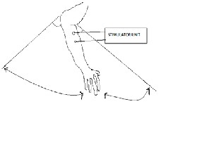
Fig.7 shows the gait analysis of the arms
IJSER © 2013 http://www.ijser.org
International Journal of Scientific & Engineering Research, Volume 4, Issue 10, October-2013 585
ISSN 2229-5518
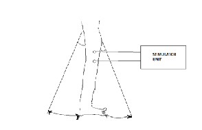
Fig.8 shows the gait analysis of legs
The FES is used in the recovery of the paralysed patients mainly in the arms and limbs. It also recovers the patients from hemiplegia, quadriplegia, paraplegia, and stroke treatment too. Assess the level of disability of upper extremities and lower extremities [15]. The applications of FES in stroke recovery were focused on drop-foot correction, later researchers began to selectively stimulate the muscles for dorsiflexion of the foot as well as other key muscle groups in the affected leg [16]. FES combined with other gait retraining strategies results in improvements in hemiplegic gait, faster rehabilitation process [17] and enhancement of the patients' endurance controlled by the ultra low power microcontoller [18].
11 ADVANTAGES OF THE PROPOSED SYSTEM
The advantages of the proposed system
includes the follows:
• Self power generation
• Used for treatment of stroke recovery.
• Used in neuro rehabilitation in the control of the prosthetic and orthotic devices and increases the speed of movement.
• Low cost device with easy circuit designs.
• Good controlling mechanisms with feedback system.
12 CONCLUSION
The need for the FES is more increasing for the healthcare industries, that not only used for the treatment for the people but also used in the neuro rehabilitation and in gait analysis. The motion of the arms and limbs are differentiated between normal and abnormal conditions. Even FES provides pain relief from the body parts and is suitable for portable
applications.
REFERENCES
[1].Nikola Jorgovanović, Strahinja Došen and Ratko Petrović, “Novel Electronic Stimulator for Functional Electrical Therapy,” Journal of Automatic Control, University of Belgrade, vol.15(supplement), 2005.
[2] R. J. Weber, “Functional neuromuscular stimulation,” in Rehabilitation Medicine: Principles and Practice. Philadelphia, PA: Lippincott, 1993.
[3] R. B. Stein, M. Belanger, G. Wheeler, M. Wieler, D. B. PopoviC, A. Prochazka, and L. Davis, “Assessment of electrical stimulation system for improving locomotion after incomplete spinal cord injury,” Arch. Phys. Med. Rehab., vol. 74, pp. 954-
959, 1993.
[4] K. W. Eric Cheng, Yan Lu, Kai-Yu Tong, A. B. Rad, Daniel H. K. Chow, and Danny Sutanto, Senior Member, IEEE, “Development of a Circuit for Functional Electrical Stimulation,” IEEE Transaction on Neural Systems and Rehabilitation Engg., vol.
12,No. 1, March 2004.
[5] Barry J. Broderick, Paul P. Breen and Gearóid ÓLaighin, “Electronic Stimulators for Surface Neural Prosthesis,” Journal of Automatic Control, University of Belgrade, vol. 18(2):25-33, 2008.
[6] H. Hirayama, T. Kimura, “Theoretical 1nalysis of the Human Heat Production System andits Regulation”, SICE '98. Proceedings of the 37th SICE Annual Conference.
[7] V. Leonov, P. Fiorini, S. Sedky, T. Torfs, C. Van Hoof, “Thermoelectric MEMS generators as a power supply for a body area network”, Proceedings of the
13th Int. Conf. On Solid-State Sensors, Actuators and Microsystems – Transducers 2005 05-06-2005 Seoul (Korea),pp. 291-294.
[8] M. Strasser, R. Aigner, C. Lauterbach, T. F. Sturm, M. Franosch and G. Wachutka, “Micromachined CMOS Thermoelectric Generator As Onchip Power Supply”, Sensors andActuators A, Vol.114, pp.362-
370, 2004.
[9] G. Snyder and E. Toberer, “Complex
Thermoelectric Materials”, Nature materials Vol 7(2), February 2008, pp 105-114.G. Ben Hmida, A. L. Ekuakille, A. Kachouri, H. Ghariani, and A. Trotta,
[10] V. Leonov, unpublished. See also: Z. Wang, V. Leonov, P. Fiorini, C. Van Hoof, “Micromachined thermopiles for energy scavenging on human body”, Int. Conf. On Solid- State Sensors, Actuators and Microsystems TRANSDUCERS 2007. 10-14 June
2007, pp.911-914.
[11] V. Leonov, T. Torfs, P. Fiorini, C. Van Hoof,
”Thermoelectric converters of human warmth for self-
powered wireless sensor nodes”, IEEE Sensors
Journal, pp. 650 – 657, 2007.
[12] Craik RL & Oatis CA, 1995, Gait Analysis, Theory
and Application, Mosby, St. Louis, Missouri,USA. [13]. Liberson, W.T., et al., Functional electrotherapy: stimulation of the peroneal nerve synchronized with the swing phase of the gait of hemiplegic patients. Arch Phys Med Rehabil, 1961. 42: p. 101-5.
[14]. SCIIN, Spinal cord injury: facts and figures at a glance - June 2005. 2005, Spinal Cord Injury Information Network.
[15]. Peckham, P.H., et al., Efficacy of an implanted
neuroprosthesis for restoring hand grasp in tetraplegia: a multicenter study. Arch Phys Med Rehabil, 2001. 82(10): p. 1380-8.
IJSER © 2013 http://www.ijser.org
International Journal of Scientific & Engineering Research, Volume 4, Issue 10, October-2013 586
ISSN 2229-5518
[16]. McClelland, M., et al., Augmentation of the Oswestry Parawalker orthosis by means of surface electrical stimulation: gait analysis of three patients. Paraplegia, 1987. 25: p. 32-38.
[17].. Nene, A. and S. Jennings, Hybrid paraplegic locomotion with the Parawalker using intramuscular stimulation: a single subject study. Paraplegia, 1989.
27: p. 125-132.
[18]. Petrofsky, J. and J. Smith, Physiologic costs of computer-controlled walking in persons with paraplegia using a reciprocating-gait orthosis. Arch Phys Med Rehabil, 1991. 72(11): p. 890-896.
IJSER © 2013 http://www.ijser.org