Inte rnatio nal Jo urnal o f Sc ie ntific & Eng inee ring Re se arc h, Vo lume 3, Issue 1, January -2012 1
ISS N 2229-5518
SAT Implementation in Direct Torque Control For Dynamic Response in Multi Level Inverter Induction Motor DRIVES
ROHITHBALAJI JONNALA
Abs tract— This paper presents the implementation of Direct Torque Control (DTC) w ith Sector Advancement Technique (SAT) algorithm f or the control of a Hybrid Cascaded H-Bridge Mult ilevel Inverter Induction motor Drive. It is usef ul to keep the motor torque and stator f lux and the inverter’s neutral point potential w ithin given hysteresis bounds w hile reducing the average sw itching f requency of the inverter and overall computational time period comparison w ith the standard direct torque control (CDTC). This method also improving overa ll eff iciency w ith Torque and Flux ripple reduction. In add ition, the mu ltilevel inverter can generate a high and f ixed sw itching f requency output volt age w ith f ew er sw itching losses, since only the small pow er cells of the inverter operate at a high sw itching rate. Therefore, a high perf ormance and also eff icient torque and f lux controllers are obtained, enabling a DTC solution f or multilevel-inverter-pow ered motor drives.
Inde x Terms— Direct Torque Control (DTC), Mult i Level Inverter, Induction Motor Drives, Sector Advancement Te chnique (SAT).
—————————— ——————————
1 INTRODUCTION
S
ince its introduction, direct torque control (DTC) has
become a powerful control scheme for the control of
induction motor (IM) drives. The standard DTC
scheme uses hysteresis compa rators for the control of both stator flux magnitude and electromagnetic torque. This control structure ideally keeps both controlled parameters within the hysteresis bands and results in a non constant switching frequency. One of the methods that have been used by one major manufacturer in multilevel inverters is direct torque control (DTC), which is recognized today as a high - performance control strategy for ac drives. Several authors have addressed the problem of improving the behaviour of DTC ac motors, particularly by reducing the torque ripple. However, when the DTC scheme is used in a discrete impl e- mentation, both torque and flux exceed the bands imposed by the hysteresis comparators, due to the fixed sampling frequen- cy. It is possible for the discrete scheme to operate as an ana l- ogy one if the hysteresis bounds are chosen to be sufficiently large. On the contrary, when the width of the bands is compa- rable to the maximum torque and flux variations during one sampling period, the excursions will be rela tively large, partly due to the time delay that is caused by the data processing. Therefore, the sampling period is an important factor deter- mining the control performance and switching frequency.
To improve the performance of control operation, different approaches have been proposed: improving the loo- kup table; varying the hysteresis bandwidth of the torque con- troller; and using flux, torque, and speed observers. Although these approaches are well suitable for the classical two-level inverter, their extension to a greater number of levels is not easy. Throughout this paper, a theoretical background is used to design a simple and practical strategy that is compatible
with hybrid cascaded H-bridge multilevel inverter. It allows
not only controlling the electromagnetic state of the motor
with improved performance (minimization of the torque ri p-
ple) but also reducing flux and current distortion caused by flux position sector change.
To improve the flux waveform, ripple free torque,
dynamics and efficiency of the drive and to enhance th e quali- ty of stator currents in the motor. Sector Advancing Technique (SAT) is employed for reducing the response time of the drive to given torque command.
2 C ASC ADED H-BRIDGE STRUCTURE AND OPER ATION
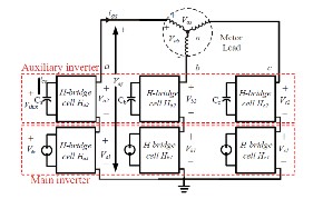
The hybrid cascaded H-bridge inverter is composed of three legs, in each one is a series connection of two H-bridge inverters fed by independent dc sources that are not equal (V1
< 2).Indeed, it may be obtained from batteries, fuel cells. The use of asymmetric input voltages can reduce, or when proper- ly chosen, eliminate redundant output levels, maximizing the number of different levels generated by the inverter. There- fore, this topology can achieve the same output voltage quality with fewer numbers of semiconductors .
———— ——— ——— ——— ———
ROHITHBALAJI JONNALA was with the department of Electrical and Elec- tronics Engineering, G V V Institute of Technology, JNTUK , Bhimavaram,
INDIA, PH-+91-9989262655. E-mail: rohithbalajijonnala@yahoo.com Figure 1: Cas caded H-Bridge Inverter
IJSER © 2012
http :// www.ijser.org
Inte rnatio nal Jo urnal o f Sc ie ntific & Eng inee ring Re se arc h, Vo lume 3, Issue 1, January -2012 2
ISS N 2229-5518
The use of asymmetric input voltages (inverter fed by a set of dc-voltage sources where at least one of them is differ- ent from the other one) can reduce, or when properly chosen, eliminate redundant output levels, maximizing the number of different levels generated by the inverter.
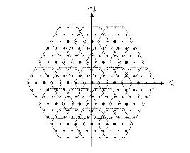
Figure 2: Voltage Vector formation in Multilevel Inverter
Therefore, this topology can achieve the same output vol- tage quality with fewer numbers of semiconductors. The maxi- mum number of redundancies is equal to (3K −2K − 1) and can be obtained when the partial dc voltages are equal to E/ (N − 1). If there is 2K connected cells per multilevel-inverter phase leg, 3K
switching configurations are possible and N is number of levels .
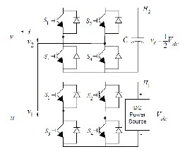
Figure 3 : Basic H-Brid ge Structure
The multilevel-inverter output voltage depends on the partial voltage feeding each partial cell. The possible num- ber of redundant switching states can be reduced if the cells are fed by unequal dc-voltage sources. This also reduces vo- lume and costs and offers inherent low switching losses and high conversion efficiency. When cascading two-level inver- ters like H-bridges [Fig3], the optimal asymmetry is obtained by using voltage sources proportionally scaled to the two- or three-H-bridge power. Particular cell i can generate three l e-
vels (+Vi, 0, −Vi). The total inverter output voltage for a pa r- ticular phase j is defined by
Where νij is the i cell output voltage, m is the number of cells per phase, and (Si1, Si2) is the switching state associated to the i cell. Equation (1) explicitly shows how the output voltage of one cell is defined by one of the four binary combinations of switching state, with ―1‖ and ―0‖ representing the ―ON‖ and ―OFF‖ states of the corresponding switch, respectively. The optimal asymmetry is obtained with dc links scaled in powers of two or three, generating seven or nine different output levels. Nine different output levels can be generated using only two cells (eight switches); while four cells (16 switches) are necessary to achieve the same amount of level with a symmetric-fed inverter.
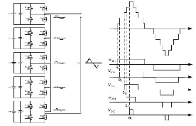
Figure 4: Level based Output representation with Circuit
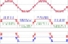
Figure 5: 7 Level output and respective +ve, -ve cycles pulses generated by PWM generator
To implement the DTC of the induction motor fed by a hybrid H-bridge multilevel inverter, one should determine at each sampling period the logic state of the inverter switches as a function of instantaneous values of torque and flux for the selection of the space vector in the α−β frame. That space vol- tage vector are based on level of the inverter for example sev-
IJSER © 2012
http :// www.ijser.org
Inte rnatio nal Jo urnal o f Sc ie ntific & Eng inee ring Re se arc h, Vo lume 3, Issue 1, January -2012 3
ISS N 2229-5518
en level inverter has 343(73) voltage vectors [Fig2].
3 INDUCTION MOTOR DTC
DTC is an alternative method to flux-oriented control. The basic principle is the selection of th e electromagnetic tor- que and stator flux references by choosing the appropriate inverter state. Several advantages may be considered, namely, nearly sinusoidal stator flux and current waveforms, higher robustness regarding motor parameter variations except the stator winding resistance, higher torque dynamics, and easier flux and speed estimator implementation, since coordinate transformation is not required. However, in the standard ver- sion, important torque ripple and high switching losses are obtained due to the use of hysteresis bands and the small number of applicable voltage vectors. Moreover, the converter switching frequency is inherently variable and very depen- dent on the torque and shaft speed. This produces torque harmonics with variable frequencies and acoustic noise with disturbance intensities that are very dependent on these me- chanical variables and particularly grating at low speed. The additional degrees of freedom (space vectors, phase configura- tions, etc.) provided by the multilevel inverter should there- fore be exploited by the control strategy in order to reduce the previously cited drawbacks.
The dynamic T- model of induction machine in the stator ref- erence frame is given in Fig6.
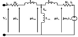
Figure 6: Equivalent circuit for Induction motor
The stator flux is given by

While the rotor flux in the squirrel cage induction motor satisfies the relation
and rotor flux and is called as torque angle. The torque can be controlled by adjusting this angle. The magnitude of stator flux λs, a measure of intensity of magnetic field in the motor is directly dependent on the stator voltage and is given in equa- tion (5). The same stator voltage Vs can also be employed to control θsr there by controlling the torque developed.
It is observed that the derivative of stator flux reacts instantly to changes in the stator voltage, the respective two space vectors are separated in the circuit by the stator resis- tance Rs only. However, the vector derivative of rotor flux
‗P*λr‘ is separated from that of stator flux by stator and rotor leakage inductances. Therefore the reaction of rotor flux vector to stator voltage is somewhat sluggish in comparison with that of stator flux vector.
The basic principle is the selection of two stator cu r- rents ia and ib are measured and space vectors Vs and Is of stator voltage and current are determined in the voltage and current synthesizer.
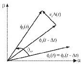
Figure 7: Effect of Voltage Vector on Stator Flux and Torque

Torque and Flux Estimation:

The torque developed ‗TM‘ can be expressed in several forms, one
such form is

The torque developed by in an induction motor can be written as


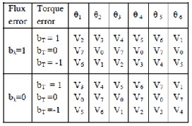
Based on Vs and Is, the stator flux vector of the stator flux is compared with the reference value and is compared with the reference torque in the torque control loop. The flux and tor- que errors bλ and bT are applied to respective hysteresis con- trollers. The flux controller output signal can assume the va l- ues 0 and 1 and that of torque controller can assume the va l- ues of -1, 0, and 1. Selection of inverter state is based on values of -1, 0 and 1.

Here θsr denotes the angle between the stator flux
IJSER © 2012
http :// www.ijser.org
Inte rnatio nal Jo urnal o f Sc ie ntific & Eng inee ring Re se arc h, Vo lume 3, Issue 1, January -2012 4
ISS N 2229-5518
Based on these effects on drive, the requirements are controlled on several computation samples.
The main purpose of the DTC is to select the best vec- tor of voltage, which restrict the flux and torque errors within respective flux and torque hysteresis bands. Mathematical model of induction motor are needed for estimate flux and torque.
Figure 8: Selection of Voltage State based on Flux and Torque Error
Selection of inverter state is based on sector, errors in tor- que and flux. The electromagnetic torque and stator flux references by choosing the appropriate inverter state.
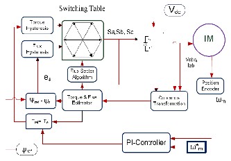
Figure 11: Basic DTC Block Diagram
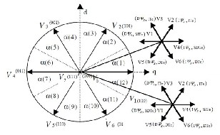
Figure 9: Possible Voltage changes with Sector indication
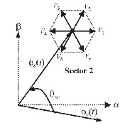
Figure 10: Effect of stator voltage vector on Torque and Flux
The idea of DTC was to control the stator flux linkage and the torque directly, not via controlling the stator current. This was done by controlling the power switches directly u s- ing the output of hysteresis comparators for the torque & the modules of the stator flux linkage and selecting an appropriate voltage from a predefined switching table. Fig.8 shows the direct torque control scheme for induction motor drive. The main building blocks are speed PI controller, torque, flux and field angle calculator, torque and flux hysteresis comparators, optimum voltage vector selection table and inverter. The DTC control scheme was done by controlling the power switches directly by switching the voltage vector so as to keep the flux and torque within the specified limits of torque and flux hys- teresis comparators. Here rotor speed is compared with the reference speed and given to speed controller which has PI controller gives reference torque and a field weakening c on- troller which is for above rated speed operations. The refer- ence torque and flux is compared with calculated torque and flux. The error signals are given to the hysteresis controllers and these signals along with sector value are used to give op- timum voltage signals to the inverter based on the designed optimum switching table. Here the parameters required for the DTC control scheme are stator currents and the armature resistance of the Induction motor.
IJSER © 2012
http :// www.ijser.org
Inte rnatio nal Jo urnal o f Sc ie ntific & Eng inee ring Re se arc h, Vo lume 3, Issue 1, January -2012 5
ISS N 2229-5518
4 IMPLEMENTATION OF SECTOR AD VANCING TECHNIQUE
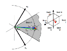
In a DTC, a vector of inverter voltage used in one sector of the vector plane to decrease the stator flux is employed in next sector when the flux is to be increased. With such a control the trajectory of stator flux control vector forms a piecewise linear approximation of a circle.
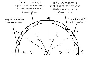
Figure 12: Selection of Voltage Vector with DTC
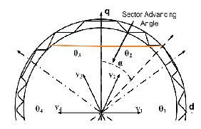
Figure 13: DTC with SAT Implementation
In the proposed Sector Advancing Technique, the line separating the two sectors is shifted back by an angle α ra- dians. Due to this there is an advancement of a sector by an angle α at that boundary region and the inverter applies vec- tor states of next sector into the present sector. As the linear speed of the stator flux vector along its trajectory is constant and equals to the dc supply voltage of the inverter, the voltage vector swiftly moves to next sector in a shorter time than if it travelled along the regular trajectory. The acceleration of sta- tor flux vector results in a rapid increase of the torque, because that vector quickly moves away from the rotor flux vector. The greater the sector shift α , the greater the torque increase. Ad- vancement allows 0-60 deg.
5 SIMULATIO N RESU LTS
To validate the proposed sector a dvancement tech- nique, simulations have been carried out by using MAT- LAB/SIMULINK, with the following machine parameters. Rated power: 1.5kW, 4 pole, Rs=8.49Ω, Rr=7.65Ω, Ls=0.5253H, Lr=0.5253H,Lm=0.5015H, J=0.02 kg-m2 the reference torque is taken as 20 N-m and reference flux as 1
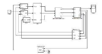
Figure 14: Proposed circuit for SATDTC with MLI IM Drives
The simulation model is given in Fig. 14. The locus of flux in Conventional DTC(CDTC) and with 300 angle a d- vancement in sector 2 of SAT in DTC (SATDTC). It is observed that the acceleration time to reach reference torque of 20N -m first time is 10.2ms in CDTC and it is 14.25ms in SATDTC which is slightly more than that of CDTC. However the time taken by DTC to reach a load torque of 5N-m is 0.45 s where as that in SATDTC it is 0.422 s (approximately 6.22% improve- ment) which proves that there is an improvement in the dy- namic response with sector angle advancement. The time to reach final speed in CDTC is 0.5s and in proposed scheme it is
0.45s. The stator currents are shown in Fig. 15 and Fig. 16.
Studies have been made on response time, torque ripple, speed, flux ripple, steady currents by varying the sector angle advancement from 00 to 600 .
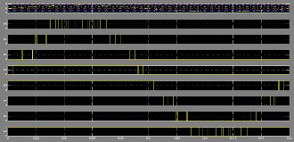
Figure 15: Pulses generated by PWM Technique
IJSER © 2012
http :// www.ijser.org
Inte rnatio nal Jo urnal o f Sc ie ntific & Eng inee ring Re se arc h, Vo lume 3, Issue 1, January -2012 6
ISS N 2229-5518
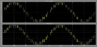
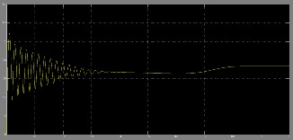
Figure 16: Stator Voltage and Current waveforms 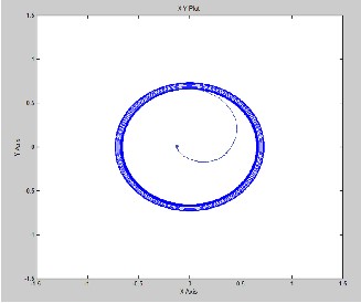
Figure 20: Locus of Flux trajectory with SAT DTC
Figure17: Stator frame Flux with SATDTC
Figure18: Torque variations with SATDTC
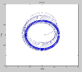
Figure 19: Locus of Flux trajectory without SAT DTC
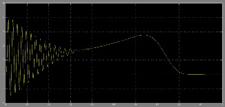
They appear completely sinusoidal, since the low- pass nature of the load has filtered the high frequency content of the applied voltage. The stator flux, shown in Fig. 17, is measured with constant amplitude imposed by the flux con- troller. This result confirms the good dynamic performance of the drive. The most important experimental result is that the torque ripple, as shown in Fig. 18, has been almost eliminated in comparison to a two-level traditional DTC.
6 CONCLUSION
This paper has dealt with a hybrid cascaded H-bridge multilevel motor drive DTC control scheme with SAT that has big potential for EVs or HEVs. The main achievements of the proposed control method are significant reduction in the torque ripple, sinusoidal output voltages and currents, lower switching losses, and a high-performance torque and flux regulation. Sector Advancement Technique ( SAT) has been proposed to improve the dynamic response of a Direct Torque Controlled Induction Motor. Simulation studies show that the improvement in dyna m- ic response is 6.22% in SATDTC as compared to CDTC for the selected induction motor. The hybrid multilevel inverter enables a DTC solution for high-power motor drives, not only due to the higher voltage capability provided by multilevel inverters but also mainly due to the reduced switching losses and the im- proved output voltage quality, which provides a sinusoidal cu r- rent without an output filter.
IJSER © 2012
http :// www.ijser.org
Inte rnatio nal Jo urnal o f Sc ie ntific & Eng inee ring Re se arc h, Vo lume 3, Issue 1, January -2012 7
ISS N 2229-5518
REFERENCES
[1] Georgios Papafotiou, Jonas Kley, Kostas G. Papadopoulos, Pat rick Bohren, and Manfred Morari, ―Model Predictive Direct Torque Con- trol—Part II: Implementation and Experimental Evaluation‖ IEEE TRANSACTIONS ON INDUSTRIAL ELECTRONICS, VOL. 56, NO.
6, JUNE 2009
[2] Jef Beerten, Jan Verveckken, and Johan Driesen, ―Predictive Direct Torque Control for Flux and Torque Ripple Reduction‖ IEEE TRANSACTIONS ON INDUSTRIAL ELECTRONICS, VOL. 57, NO.
1, JANUARY 2010
[3] Narasimham PVRL, Sarma AVRS, Vargil kumar E, ―A Sector A d- vanced Technique to Improve Dynamic Response of a Direct Torque Controlled Induction Motor‖ 2010 IEEE International Conference on Power and Energy (PECon2010), Nov 29 - Dec 1, 2010, Kuala Lum- pur, Malaysia
[4] Farid Khoucha, Soumia Mouna Lagoun, Khoudir Marouani, Abdela- ziz Kheloui, and Mohamed El Hachemi Benbouzid, ―Hybrid Ca s- caded H-Bridge Multilevel-Inverter Induction-Motor-Drive Direct Torque Control for Automotive Applications‖ IEEE TRANSA C- TIONS ON INDUSTRIAL ELECTRONICS, VOL. 57, NO. 3, MARCH
2010
[5] KUTASI Dénes Nimród, ―MODEL-BASED PREDICTIVE CONTROL OF POWER ELECTRONIC CONVERTERS ‖ SUMMARY OF PHD THESIS UNIVERSITATEA TEHNICÄ
[6] Y.V.Siva Reddy, M.Vijayakumar and T. Brahmananda Reddy, ―D i- rect Torque Control of Induction Motor Using Sophisticated Lookup Tables Based on Neural Networks‖ AIML Journal, Volume (7), Issue (1), June, 2007
[7] Libo Zheng, John E. Fletcher, Barry W. Williams, and Xiangning He,
―A Novel Direct Torque Control Scheme for a Sensorless Five-Phase Induction Motor Drive‖ IEEE TRANSACTIONS ON INDUSTRIAL ELECTRONICS, VOL. 58, NO. 2, FEBRUARY 2011
[8] I.Takahashi and T. Noguchi , ―A new quick response and high eff i-
ciency control strategy of an induction motor ―, IEEE Trans. Indus.
Appl. Vol.22, no.5pp 820 -827 (1986).
[9] M. Depenbrock ,‖Direct Self Control (DSC) of inverter fed induction machine‖, IEEE Trans. Power Electronics , Vol. no. 3 , pp 420-
429(1988).
[10] I. Tahahashi and Y. Ohmori , ―High –Performance direct torque con-
trol of induction motor ‗ IEEE Tran. Indus. Appl. Vol. 25, pp257-
264(1989)
[11] G.R. Selmon ― Modelling of induction machines for electric Drives‖,
IEEE Tran. Ind. Appl. Vol 25 No.6 pp 1126-1130 ( 1989).
[12] I.Takahashi and T. Nouguchi, ―Take a look back upon the past dec- ade of direct torque control‖, Proc.IEEE – IECON 97 ,23rd Interna- tional Conference, Vol2, pp546-551,1997.
[13] L. G. Franquelo, J. Rodriguez, J. I. Leon, S. Kouro, R. Portillo, and M.
A. M. Prats, ―The age of multilevel converters arrives,‖ IEEE Ind.
Electron. Mag., vol. 2, no. 2, pp. 28–39, Jun. 2008.
[14] J. Rodriguez, J. S. Lai, and F. Z. Zeng, ―Multilevel inverters: A survey of topologies, controls and applications,‖ IEEE Trans. Ind. Electron., vol. 49, no. 4, pp. 724–738, Aug. 2002.
[15] A. Das, K. Sivakumar, R. Ramchand, C. Patel, and K. Gopakumar, ―A
combination of hexagonal and 12 -sided polygonal voltage space vec- tor PWM control for IM drives using cascaded two-level inverters,‖
IEEE Trans. Ind. Electron., vol. 56, no. 5, pp. 1657–1664, May 2009.
[16] X. Yuan and I. Barbi, ―Fundamentals of a new diode clamping mult i-
level inverter,‖ IEEE Trans. Power Electron., vol. 15, no. 4, pp. 711–
718, Jul. 2000.
[17] J. Huang and K. A. Corzine, ―Extended operation of flying capac itor
multilevel inverters,‖ IEEE Trans. Power Electron., vol. 21, no. 1, pp.
140–147, Jan. 2006.
[18] M. F. Escalante, J. C. Vannier, and A. Arzande, ―Flying capacitor multilevel inverters and DTC motor drive applications,‖ IEEE Trans. Ind. Electron., vol. 49, no. 4, pp. 809–815, Aug. 2002.
[19] T. Ishida, K. Matsuse, T. Miyamoto, K. Sasagawa, and L. Huang,
―Fundamental characteristics of five-level double converters with a d- justable DC voltages for induction motor drives,‖ IEEE Trans. Ind. Electron., vol. 49, no. 4, pp. 775–782, Aug. 2002.
IJSER © 2012
http :// www.ijser.org