
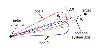
The amplitude-comparison mono-pulse system should have two equal antennas with overlapping patterns and their main beam directions squinted at certain angle θs (Fig. 1).
International Journal of Scientific & Engineering Research, Volume 6, Issue 4, April-2015 1614
ISSN 2229-5518
S-Curve Analysis of a Monopulse RADAR Receiver to find its Tracking Zone
Vishal Das, Debasish Bhaskar, Rabindranath Bera
For today’s vehicular driver assistance, this digital beam forming based adaptive tracking system is highly efficient and approaching towards cost effective commercial utilization.
—————————— ——————————
There are different types of radars, such as search radars, tracking radars, etc. Each of these radars has a specific application. The main task of search radars is to detect targets at long distances and track radars main responsibility is to follow and track the vehicle (target). The main components of the radar-range search radars and precision tracking radars and tracking of important issues is vital. The signal amplitude fluctuations Monopulse system has no effect, but usually three channel receiver for equipment needs. Monopulse radar is a type of conical scanning radar which sends the information in the radar signal that prevents problems caused by rapid changes in the signal strength. The Monopulse also makes jamming more difficult.
In this paper, the Basics of Monopulse RADAR has been illustrated under Section-II. The Analysis of Monopulse RADAR and Mathematical description has been discussed in Section-III. The working simulation model and its Block Diagram have been illustrated in Section-IV. The final outcomes of the model have been framed under Section-V. The Conclusion of the designed S- Curve Analysis of a Monopulse RADAR Receiver has been highlighted under Section-VI.
The mono-pulse radar system is mainly used for target angle
————————————————
• Vishal Das, Electronics & Communication Engineering,Sikkim Manipal Institute of Technolog, Sikkim, India, PH- 8895658126, E-mail: vishal2009das@gmail.com
• Debasish Bhaskar, Electronics & Communication Engineering, Sikkim Manipal Institute of Technology, Sikkim, India, PH- 9831064181, E-mail: debasishbhaskar@gmail.com
• Rabindranath Bera, Electronics & Communication Engineering, Sikkim
Manipal Institute of Technology, Sikkim, India, PH-9475513358, E-mail:
measurement and tracking. The information on the target angular
position is determined by comparison of signals received in two or more simultaneous beams. The term "mono-pulse" comes from
the ability of this system to extract the angular position from only one pulse. However, in practice the angular position of the target is obtained from multiple pulses in order to improve target detection probability and further improve angle measurement accuracy.
The main advantage of a monopulse system in comparison to standard angle measurement methods is that it is not affected by amplitude fluctuations of the target echo because the angle information is acquired by comparing signals received by sev- eral simultaneous beams and produced by a single echo pulse. If the echo amplitude changes, it changes in the same way in all receiver channels.
There are three main monopulse techniques for angle sensing. These techniques are: amplitude-comparison, phase- comparison and the combination of the amplitude and phase comparison [1], [2]. The applied monopulse technique deter- mines the nature of information in the received signal prior to any processing. This means that the choice of a certain Monopulse technique will determine the construction of the radar antenna system.
Angle measurement in a mono-pulse radar system is per- formed by an angle discriminator. If the angle discriminator is non-coherent and the angle-sensing response is produced only by amplitude relations, it is called amplitude discriminator. Angle discriminators responding only to phase relations are called phase angle discriminators, while angle discriminators responding to both amplitude and phase relations are called sum-and-difference angle discriminators. The type of angle discriminator determines the nature of the processing used to extract the angle information from the received signals.
Any kind of angle-sensing can be combined with any type of angle discriminator. In this paper, a model of an phase- comparison mono-pulse system with sum-and difference an- gle discriminator is described.
IJSER © 2015 http://www.ijser.org
International Journal of Scientific & Engineering Research, Volume 6, Issue 4, April-2015 1615
ISSN 2229-5518
The amplitude-comparison mono-pulse system should have two equal antennas with overlapping patterns and their main beam directions squinted at certain angle θs (Fig. 1).
Fig. 1 Antenna Pattern for sum & Difference Monopulse System.
Two resulting patterns (sum and difference) are obtained by adding and subtracting the signals from the two antennas. Only the sum pattern is used in transmission, while both pat- terns are used in reception. [4]
A Monopulse radar as a tracking radar is used in Monopulse tracking. In Monopulse system, the angular error is determined that it is used to measuring of angu- lar coordinates.
As compared with other radar methods using continuous signals or several sequentially received pulse signals, the Monopulse method offers the advantage of higher measure- ment accuracy (reduction of errors to tenths of an angular mi- nute), because Monopulse radar is not sensitive to fluctuations in the amplitude of the received signals. However, practical operation of Monopulse radar requires a more complicated design of the receiving circuit in the radar station because of the necessity of using several receiving channels. Because of this feature, Monopulse radar is also called multichannel ra- dar.
In the Monopulse technique, 4 different off-axis beams are used simultaneously:
Using special combiners, 2 channels are generated from the
above beams: elevation delta = (A + B) - (C + D), sum = A + B
+ C +D.
The sum channels are used for the transmission and, on
receive, for the range tracking. The delta channels, referenced
in amplitude and phase to the sum channel, provide the angu-
lar errors. [3]
Fig. 2 Monopulse Radar
Monopulse radars are similar in general construction to conical scanning systems, but add one more feature [1]. Instead of broadcasting the signal out of the antenna "as is", they split the beam into parts and then send the two signals out of the antenna in slightly different directions. When the reflected signals are received they are amplified separately and compared with each other, indicating which direction has a stronger return, and thus the general direction of the target relative to the bore-sight. Since this comparison is carried out during one pulse, which is typically a few microseconds, changes in target position or heading will have no effect on the comparison [2].
When radio-frequency energy transmitted from a fixed point continuously strikes an object that is either moving toward or away from the source of the energy, the frequency
of the reflected energy is changed. This shift in frequency is known as the Doppler Effect. The difference in frequency be- tween the transmitted and reflected energy indicates both the presence and the speed of a moving target [3].
A common example of the Doppler Effect in action is the changing pitch of the whistle of an approaching train. The whistle appears to change pitch from a high tone, as the train approaches, to a lower tone as it moves away from the observer. As the train approaches, an apparent increase in frequency (an increase in pitch) is heard; as the train moves away, an apparent decrease in frequency (a decrease in pitch) is heard. This pitch variation is known as the Doppler Effect.
If an object is moving, its velocity, relative to the radar, can be detected by comparing with the transmitter frequency with
the echo frequency (which differs because of the Doppler shift). The difference or beat frequency, sometimes called the Doppler frequency (fd), is related to object velocity.
The separation of the background and the radar contact is based on the Doppler frequency that is caused by the reflection of the signal from a moving object. Disadvantages of the Doppler system are that it does not determine the range of the object, nor is it able to differentiate between objects when they lie in the same direction and are traveling at the same speed. Moreover, it does not “see” stationary or slow-moving objects, which a pulse radar system can detect. To track an
IJSER © 2015 http://www.ijser.org
International Journal of Scientific & Engineering Research, Volume 6, Issue 4, April-2015 1616
ISSN 2229-5518
object with CW Doppler, you must determine the radar range. Since the Doppler frequency is not directly related to range, another method is needed to determine object range. By using two separate transmitters that operate at two different frequencies (f1 and f2), you can determine range by measuring the relative phase difference between the two Doppler fre- quencies. In such a system, a mixer is used to combine the two transmitted frequencies and to separate the two received fre- quencies. This permits the use of one transmitting and receiv- ing antenna. Instead of using two transmitter frequencies, you can find the range by sweeping the transmitter frequen- cy uniformly in time to cover the frequency range from f1 to f2. The beat, or difference, frequency between the transmitted and received signals is then a function of range. In this type of radar, the velocity as well as range is measured.
Radar_MatchedSrc this model is used to generate the fre- quency domain matched output for a given waveform.
Radar_PhaseShift this model is used to add phase shift from the far electric field observation point to digital array antenna. Both rectangle array of equally spaced elements and user defined phase shift are supported. X(t) is the input signal, yi(t) is the ith output signal, Ai is the ith phase to be shifted, then
![]()
Radar Detector This model is used for video signal detec- tion.

Fig. 3 Block Diagram of Monopulse Radar
The above block diagram includes
LFM waveform generator which will generate Linear Fre-
quency Modulation.
Radar_Rx_DBS_2D this model is used as a beam-former whose response is steered to the direction determined by theta and phi. [5]
Radar_PC (Pulse Compression) this model is used for pulse compression (PC) in pulse radar.
The block diagram shows in Fig. 2, how the monopulse is helping for target detection in the sum channel and error in the difference channel. In the transmitter part a LFM source is being used which act as a waveform generator it is passed through a sampler where the sample is set to as 10e6 Hz. The baseband signal is being converter to RF by using a converter with centre frequency at 1GHz. While the target is being de- tected, this has a velocity of 30 m/s and at a distance of 100 m. At receiver end it is collected by RADAR_PhaseShift which add phase shift from the far electric field observation point to digital array antenna. The output is given to RA- DAR_MultiCH_Rx which act as behaviour simulation model of multi-channel receiver from RF to baseband. The model input is a timed input which is used to represent analog/RF circuit digital implementation that involves the notion of time in its behaviour. As we can see the input is taken from the Ra- dar_MultiCH_Rx to both the channels which have a Ra- dar_Rx_DBS which will helping me as a beam-former whose response is steered to the direction determined by theta. Out- put from the Radar_Rx_DBS is given to the Pulse Compres- sion (PC) and another input is given from the Ra- dar_MatchedSrc which is use to generate the frequency do- main matched output for a given waveform. The output of the PC will be an Impulse which is given to the Radar_Detector. Both this channel is passed through an Adder and a Differen- tiator, Adder output is shown in the sink where we can realize target is being detected shown in Fig. 4. At the differentiator output if the target is not being aliened then we can get error values shown in Fig. 5.
In Fig. 6 it is realized both the Main Beam and S-curve, as the antenna element is 16 so this antenna pattern is formed which can be utilize for the detection of “Large RCS” (ex- bus, truck etc.) because of the broader beam of the main lobe and the S-curve, and the analysis part is given below at which an- gle the tracking will be ok. Fig. 7 shows the beam pattern of 32 antenna elements for which can be utilize for “Medium RCS” (ex- cars etc.) detection as the beam become narrower as the
IJSER © 2015 http://www.ijser.org
International Journal of Scientific & Engineering Research, Volume 6, Issue 4, April-2015 1617
ISSN 2229-5518

RCS is being reduced. In Fig. 8 shows beam pattern of 64 an- tenna element for “Small RCS” (ex- Motor bikes etc.) because the beam become narrower, and there analysis. As the target RCS gets reduced, the tracking zone of the receiver should be also made to be adaptive in accordance with the target size and dimension.
Fig. 6 Spacing vs. Delta Curve at 16*1 Element
Analysis of the curve Fig. 6:-
Fig. 4 Target is being detected at Sum Output

Fig. 5 Error is being generated at Difference Output
IJSER © 2015 http://www.ijser.org
International Journal of Scientific & Engineering Research, Volume 6, Issue 4, April-2015 1618
ISSN 2229-5518
19. | 10 | 2.88912 | 0.00266875 | Tracking is Okay |
20. | 12 | 1.45893 | 0.00262972 | Tracking is Okay |
21. | 14 | 0.201634 | 0.00236524 | Tracking is Okay |
22. | 16 | 0.776441 | -0.00187373 | Tracking is Failure |
23. | 18 | 1.41123 | -0.00121844 | Tracking is Failure |
24. | 20 | 1.68613 | -0.00044047 | Tracking is Failure |
25. | 22 | 1.63023 | 0.000397602 | Tracking is Failure |
26. | 24 | 1.31043 | 0.00122889 | Tracking is Failure |
27. | 26 | 0.818879 | 0.00198755 | Tracking is Failure |

Fig. 7 Spacing vs. Delta Curve at 32*1 Element
Analysis of the curve Fig. 7:-
9. | -2 | 6.79183 | 0.00132815 | Tracking is Okay |
10. | -1 | 7.5014 | 0.00070708 | Tracking is Okay |
11. | 0 | 7.74727 | 0 | Tracking is Okay |
12. | 1 | 7.5014 | -0.00070708 | Tracking is Okay |
13. | 2 | 6.79183 | -0.00132815 | Tracking is Okay |
14. | 3 | 5.6988 | -0.00178777 | Tracking is Okay |
15. | 4 | 4.34391 | -0.00203032 | Tracking is Okay |
16. | 5 | 2.87382 | -0.00202669 | Tracking is Okay |
17. | 6 | 1.44088 | -0.0017777 | Tracking is Okay |
18. | 7 | 0.183594 | -0.00131636 | Tracking is Okay |
19. | 8 | 0.790409 | 0.000687034 | Tracking is Failure |
20. | 9 | 1.41629 | -2.34453e-005 | Tracking is Failure |

Fig. 8 Spacing vs. Delta Curve at 64*1 Element
Analysis of the curve Fig. 8:-
IJSER © 2015 http://www.ijser.org
International Journal of Scientific & Engineering Research, Volume 6, Issue 4, April-2015 1619
ISSN 2229-5518
for Student Laboratory” Vol (2), Issue (5), May, 2012.
[2] SKOLNIK, M. I. Introduction to Radar Systems, 3rd ed. New York: McGraw-Hill, 2001.
[3] Nahid Osanloo, Tahmineh Niroomand, Ayaz Ghorbani,” Design and Simulation of Monopulse Radar Receiver with Continuous Wave”, International Conference on Microelectronics, Communication and Renewable Energy (ICMiCR) 2013.
[4] A. J. Rainal, “Monopulse Radars Excited by Gaussian Signals”, IEEE Transaction on Aerospace and Electronic sys, 1996.
[5] Mark Richards, “Fundamentals of Radar Signal Processing”, Mcgraw-Hill, New York, 2005.
The design and simulation of Monopulse RADAR receiver and analysis of the S-curve is presented in this paper. This shows how the tracking zone of an S-Curve in Monopulse RADAR receiver depends upon the no. of antenna elements at transmitter phased array and receiver phased array. As the target RCS gets reduced, the tracking zone of the receiver should be also made to be adaptive in accordance with the target size and dimension. This is managed by the tracking length reduction in S-Curve as shown in Fig.-6, 7 and 8.
Further this may be used for ADAS for Tracking the next vehicle.
[1] Davor BONEFAČIĆ, Julijana JANČULA, Ninoslav MAJUREC,
“Model of a Monopulse Radar Tracking System
IJSER © 2015 http://www.ijser.org