and the ant is relayed by each intermediate node until
it reaches the destination [5].
International Journal of Scientific & Engineering Research Volume 2, Issue 9, September-2011 1
ISSN 2229-5518
Route Failure Management Technique for Ant
Based Routing in MANET
S.B.Wankhade, M.S.Ali
Abstract— In this paper we describe route failure management technique for ant based routing in Mobile Ad Hoc Network (MANET), inspired by Ant colony Optimization and enhanced by Fuzzy logic technique as failure management. In Ant based route discovery, the transmission delay of each link, processing delay at each node, the available bandwidth capacity of each link, and the number of hops visited are collected by the ant agents to estimate the path preference probability. Then the route with higher preference probability is established. For failure management, the node mobility and the link disconnection are predicted using the fuzzy logic and based on this predicted results, route or node failure is identified. Then an alternate path can be established. By simulation results, we show that the routing protocol attains good packet delivery ratio with less packet drop and delay.
Index Terms—ACO, Ant based routing, Fuzzy logic, MANET, Quality of service (QoS)
—————————— ——————————
MANET is a collection of mobile nodes using as transmission medium radio waves, able to communicate with each other using multihops links without the need of any infrastructure. Any mobile node communicates directly using the radio waves with nodes in its transmission range, and uses intermediate nodes to communicate with other nodes which are out of its transmission range.
In an ad hoc network, a routing protocol is required for
transmission of packets through number of nodes.
There is lot of routing protocols proposed in the
literature for ad hoc networks. Discovering a path for packet delivery and delivering the packets to the
correct destination are the functions performed by these protocols. Reliability can be increased if the routing protocol for MANET is distributed in a particular manner.
Proactive routing protocols: on exchanging topological information among the network nodes, the proactive protocols continuously learn the topology of the network.
Reactive routing protocols: Query-reply dialog are the basis of the reactive routing protocols and it establishes routes to the destination only when there is a need.
Hybrid routing protocols: A combination of reactive or proactive feature will give a better
solution when compared to a particular routing protocol [1].
Combinatorial optimization problems such as routing can be solved using ant colony optimization (ACO) in computer networks. Observing the optimization of food gathering by the ants is the basic idea of this optimization. The foraging behavior of real ants has been implemented by ACO. Initially, the ants walk randomly when multiple paths are available from nest to food. A chemical substance called pheromone is laid by the ants while traveling towards food and also during the return trip. This serves as the route mark. The path which has a higher pheromone concentration is selected by the new ants and that path is reinforced. A rapid solution can be obtained by this autocatalytic effect [2].
Forward ants (FANTs) and backward ants (BANTs) are used for creating new routes. A pheromone track is established to the source node by a FANT and to the destination node by a BANT. A small packet with a unique sequence number is known as the FANT. Depending upon the sequence number and the source address of the FANT, the duplicate packets can be distinguished by the nodes [3].
S.B.Wankhade is working towards the Ph.D. degree in ComputerEngineeing from Sant Gadge Baba Amravati University, Amravati, India. E-mail: sunilwankhade9@yahoo.com
Dr. M.S. Ali is working as Principal with PRM College of Engineering and Management, Badnera -Amravati, India. Email:softalis@hotmail.com
IJSER © 2011
h ttp :/ / www. i jser.or g
International Journal of Scientific & Engineering Research Volume 2, Issue 9, September-2011 2
ISSN 2229-5518
The route from source node to destination node changes in the MANET since it consists of mobile nodes. Detection of dynamic topology, generation of path between nodes and handling route failures are performed by the routing algorithm. It has three phases.
Route discovery phase – All feasible paths from source node to destination node are found in this phase.
Route maintenance phase – The path between the nodes are strengthened in this phase.
Route failure handling – Alternate paths are generated if any node along the source to destination fails or moves away from the network
The rest of the paper is organized as follows. In Section
2 we describe the previous work related to Ant routing protocols in MANET. Section 3 describes the route failure management technique. Section 4 present results of a simulation testbed on NS2. Finally in Section 5 conclusion is drawn.
A hybrid multi-path algorithm called AntHocNet, sets up paths in the form of pheromone tables indicating their respective quality. Depending upon the pheromone tables, the data packets are routed randomly over the different paths after the route setup [4].
ARA is a reactive ACO routing algorithm for mobile
ad hoc networks. Route discovery and route
maintenance are the two phases of ARA. The sender broadcasts a forward ant in the route discovery phase
The route discovery phase begins when a data has to be transmitted from the source node to destination node with QoS requirements. Transfer of data takes place after estimation of the route.
Every node in the network broadcasts an Hello ant (HANT) for each second. A neighbor will reply an Hello acknowledgement (HACK) upon receiving an HANT. The time difference between the sending HANT and receiving HACK is estimated as the delay between two nodes.
The sequence number, the source address, the next hop and the pheromone value in the routing table are the basis of distinguishing duplicate packets from the nodes. The ants having a unique sequence number are considered as the Duplicate ants and are removed from the table. On receiving the backward ANT (BANT) from the destination node, the source node establishes path and data packets are transmitted.
A reactive forward ANT (FANT) is broadcasted by the source node when a communication session is started with a specific destination D in the absence of routing table in the intermediate nodes. The information about the next hop to reach the destination is contained in the routing table and the probability for finding which hop is chosen by the ant to reach its destination is given by
i
(T nd )
and the ant is relayed by each intermediate node until
it reaches the destination [5].![]()
Pnd
, 1
i j
HOPNET is hybrid ant colony optimization routing algorithm. The main aim of this hybrid approach is to Improving scalability for ant algorithms. This acts as a zonal system and the network divides in zone and a node may be in multiple routing zones. Each node maintains a table for his zone and it contains the pheromone value for each neighbor node corresponding to all destinations [6].
Adaptive fuzzy ant-based routing (AFAR) algorithm
which combined ACO with the capabilities of the fuzzy logic technique to solve the communication network routing problem. It handles an increased traffic load as well as decreased transmission delay by utilizing network resources more efficiently [Mirabedini et al., 2008].
A Novel method called FuzzyAntnet showed a scalable
and robust mechanism with the ability to reach a
stable behavior even in changing network environment [8]. However it has been investigated only for fixed topology networks.
jN d (T id )
i
Where, N d is the set of neighbors of i over which a
path to d is known.![]() is a parameter that controls the exploratory behavior of the ants.
is a parameter that controls the exploratory behavior of the ants.
Large number of duplicate copies appears in one node due to broadcasting of packets and so only one copy is been selected by considering number of hops and travel time and discarding the other packets. The generation number serves as the basis for discarding the copy of the ant.
The information of the source address, destination address, generation number, trip time, list of visited nodes, the number of nodes visited and a flag for reactive backward ant generation at the intermediate node are included in the reactive forward ant. The same generation ants are the ants that have the same source address, destination address and the generation numbers.
Initially only one path is set up and during the course of the communication session more number of paths
IJSER © 2011
h ttp :/ / www. i jser.or g
International Journal of Scientific & Engineering Research Volume 2, Issue 9, September-2011 3
ISSN 2229-5518
are added with the help of proactive path maintenance mechanism.
The list of nodes visited is maintained by the each
FANT and it gets converted into BANT when the ant
nd
reaches its destination. The entry T i gets updated in
the pheromone table when the backward ant retraces
its path back to sources S.
nd
The pheromone value T i is the running average of
the inverse of the cost, in terms of both estimated time
i
and number of hops to travel to D through n. If ^ is
T d
the traveling time estimated by the ant and h is the number of hops then d is used to update the running average
continuously available from time t0 to t0+Tp
Then the link disconnectivity L(Td) is defined as
L(T d) 1 / L(T p)
Where, the calculation of L (Tp) can be divided into two parts: the link availability when the velocities of the two nodes keep unchanged between t0 and t0+Tp, L1 (Tp), and the one for the other cases, L2 (Tp). That is,
L (T p) L1(T p) L2 (T p)
Calculation of L1 (Tp) is quite easy. L1(Tp) is the probability that the period from To onwards for the two nodes are longer than Tp. Since the movements of the two nodes are unchanged, Tp is the accurate prediction and it serves as the longer one. The movement of the nodes are autonomous and it has
„memoryless‟ exponential distribution. L1(Tp) is given by
i
1
^ hT hop
L1(T p) [1 - E (T p)] 2
-2Tp

d ( T d )
2
Where, Thop is the time taken for one hop in unloaded condition. The value of Thop is the time taken for one hop in unloaded condition. The value of Tnd is updated
e
However, it is difficult to give an accurate calculation for L2 (Tp) because of the difficulties in learning changes in link status caused by changes in a node‟s movement [10].
as:
nd
nd (1 ) i , [0,1] [Kanna, et al., 2010].
Ti Ti d
The minimum time selected from a set of link expiration time (LETs) which is designed for a feasible path is the Route expiration time (RET). The period of time between two nodes is the LET. So, from each path we obtain a minimum value of LET and the more reliable routing path which has the maximum number of RET is selected.
RET i Min (LET si)
Thus, the RET is the maximum value among LETs of the feasible path.
The future disconnection time is estimated by the principle of LET with two neighbors in motion and the motion parameters of the two neighboring nodes are determined by the Global positioning system (GPS). Assume a free space propagation model whose signal strength exclusively depends on the distance to the transmitter and the GPS clock is used for synchronizing all the nodes. The information about the motion parameters of two connected nodes helps in finding out the duration of time. Speed, direction and radio range are the parameters for obtaining GPS.
Given a prediction Tp on the continuously available time for an active link between two nodes at time t0, the availability of this link, L (Tp), is defined as
L (T p) P {to la s tto t0 T p|Ava ila bleat t0 }
This indicates the probability that the link will be
Consider a node N1 which can always communicate with another node N2 until it reaches position p3, which is at a distance R from N1, where R is the transmission range of each node.
Tp Tp1p3
Where Tp1p3 is the time taken by node N1 to move from p1 to p3.
It is clearly the continuous available time of the wireless link between nodes N1 and N2.
The probability that a link is available during the time period of Tp is calculated based on Tp. The movement of each node is in a constant direction at a constant speed since we assume a random walk-based mobility model during a time interval known as mobility epoch. An
1
exponentially distributed mean is the epoch length of
every node. Evenly distributed route is over [0, 2π] and we distribute the speed uniformly in a uniform range. The failure of links is independent of each other because it has been assumed that speed, direction, epoch length, and mobility of nodes are not related. Based on all the above assumptions, a conservative prediction of the link being available in the time period of Tp [10].
Two major reasons for the choice of fuzzy logic are (1) Absence of clear boundaries between the normal and abnormal events, (2) The abrupt separation of normality and abnormality are smoothened by the fuzzy logic rules. A membership function is a
IJSER © 2011
h ttp :/ / www. i jser.or g
International Journal of Scientific & Engineering Research Volume 2, Issue 9, September-2011 4
ISSN 2229-5518
mathematical formation of representing a fuzzy set. Fuzzy logic implements human experiences and preferences via membership functions and fuzzy rules. The fuzzy logic is proposed to calculate the Link Stability Coefficient (LSC) of each link between source and destination. The fuzzy logic uses two input variables and one output variable. The two input variables to be fuzzified are Link disconnectivity (LD) and Node mobility (NM). The inputs are fuzzified, implicated, aggregated and defuzzified to get the crisp value of LSC as the output. The linguistic variables associated with the input variables are low (L), medium (M) and high (H). For the output variable, link stability coefficient, four linguistic variables are used. They are low (L), medium (M), high (H) and, very high (VH).
The table describes the fuzzy conditional rules for the route maintenance
We use Network simulator (NS2) [11] to simulate our technique. In the simulation, the channel capacity of mobile hosts is set to the same value: 2 Mbps. We use the distributed coordination function (DCF) of IEEE
802.11 for wireless LANs as the MAC layer protocol. It has the functionality to notify the network layer about link breakage.
In the simulation, the number of nodes is varied as 25,
30, 35, 40, 45 and 50. The mobile nodes move in a 1250 meter x 1250 meter square region for 50 seconds simulation time. We assume each node moves independently with the same average speed. All nodes have the same transmission range of 250 meters. The speed is varied from 5 m/s to 25m/s. Random Way Point mobility model is used. The simulated traffic is Constant Bit Rate (CBR) and the number of connections in each scenario is 4.
In the experiment, we vary the number of nodes from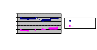
25 to 50.
Node s Vs De lay
The condition for making the decision as chances of link failure is as follows:
If the node mobility is low and the Link disconnectivity is low then the decision is made low. If the node mobility is medium and the Link dis- connectivity is low then the decision is made low. If the node mobility is high and the Link dis-connectivity is low then the decision is made medium.
If the node mobility is low and the Link disconnectivity is medium then the decision is made medium. If the node mobility is medium and the Link dis-connectivity is also medium then the decision is made medium. If the node mobility is high and the Link dis-connectivity is medium then the decision is made high.
If the node mobility is low and the Link
disconnectivity is high then the decision is made high.
If the node mobility is medium and the Link dis-
connectivity is high then the decision is made high. If
10
8
6
4
2
0
25 30 35 40 45 50
Node s
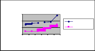
Fig 1: Nodes Vs Delay
Nodes Vs Packet Drop
15000
10000
5000
0
25 30 35 40 45 50
Node s
ANTHOCNET Ant-Fuzzy
ANTHOCNET Ant-Fuzzy
the node mobility is high and the Link dis-connectivity is also high then the decision is made very high.
Fig 2: Nodes Vs Packet Drop
IJSER © 2011
h ttp :/ / www. i jser.or g
International Journal of Scientific & Engineering Research Volume 2, Issue 9, September-2011 5
ISSN 2229-5518
1
0.8
0.6
0.4
0.2
0
Node s Vs De live ryRatio
25 30 35 40 45 50
Node s
ANTHOCNET Ant-Fuzzy
technique and adapting other ACO principles to
wireless networks.
[1] G.Vijaya Kumar, Y.Vasudeva Reddyr , and Dr.M.
Nagendra “Current Research Work on Routing Protocols for MANET: A Literature Survey,” (IJCSE) International Journal on Computer Science and Engineering 2010.
[2] P.Deepalakshmi, and Dr.S.Radhakrishnan “QoS Routing
Algorithm for Mobile Ad Hoc Networks Using ACO,”
International Conference On Control, Automation,
Fig 3: Nodes Vs Delivery Ratio
Figure 1 shows the results of average end-to-end delay for the increasing number of nodes. From the results, we can see that Ant-Fuzzy scheme has significantly lower delay than the ANTHOCNET protocol, since it has delay as one of the routing metrics. The path selected by the ant agents is delay aware and hence the end-to-end delay is less in Ant-Fuzzy.
Figure 2 shows that the Ant-Fuzzy scheme has less
packet drops than the ANTHOCNET protocol. This is because Ant-Fuzzy has the strong route maintenance scheme to mitigate the route failures. Moreover the selected path satisfies the QoS constraints delay and bandwidth and there by decreasing the number of packets dropped Since the packet drop is less, the delivery ratio is more in Ant-Fuzzy.
Figure 3 show the results of average packet delivery ratio for the varying nodes scenario. Clearly our Ant-Fuzzy scheme achieves better delivery ratio than the
ANTHOCNET scheme.
In this paper, we described an ant based routing along with the fuzzy based route failure management technique. This technique helps in finding a path between the communication end points satisfying user‟s QoS requirement without any occurrence of path failure. By simulation results, we have shown that Ant-Fuzzy has the strong route maintenance scheme and it attains good packet delivery ratio with less packet drop and delay than the ANTHOCNET scheme. There is tremendous potential for extending this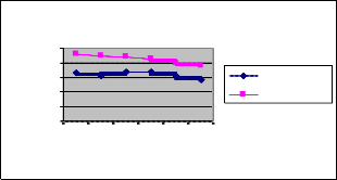
Communication And Energy Conservation - 4th-6th June 2009. [3] Mesut G¨unes, Udo Sorges, and Imed Bouazizi,“ARA – The Ant-Colony Based Routing Algorithm for MANETs,” International Workshop on Ad Hoc Networking, (IWAHN
2002)..
[4] B.R.Sujatha, and Dr. M.V. Sathyanarayana, “PBANT-
Optimized ANT Colony Routing Algorithm For Manets,”
Global Journal of Computer Science and Technology, Vol. 10
Issue 2 (Ver 1.0), April 2010.
[5] Shahab Kamali, and Jaroslav Opatrny, “A Position Based Ant Colony Routing Algorithm for Mobile Ad-hoc Networks,” Journal of Networks, Vol. 3, No. 4, April 2008.
[6] Navneet Agarwal “Ant Colony Optimization In Wireless
Ad hoc Networks Using Game Theory,” Interim Thesis
Report, DA-IICT, Gandhinagar, 2008.
[7] S.J. Mirabedini, M. Teshnehlab, M.H. Shenasa, Ali Moraghar, and A.M. Rahmani, “AFAR: Adaptive fuzzy ant based routing for communication networks,” Journal of Zhejiang University Science A, 2008 9(12): 1666-1675, 2008.
[8] S.J. Mirabedini, M. Teshnehlab, and A.M. Rahmani, “FLAR:
An Adaptive, Fuzzy Routing Algorithm for Communications Networks using Mobile Ants,” International Conference on Convergence Information Technology, 1308-1315, 2007.
[9] S.Kanna, T.Kalaikumaran, S.Karthik, and V.P.Arunachalam “Ant colony optimization for routing in Mobile Ad hoc Networks,” International Journal of Soft Computing 5(6):223-
228, 2010.
[10] Shengming Jiang, Dajiang He, and Jianqiang Rao, “A
Prediction-based Link Availability Estimation for Mobile Ad hoc Networks,” Twentieth Annual Joint Conference of the IEEE Computer and Communications Societies, INFOCOM ,
2001.
[11] Network Simulator, http://www.isi.edu/ns/nsnsam.
IJSER © 2011
h ttp :/ / www. i jser.or g