& efficiency will than 95%.When solar array placed on earth than only 25-26% energy captured which is too less than solar power from space array.
International Journal of Scientific & Engineering Research, Volume 3, Issue 11, November-2012
ISSN 2229-5518
Renewable energy: Spaced based solar Power transmission
Md. Sazzad Hossain
Abstract—Solar power satellite (SPS) is one of the sustainable sources for next generation. One of the most important technologies SPS is wireless power transmission from space to earth using microwave beam and laser beam transmission. At the earth based solar power collection, array of the panels are placed In the ground facing the sun, which collect sun’s energy during the day-time alone. In Spaced based solar power system huge solar energy present in GEO and beams it down to earth and it unaffected by the day/night 24 hours . Solar beam collection panels can consistently be exposed to high amount of solar radiation. SPS offers a complete displacement of fossil fuel, nuclear and biological sources of energy.
Index Terms –Wireless power transmission (WPT), Microwave beam, Solar power satellite(SPS), Photovoltaic array(PV
array), Rectifying antenna (Rectenna).
_ _ _ _ _ _ _ _ _ _ _ _ _ _ _ _ _ _ _ _ _ _ _ _ _ _ _ _ _ _ _ _ _
In outer space there is an uninterrupted availability of huge amount of solar power in form of light and so SPS are trying to fix at 36000 Km upper Geostationary orbit and where SPS get sunlight 24 hours and transmit energy to earth in huge amount. Also green House Effect from burning fossil will removed by Solar power Satellite. The SPS is 100% replacement of fuels, elimination of transmission line, overhead cables. No air, water pollute during generation. WPT process stands on several step and they are describe below.
From GEO heavy sun light come to solar array and this capture more sun light beam. Each m²of it will capture 1358 W energy
& efficiency will than 95%.When solar array placed on earth than only 25-26% energy captured which is too less than solar power from space array.![]()
Md. Sazzad Hossain is currently pursuing B.Sc degree program in Electrical and Electronic Engineering ,3rd year,in Rajshahi University of Engineering and Technology, Bangladesh. Ph no: +8801918168120, Email: samu.ruet.eee@gmail.com
There two method of converting sunlight beam to electricity: Photovoltaic conversion, solar dynamic conversion. Photovoltaic conversion uses semiconductor Si or GaAlAs cells to directly convert photons into electrical via a quantum mechanism. Solar cell based on 3J technology much better constructed which efficiency up to 40%. Manufacturer is trying to produce at least
37% efficient cell[11].
Table 1: Solar cell efficiency demonstration
Cell type | Demonstrated efficiency at laboratory devices | Efficiency at production devices |
Triple junction concentrator cells(GaInP/GaInAs/Ge) | 40.7% | 37% |
Single crystal GaAs | 24.7% | 22% |
Multi-crystalline Si | 20.3% | 18.5% |
Thin film CdTe on glass | 16.5% | 10.5% |
Photovoltaic cells of thin film are less efficient but are much less expensive and generally lighter. Thin film silicon solar panels are highly insensitive to ionizing radiation. In solar power
satellite implementation PV cell is glass-pane protected solar
IJSER © 2012 http://www.ijser.org
International Journal of Scientific & Engineering Research, Volume 3, Issue 11, November-2012
ISSN 2229-5518
cell panels [2]. Electrons and photons from the sun displace atoms in the cells, causing excess recombination and eventually carrier depletion type conversion. The rate of degradation depends on the type of cell, the radiation spectrum of the orbit and any shielding due to a cover glass or other coatings. Displacement damage (Dd) of solar cells can be computed by radiation spectrum in the orbit. For example after
15 years in GEO with 3 mil coverglass, Dd MeV/g, at ther damage level 3J cell’s efficiency is degraded by about 10-
15%[11].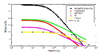
Fig 1: Solar cell efficiency as function of displacement damages
InP, CIGS and a-Si are most radiation solar cell materials. The efficiency is reduced by 50% power is an order of magnitude higher than 3J, GaAs or Si cells.
Some architecture are proposed for SPS converting DC energy to microwave beam they are: SPS 2000, Sun Tower, Modular Laser Constellation, Modular symmetrical concentrator, Perpendicular to orbital plane [11]. There architectural construction are given below.
Sun Tower (Fig 2) concept come from NASA 1995. It consists of a gravity gradient stabilized string of modular units with sun tracking inflatable Fresnel lenses to focus solar flux onto photovoltaic in GEO. A separate microwave antenna provides WPT. There a problem is that the reflectors will shadow each other during noon and midnight.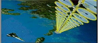
Fig 2: Sun Tower
The SPS 2000 concept (fig 3) uses a triangular prism approximately 300m on each side orbiting equatorially at an altitude of 1100km. It uses retro-directively controlled microwave power transmission and photo-voltaics . It was designed with the intent providing carbon-free power to tropical developing nations. A new subscale functional model was demonstrated in 1995 by Japan institute of space and astro-nautical science. No power is provided when spacecraft is eclipsed by the Earth ,as happens during local night.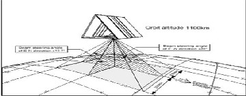
Fig 3: SPS 2000
NASA’s Aerospace corporation formulated a laser space solar power system (fig 4). The aerospace corporation formulated a laser SSP consisting of 200 individual launched laser SSP satellites. Each would beam several MW of energy to a single 1-Km diameter ground based receiving PV array. The average beam energy density intercepted by the receiver could be limited to equal solar flux at earth surface nearly 1KW/m². Weather conditions that effect atmospheric transmission qualities would
likely necessitate multiple alternate at receiving sites.
IJSER © 2012 http://www.ijser.org

International Journal of Scientific & Engineering Research, Volume 3, Issue 1
ISSN 2229-5518
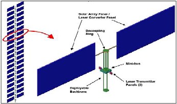
Fig 4: Modular laser constellation
The Modular symetrical concentrator (fig 5) is most popular concept in 2008 has got support from SBSP authority and NASA research and development manager John Mankins. The GEO- based system uses modularity widely and avoid concentration of large currents or voltages in the system by using eflectors to distribute solar flux power density so as to match the desired RF beam pattern on an array of solar – RF conversion ”Sandwich” module. Each module into a layer of phptovoltics, DC-RF conversion and phased array elements
Fig 5: Modular symetrical concentrator
Perpendicular to orbital structure (fig 6) don’t use gravity
gadient stability. Generally a microwave transmitting antenna of
500 to 1000 m in diameter is fed by PV arrays on the either side along an axis perpendicular to orbital plane. Attitude control and power management and distribution pose some of the challenges of the design. It deliver 5MW electric power from GEO. Flat solar reflector in ellipitical 165m 240m rims rotate about the axis to track the sun.
Fig 6: Perpendicular to orbital plane
Microwave beam conversion process are done by upper architectural transmitting section. Microwave transmission passes through antenna and microwave oscillator like Klystrons, Phase controlled magnetron (PCM), CW Magnetrons are used. Magnetron is acrossed field tube in which electron transmitted from cathode to anode via conical path. It is a self oscillatory device in which the anode contains a RF resonant structure & that is suitable for MPT. WC brown invented VCO with cooker type magnetron in a PLL that control microwave emission. 5.8GHz CW magnetron contributes to reduction in size and weight of SPS transmitting system compared to the conventional 2.45 GHz magnetron Continuous wave output klystron providing power 30KW RF to 180 KW RF and it weight
60- 340 Kg. Its DC- RF conversion efficiency 40% and Q value is high. On the contrary2.45GHz cooker-type magnetron have 70% DC-RF efficiency. PCM reduce noise and implement in phase locking of a reference signal. Phased array using PCM operate
2.45 GHz and 5.8 GHz which named as SPORTS (Space Power
Radio Transmission System)[9].
IJSER © 2012 http://www.ijser.org
International Journal of Scientific & Engineering Research, Volume 3, Issue 11, November-2012
ISSN 2229-5518
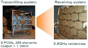
Fig 7: The SPORTS 5.8GHz magnetron DC-to-RF converter and rectenna arrays.
All control microwave beam in high resolution. Gyrotrons are available for operate DC to RF high power up to 100KW at 94
GHz at efficiency up to 50% to 60%. A light microwave power transmitter operate at 5.8GHz named COMET (Compact Microwave Energy Transmitter). Now researcher invent Phase and Amplitude Controlled Magnetron (PACM) which operate in
2,45GHz & 5.8GHz. In transmission an alternating current is created in the element by applying a voltage at the antenna terminals and causing the element to radiate electromagnetic field. High frequency and low noise WPT is important since a SPS is necessary to ensure electromagnetic compatibility (EMC) with other radio applications.
Since magnetron is too complicated to analyze theoretically
,the 3-D computer simulation of magnetron will help for higher efficiency operation and also allow loss and lightweight power divider and a low loss phase shifter are necessary for the high efficient WPT system. The transmitting antenna need to be high capable to transmit microwave beam. Some antenna model of various organization are given below.
Table 2:Typical parameters of the transmitting antenna of the
JAXA: Japan Aerospace Exploration Agency, JAPAN NASA: National Aeronautics & Space Administration, USA DOE: Department Of Energy, USA
Microwaves beam are transmitted from SPS from GEO to earth and it is situated on the EM spectrum with frequencies ranging from 0.3 to 300 GHz. According to Friis transmission formula received power from far place as follows;![]()
(1)
![]()
![]()
(2) (3)
Here Pr, Pt, Ar, At, , D are gradually Received power, Transmitted power, Aperture area of receiving antenna, Aperture area of transmitting antenna, wavelength, Distance from transmitting antenna to receiving antenna. is a parameter it also refers efficiency of Friis equation[10].
For transferring beam from GEO orbit beam efficiency, η at equation (3) need to be large than we get much power at receiver rectenna. Distance D is so large and the aperture area of Ar and At should not be large for the sake of size
reduction. So should to be more small that prefer it need high frequency beam as like microwave. The microwave
radiation is very diffusive in nature so there rectenna must
large in size. For accurate target beam forming need to be retro-directive system (Corner reflector, Van Atta array) and directed point to point using parabolic antenna (Drum antennas). Van Atta array is made of pairs of antenna spaced equidistant from the center of the array [3]. The received signal
of one antenna is re-radiated by its pair antenna. The retro-
IJSER © 2012 http://www.ijser.org
International Journal of Scientific & Engineering Research, Volume 3, Issue 11, November-2012
ISSN 2229-5518
directive system unifies target detection with beam forming by the phase conjugate circuits.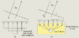
Fig 8: Retro-directive system : (a) Van atta array ,(b) phase conjugating system
The target is detected by pilot signaland after target we need to form accurate microwave beam and this called “software retro-directive”. Japan have developed PLL-Heterodyne type retro-directive system which generate pilot signal microwave beam 3.85 GHz & 5.77 GHz frequencies are used[10]. Block diagram of power transmission system using pilot signal are shown below;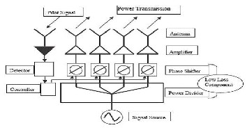
Fig 9 : Power transmission system using pilot signal.
If frequency windows nearly 2.45-5.8GHz and also 35-38GHz then atmospheric interference losses comes to 2-6% and 8-11% respectively.
Rectenna and cyclotron wave converter (CWC) are use for convert RF energy to DC power and send it to power grid. CWC is a microwave tube which rectify high power microwave into DC. Tested efficiency of CWC nearly
70-74%.[1] This typical rectenna based on four elements:
antenna, low pass filter (LPF), Ga-As Schottky diode and DC
pass filter capacitor [11]. Schematic designed antenna are given below;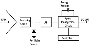
Fig 10: Schematic of antenna and associated power management circuit
The RF power Prf received by the antenna is a function of the Incident power density (S) , effective area of the antenna (Aeff), incident angle and frequency. The DC power calculated from RF power, convertion efficiency and the DC load impedence (Zdc). The fluctuation in the incident power density will alter the conversion efficiency and subsequently the outout Pdc power at rectenna at eqn(5):![]()
(4) (5)
Initial development of rectenna focuses on its directivity and
efficiency for great power reception and conversion, hence, large array was usually adopted for microwave power reception. For SPS applications the transmitting antenna will operate with a Gaussian beam in order to achieve high power and high conversion efficiency. Afterwards many function are added to enhance the performance of rectenna array such as arbitrary polarization, dual polarization, dual band. Circular polarization is also use to eliminate the need to maintain alignment with the electric field polarization of transmitting antenna . Unwanted harmonics generated in the operation of rectenna and LPF can suppress harmonics to improve the system. For size reduction and cost reduction micro-strip rectenna use for that. Others Yagi-Uda antenna, parabolic antenna, patch antenna use as are rectenna and among its patch antenna works well [3]. This type of antenna has approximately 90% efficiency at 2.45 GHz .Some antennas
performance are given below [8]:
IJSER © 2012 http://www.ijser.org
International Journal of Scientific & Engineering Research, Volume 3, Issue 11, November-2012
ISSN 2229-5518
Table 3: Rectifying antenna model
Fig 12: Cost of Coal power Escalates With Fuel cost
After producing large of DC energy it transform into AC energy by cycloconverter. There’s many SPS plant design for producing 1.2-4.8 GW. Than huge amount of electricity pass through transmission line and the power grid decided to how much power it distributed to human.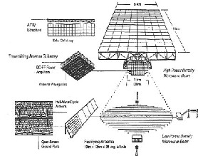
Fig 11: 1.2 GW SPS designed model
Spaced Solar power scientist & engineers predicted some comparison of Fuel & Solar Power for the upcoming years. Where renewable energy overcome the cost of fuel and fulfill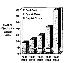
power crisis [6].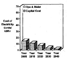
Fig 13: Cost of SPS energy in lieu of fuel cost
Recent studies inform that every energy source decreases day by day and to overcome that renewable power demand increase within 13 year. Overall changes are given below.
Table 4: Energy demand changes in upcoming days
Average Projected | Absolute Change | Necessary growth(%) | Necessary Annual |
IJSER © 2012 http://www.ijser.org
International Journal of Scientific & Engineering Research, Volume 3, Issue 11, November-2012
ISSN 2229-5518
but controlling all system SPS survive lot of energy to human. In order to SPS to become reality the government support, Cheaper launch prices &involvement to private sector needed.
For human & atmospheric safety SPS need to install in free region like desert, sea side. There’s many requirement to establish it according to Current U.S developing SPS Program.
NASA, NSF (National Science Foundation) & EPRI (Electric Power Research Institute) have installed some key challenges in future SPS system [8]:
1. Radical improvements in WPT, with primary emphasis on solid-state device issues central to solid-state transmission by microwave.
2. Improved power management, distribution, control with a special emphasis on reducing mass.
3. More intelligent robotics need to assembly the SPS
structure in space with minimal human task.
4. Understanding of cost & opportunities & how to optimize them for the net impact on the environment, health, safety i.e to biosphere, Ionosphere& sustainable growth around world.
Solar panels nearly 125% effective in space[5]. Besides SPS
[2]. Wireless power transmission of space based solar power by Barathwaj. G,Srinag.K ,2011 2nd International conference science and technology, IPCBEE vol.(2011)©(2011)IACSIT press,Singapore.
Fan, Harold Matin, James Wu, Brian Mok ,2 Feb 2011
Stellites”,IEEE AES Systems Magazine, Janauary ,1996
Systems,2006
Technology,IEEE microwave magazine, ISSN 1527-3342/02©2002 IEEE.
Solar Power Station/Satellite, by Tomohiko Mitani, Naoki Shinohara, Kozo
nd
by microwave, Laser system are also effective it works on
Hashimoto, A-006(o),2
Joint international conference on “Sustainable Energy
solar beam to DC power in solar array than DC energy transmitted by laser beam finally at receiver laser beam transform to DC energy .
The solar power satellite technology may overcome our power crisis. The CO₂ gas emission which is threat for global worming will be minimized by SPS . Though there’s atmospheric effect
and Environment”21-23 Nov,2006
10-05
IJSER © 2012 http://www.ijser.org