Inte rnatio nal Jo urnal o f Sc ie ntific & Eng inee ring Re se arc h Vo lume 3, Issue 1 , January - 2012 1
ISS N 2229-5518
Region Filling and Object Removal by Exemplar- Based Image Inpainting
Mrs.Waykule J.M., Ms. Patil V.A.
Abs tract— A new algorithm is proposed f or removing large objects f rom digital images. The challenge is to f ill in the hole that is lef t b ehind in a visually plausible w ay. In the past, this problem has been addressed by tw o classes of algorithms: (i) “texture synthesis” algorithms f or generating large image regions f rom sample textures, and (ii) “inpainting” techniques f or f illing in small image gaps. The f ormer has been demonstrated for “textures” – repeating tw o-dimensional patterns w ith some stochastic; the latter f ocus on linear “structures” w hich can be thought of as one - dimensional patterns, such as lines and object contours. This paper presents a nov el and eff icient algorithm that combines the advantages of these tw o approaches.
Index Terms— Image Inpainting, Texture Synthesis, Simultaneous Texture and Structure Propagation.
—————————— ——————————
1 INTRODUCTION
New algorithm is proposed for removing large objects from digital images. The challenge is to fill in the hole that is left behind in a visually plausible way.
Figure 1 show an example of this task, where the foreground
person (manually selected as the target region) is automatically
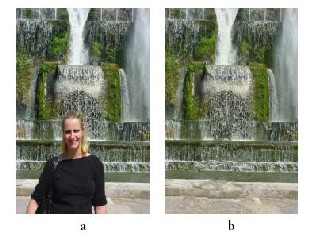
replaced by data sampled from the remainder of the image
Fig. 1 Removing large objects from images. (a) Original pho-
tograph. (b) The region corresponding to the foreground per- son (covering about 19% of the image) has been manually s e- lected and then automatically removed. Notice that the hori- zontal structures of the fountain have been synthesized in the occluded area together with the water, grass and rock textures.
———— ——— ——— ——— ———
Mrs. Waykule J.M. is pursuing masters degree program in electronics engineering in Shivaji University, Maharashtra, PH -9422525671. E-mail: jyoti.tate@Gmail.com
Ms. Patil V.A is currently pursuing masters degree program in electronics engineering in Shivaji University, Maharashtra, PH -9975035677. E-mail:
viddulata@Gmail.com
(This information is optional; change it according to your need.)
2. PRES ENT THEORY AND P RACTICES
In the past, this problem has been addressed by two classes of algorithms: (i) "texture synthesis" algorithms for generating large image regions from sample textures, and (ii) "inpainting" techniques for filling in small image gaps. The former work well for "textures" -- repeating two-dimensional patterns with some stochastic; the latter focus on linear "structures" which can be thought of as one-dimensional patterns, such as lines and object contours.
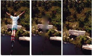
Fig.2 Removing large objects from photographs. a) Original image b) The result of region filling by traditional
image inpainting. Notice the blur introduced by the diffusion process and the complete lack of texture in the synthesized area c) The final image where the bungee jumper has been completely removed and the occluded region reconstructed by our automatic algorithm
IJSER © 2012
http :// www.ijser.org
Inte rnatio nal Jo urnal o f Sc ie ntific & Eng inee ring Re se arc h Vo lume 3, Issue 1 , January - 2012 2
ISS N 2229-5518
3. KEY OBSER VAT IONS
3.1 Exemplar-based syn the si s suffice s
The core of our algorithm is an isophote-driven image sam- pling process. It is well-understood that exemplar-based ap- proaches perform well for two-dimensional textures [1], [11],[17]. But, we note in addition th at exemplar-based texture synthesis is sufficient for propagating extended linear image structures, as well; i.e., a separate synthesis mechanism is not required for handling isophotes.
The core of our algorithm is an isophote-driven image sam-
pling process. It is well-understood that exemplar-based ap- proaches perform well for two-dimensional textures [1], [11],[17]. But, we note in addition that exemplar-based texture synthesis is sufficient for propagating extended linear image structures, as well; i.e., a separate synthesis mechanism is not required for handling isophotes.
Figure 3 illustrates this point. For ease of comparison, we adopt notation similar to that used in the inpainting literature. The region to be filled, i.e., the target region is indicated by Ω, and its contour is denoted δΩ. The contour evolves inward as the algorithm progresses, and so we also refer to it as the ―fill front‖. The source region, Ф which remains fixed throughout the algorithm, provides samples used in the filling proces s.
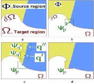
Fig.3 Structure propagation by exemplar-based texture syn- thesis. (a) Original image, with the target region Ω, its contour δΩ, and the source region Φ clearly marked. (b) We want to synthesize the area delimited by the patch centered on the point p ε ∂Ω. (c) The most likely candidate matches for
  lie along the boundary between the two textures in the source region e.g.
  and
and  (d) The best matching patch in the
candidates set has been copied into the position occupied by
, thus achieving partial filling of  . Notice that both tex-
ture and structure (the separating line) have been propagated inside the target region. The target region Ω has, now, shrunk and its front δΩ.has assumed a different shape.
The user will be asked to select a target region, Ω, manually. (a) The contour of the target region is denoted as δ Ω. (b ) For
every point p on the contour δΩ, a patch Ψp is constructed, with p in the centre of the patch. A priority is calculated based on how much reliable information around the pixel, as well as the isophote at this point. (c) The patch with the highest priori- ty would be the target to fill. A global search is performed on the whole image to find a patch, Ψq that has most similarities with Ψp. (d) The last step would be copy the pixels from Ψq to fill Ψp. With a new contour, the next round of finding the patch with the highest continues, until all the gaps are filled.
3.2 Filling order is critical.
The previous section has shown how careful exemplar-based filling may be capable of propagating both texture and stru c- ture information. This section demonstrates that the quality of the output image synthesis is highly influenced by the order in which the filling process proceeds. Furthermore, we list a number of desired properties of the ―ideal‖ filling algorithm.
A comparison between the standard concentric layer filling (onion-peel) and the desired filling behavior is illustrated in fig. 3. Figures 3b,c,d show the progressive filling of a concave target region via an anti-clockwise onion-peel strategy. As it can be observed, this ordering of the filled patches produces the horizontal boundary between the background image re- gions to be unexpectedly reconstructed as a curve.
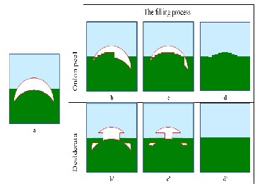
Fig. 4 The importance of the filling order when dealing with concave target regions. (a) A diagram showing an image and a selected target region (in white). The remainder of the image is the source. (b,c,d) Different stages in the concentric-layer fil- li ng of the target region. (d) The onion -peel approach pro- duces artifacts in the synthesized horizontal structure. (b‘, c‘, d‘) Filling the target region by an edge-driven filling order achieves the desired artifact-free reconstruction. (d‘) The final edge-driven reconstruction, where the boundary between the two background image regions has been reconstructed cor- rectly.
A better filling algorithm would be one that gives higher priority of synthesis to those regions of the target area which
IJSER © 2012
http :// www.ijser.org
Inte rnatio nal Jo urnal o f Sc ie ntific & Eng inee ring Re se arc h Vo lume 3, Issue 1 , January - 2012 3
ISS N 2229-5518
lie on the continuation of image structures, as shown in figs.
3b‘,c‘,d‘. Together with the property of correct propagation of linear structures, the latter algorithm would also be more ro- bust towards variations in the shape of the target regions. A concentric-layer ordering, coupled with a patch -based filling may produce further artifacts (cf. fig. 4) Therefore, filling order is crucial to non-parametric texture synthesis [1], [6], [12], [15]. To our knowledge, however, designing a fill order which ex- plicitly encourages propagation of linear structure (together with texture) has never been explored, and thus far, the de- fault favorite has been the ―onion peel‖ strategy. Another de- sired property of a good filling algorithm is that of avoiding
―over-shooting‖ artifacts that occur when image edges are allowed to grow indefinitely. The goal here is finding a good balance between the propagation of structured regions and that of textured regions (fig. 3b‘, c‘, d‘), without employing two adhoc strategies. As demonstrated in the next section, the algorithm we propose achieves such a balance by combining the structure ―push‖ with a confidence term that tends to re- duce sharp in-shooting appendices in the contour of the target region.
As it will be demonstrated, the filling algorithm proposed in this paper overcomes the issues that characterize the tradi- tional concentric-layers filling approach and achieves the de- sired properties of: (i) correct propagation of linear structures, (ii) robustness to changes in shape of the target region, (iii) balanced simultaneous structure and texture propagation, all in a single, efficient algorithm. We now proceed with the d e- tails of our algorithm.
4. OUR REGION-FILLING ALGOR ITHM
First, given an input image, the user selects a target region, Ω,
to be r emoved and filled. The source region, may be defined as the entire image minus the target region (Ф = I- Ω,), as a dilated band around the target region, or it may be manually specified by the user.
Algorithm iterates the following three steps until all pixels have been filled.
1) Computing Patch Priorities.
2) Propagating Texture and Structure Information.
3) Updating Confidence Values.
1) Computing Patch Priorities:
The priority computation is biased toward those patches
which:
a) Are on the continuation of strong edges.
b) Are surrounded by high-confidence pixels. Given a patch
 centered at the point ‗p‘.We defines its priority
as the product of two terms:

 The confidence term that measure of the amount of
reliable information surrounding the pixel ‗p‘
 The data term that is a function of the str engt h of iso- photes hitting the fr ont ∂Ω at each iteration.

D( p)


Wher e, (a) estimated as the unit vector orthogonal to
the fr ont ∂Ω... Is the isophote (dir ection and intensity)
at point ‘p’ It computed as the maximum value of the image gradient in  (c) α=Normalization factor (e.g. For Gray level it is α=255)
2) Propagating Texture and Structure information
Propagate image texture by direct sampling of the source re- gion, the distance  between two generic patches
and  is simply defined as the sum of squared differences.
3) Updating Confidence Values


After the patch has been filled with new pixel values, the confidence is updated in the area delimited by

5. SOME P ROPE RTIES OF EX EMPL AR - BAS ED I MAGE INPAINTING ALG ORITH M
The effect of the confidence term is that of smoothing the
contour of the target region by removing sharp appendices and making the target contour close to circular. . Notice that (1) only dictates the order in which filling happens. The use of image patches for the actual filling achieves texture synthesis [11]. Furthermore, since the fill order of the target region is dictated solely by the priority function P(p), we avoid having to predefine an arbitrary fill order as done in existing patch - based approaches [11], Our fill order is function of image properties, resulting in an organic synthesis process that el i- minates the risk of ―broken-structure‖ artifacts (as in fig. 11f). Furthermore, since the gradient-based guidance tends to propagate strong edges, blocky and misalignment artifacts are reduced (though not completely eliminated), without a patch - cutting (quilting) step [11] or a blur-inducing blending step. It must be stressed that our algorithm does not use explicit nor implicit segmentation at any stage. For instance, the gradient operator in (1) is never thresholded and real valued numbers are employed.
6. IMPLEMENTATION DETAILS
In our implementation the contour ∂Ω of the target region is
modelled as a dense list of image point locations. These points are interactively selected by the user via a simple drawing interface. Given a point , the normal direction np is computed as follows: i) the positions of the ―control‖ points of
∂Ω are filtered via a bi-dimensional Gaussian kernel and, ii) np
is estimated as the unit vector orth ogonal to the line through
IJSER © 2012
http :// www.ijser.org
Inte rnatio nal Jo urnal o f Sc ie ntific & Eng inee ring Re se arc h Vo lume 3, Issue 1 , January - 2012 4
ISS N 2229-5518

the preceding and the successive points in the list. Alternative implementation may make use of curve model fitting. The gradient is computed as the maximum value of the image gradient in . Robust filtering techniques may also be employed here. Finally, pixels are classified as belonging to the target region , the source region
  or the remainder of the image by assigning different values to their alpha comp o- nent. The image alpha channel is, therefore, updated (locally) at each iteration of the filling algorithm.
7. RESULT AND COMPARISIONS
Here we apply our algorithm to a variety of images, ranging
from purely synthetic images to full-color photographs that include complex textures. Where possible, we make side-by- side comparisons to previously proposed methods. In other cases, we hope the reader will refer to the original source of our test images (many are taken from previous literature on inpainting and texture synthesis) and compare these results with the results of earlier work.
In all of the experiments, the patch size was set to be greater
than the largest texel or the thickest structure (e.g., edges) in the source region. Furthermore, unless otherwise stated the source region. All experiments were run on a 2.5GHz Pentium IV with 1GB of RAM.
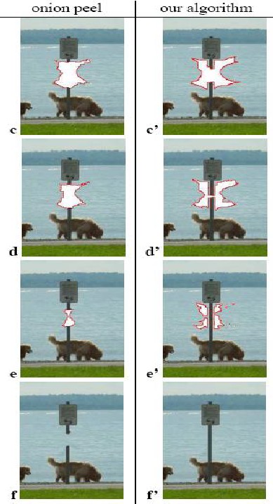
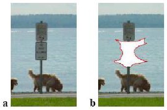
Figure5 shows yet another comparison between the concentric filling strategy and the proposed algorithm. In the presence of concave target regions, the ―onion peel‖ filling may lead to visible artifacts such as unrealistically broken structures (see the pole in fig. 11f). Conversely, the presence of the data term of (1) encourages the edges of the pole to grow ―first‖ inside the target region and thus correctly reconstruct the complete pole (fig. 11f‘). This example demonstrates the robustness of the proposed algorithm with respect to the shape of the s e- lected target region tend to have large priority values ass o- ciated with them.
.
Fig. 5 Onion peels vs. structure-guided filling. (a) Original image. (b) The target region has been selected and marked with a red boundary. (c, d, e, f) Results of filling by concentric layers. (c‘, d‘, e‘, f‘) Results of filling with our algorithm. Thanks to the data term in (1) the sign pole is reconstructed correctly by our algorithm
IJSER © 2012
http :// www.ijser.org
Inte rnatio nal Jo urnal o f Sc ie ntific & Eng inee ring Re se arc h Vo lume 3, Issue 1 , January - 2012 5
ISS N 2229-5518
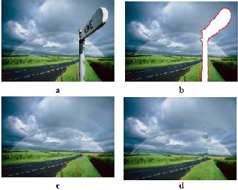
Fig. 6 Comparisons with Jia et al. ―Image Repairing‖ [16]. (a) Original input image. (b) The manually selected target region. (c) The resulting region-filling achieved by Jia et al. (d) the result of our region-filling algorithm. The missing portion of rainbow is reconstructed convincin gly. Figures (c) and (d) are of comparable quality, but our algorithm avoids the image segmentation step with considerable increase in speed.
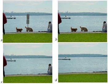
Fig. 7 R emoving th e multipl e obj ects fro m phot ographs. (a) Original photograph of Kirkland (W A). (b,c,d) S everal o b- jects are sequ entially remo ved. N otice how w ell the shore line and other structur es have been rec onstructed.
8. CONC LUSION AND FUTURE WORK
This paper has presented a novel algorithm for removing large objects from digital photographs. The result is an image in
which the selected object has been replaced by a visually plausible background that mimics the appearance of the source region
Our approach employs an exemplar-based texture synthesis technique modulated by a unified scheme for determining the fill order of the target region. Pixels maintain a confidence value, which together with image is ophotes, influence their fill priority.
The technique is capable of propagating both linear structure and two-dimensional texture into the target region with a sin- gle, simple algorithm. Comparative experiments show that a simple selection of the fill order is necessary and sufficient to handle this task.
Our method performs at least as well as previous techniques
designed for the restoration of small scratches, and, in i n- stances in which larger objects are removed, it dramatically outperforms earlier work in terms of both perceptual quality and computational efficiency.
Moreover, robustness towards changes in shape and topology of the target region has been demonstrated, together with oth- er advantageous properties such as:
Advantages
a) Preservation of edge sharpness
b) No dependency on image segmentation
c) Balanced region filling to avoid over-shooting artifacts
d) Patch-based filling helps achieve: (i) speed efficiency, (ii) Accuracy in the synthesis of texture (less garbage grow- ing), and finally (iii) accurate propagation of linear stru c- tures.
Disadvantages
a) The synthesis of r egions for which similar patches do not exist does not pr oduce r easonable results (a pro b- lem c ommon to [10], [19]);
b) The algo rithm is no t d esign ed to handle cu rved struc-
tures
c) Our algorith m d oes no t handle depth ambiguities (An expression whose meaning cannot be deter mined fro m its context) (i.e., what is in front o f what in the occluded area?).
Curren tly, w e are investi gating the p ossibility of construc t- ing Gr ound-truth data and designing evaluation tests that would allow us to quantify the p erfor mance of each algo- rithm. This turns ou t to be a non -tri vial task. Fu rther more we are in vestigating extensions of the curr ent algori thm to handle accurate propagation of curved structur es in still photographs as well as r emovin g o bjects fro m vid eo, which promise to imp ose an entir ely n ew set of challenges.
REFERENCES
[1] A.Criminisi*, P. Perez and K.Toyama. ―Region Filling and Object Removal by Exemplar-Based Image inpainting‖ IEEE TRANSACTION ON IMAGE PROCESSING, VOL. 13, NO. 9, SEP 2004
[2] P.Harrison. ―A non-hierarchical procedure for re-synthesis of complex tex-
ture.‖ In Proc. Int. Conf. Central Europe Comp. Graphics, Visua. and Comp.
Vision, Plzen, CzechRepublic, February 2001
[3] M.Bertalmio, L. Vese, G. Sapiro, and S. Osher. ―Simultaneous structure and texture image inpainting.‖ In Proc. Conf. Comp. Vision Pattern Rec., Madi-
son, WI, 2003
IJSER © 2012
http :// www.ijser.org
Inte rnatio nal Jo urnal o f Sc ie ntific & Eng inee ring Re se arc h Vo lume 3, Issue 1 , January - 2012 6
ISS N 2229-5518
[4] I. Drori, D. Cohen-Or, and H. Yeshurun. ―Fragment-based image comple- tion.‖ InACMTrans. on Graphics (SIGGRAPH 2003 issue), 22(3), volume 22, pages 303–312, SanDiego, US, 2003
[5] A.Efros and T. Leung. ―Texture synthesis by non-parametric sampling.‖ In Proc. Int. Conf. Computer Vision, pages 1033–1038, Kerkyra, Greece, Septem- ber1999
[6] A.Efros andW.T. Freeman. ―Image quilting for texture synthesis and trans-
fer‖. In Proc. ACMConf. Comp. Graphics (SIGGRAPH), pages 341–346, Eu- gene Fiume, August 2001
[7] A.Efros andW.T. Freeman. ―Image quilting for texture synthesis and trans-
fer‖. In Proc. ACMConf. Comp. Graphics (SIGGRAPH), pages 341–346, Eu- gene Fiume, August 2001
[8] C.Ballester, V. Caselles, J. Verdera, M. Bertalmio, and G. Sapiro.―A variational
model forfilling-ingray level and color images.‖ In Proc. Int. Conf Computer
June 2001
[9] J.S.De Bonet.‖ Multiresolution sampling procedure for analysis and synthesis of texture images.‖ In Proceedings of SIGGRAPH 1997
[10] D.Garber. Computational Models for Texture Analysis and Texture Synthe- sis.PhD thesis, University of Southern California, 1981
[11] M.M.Olivieira, B. Bowen, R. Mckenna, and Y. S. Chung, "Fast Digital Inpaint-
ing", Sep 2001
[12] T.F.chan and J.Shen,‖Mathematical model for local non-texture inpainting,‖
2001
[13] R.J.Cant and C. S. Langensiepen, "A Multiscale Method for utomated I n- painting", ESM2003, 2003
[14] J.Portilla and E.P.Simoncelli, ―A parametric texture coefficients,‖ International
Journal of Computervision,vol. 40, no. 1, pp. 49–70, 2000
[15] D.J.Heeger and J.R.Bergen,―Pyramid-based texture nalysis/synthesis,‖in
SIGGRAPH, 1995 , pp. 229–238.
[16] J.Jia and C.-K. Tang, ―Image repairing: Robust image synthesis by adaptive
and tensor voting,‖cvpr, vol. 01, p. 643, 2003 [17] Websites:
http://www.mathworks.com/
http://www.ieeexplore.ieee.org/ [18] Reference Books:
a) Rafael C. Gonzalez , Richard E.Woods, ―Digital Image Processing ‖ .
b) A. K. Jain.‖ Fundamentals of Digital Image processing‖
IJSER © 2012
http :// www.ijser.org