
International Journal of Scientific & Engineering Research, Volume 3, Issue 11, November-2012 1
ISSN 2229-5518
Radiation pattern optimization by Apicalis Ant algorithm for smart Array antennas
Debbat F, Bendimerad F. T.
Abstract—In modern mobile communications systems, both desired and interfering signals change their directions continuously. Therefore, a fast tracking system is needed to constantly track the users and then adapt the radiation pattern of the antenna to direct multiple narrow beams to desired users and nulls interfering sources. This paper proposes a smart array antenna system, which can improve performance by spatial filtering. Smart array antennas backed by strong signal processing algorithms are able to automatically change the beam pattern in accordance with the changing signal environment. The adaptation is achieved by multiplying the incoming signals with complex weights and then summing them together to obtain the desired radiation pattern. Adaptive array optimization is an NP-hard problem. In this paper, a technique based on the API (Pachycondyla Apicalis algorithm) is presented to solve this problem. Several illustrative examples of patterns with imposed single and multiple null directions are given to show the versatility of the present method.
Index Terms— Smart arrays antenna, Radiation pattern, Beamforming, Optimization, Metaheuristic, API.
—————————— ——————————
n recent years a substantial increase in development of broadband wireless access technologies for evolving wireless internet services and improved cellular system has been observed because of them there is traffic that demands on both the manufacturer and operators to provide sufficient capacity in the networks. This becomes major challenging problems for service provider to solve since there exist certain negative factors in the radiation environment contributing to limit the capacity. As the growing demand for mobile communications is constantly increasing, the need for better coverage, improved capacity, and higher transmission quality rises. Thus, a more efficient
use of the radio spectrum is required.
Smart antenna systems [1] are capable of efficiently
utilizing the radio spectrum and are a promise for an
effective solution to the present wireless systems problems
while achieving reliable and robust high-speed, high-data-
rate transmission.
The increasing pollution of the electromagnetic environment has prompted the study of array pattern
nulling techniques. These adaptive techniques are very important for minimising degradation in signal-to-noise ratio performance due to undesired interferences. The adaptation is achieved by multiplying the incoming signals with complex weights and then summing them together to obtain the desired radiation pattern. Adaptive array optimization is an NP-hard problem [2-10].
The techniques of placing nulls in the antenna patterns to suppress interference and maximizing their gain in the direction of desired signal have received considerable attention in the past and are still of great interest using evolutionary algorithms such as genetic algorithms (GA) [11, 12] or the sequential quadratic programming (SQP) algorithm [13].
In this work we present an optimization metaheuristic method based on a model of the foraging behavior of a population of primitive ants (Pachycondyla Apicalis) to determine the optimal radiation pattern for an adaptive linear array antenna. These ants are characterized by a relatively simple but efficient strategy for prey search in which individuals hunt alone and try to cover a given area
around their nest [14].
The remainder of this paper is organized as follows. Section 2 briefly exposes the metaheuristic method (API) principle. Section 3 presents the strategy of array antennas optimization by API and analyzes the simulation results. Section 4, as a conclusion, summarizes our principal observations.
In this paper, we are interested in a model of the foraging strategy of the Pachycondyla apicalis ponerinants [14, 15] and in its application to adaptive array antennas optimization problems. These ants use relatively simple principles to search their preys, both from global and local view-points. Starting from their nest, they globally cover a given surface by partitioning it into many hunting sites. Each ant performs a local random exploration of its hunting sites and its site choice is sensitive to the success previously met on the sites. These principles can be used to implement a new strategy for the search of a global minimum of a function ƒ in a search space S.
The stepwise procedures of the API algorithm are described as following [15]:
1) Initialization: set the algorithm parameters.
2) Generation of new nest (exploration)
3) Exploitation
3.1) Intensification search:
For each ant , if has less than hunting sites in its memory,
then create a new site in the neighborhood of and exploit
this new site;
Else If the previous site exploitation is successful, then
exploit the same site again;
else exploit a probabilistically selected site (among its sites
in memory).
The following diagram illustrates the principle of
intensified research by each ant.
IJSER © 2012 http://www.ijser.org
International Journal of Scientific & Engineering Research, Volume 3, Issue 11, November-2012 2
ISSN 2229-5518
Fig 1. The behavior model of a Pachycondyla Apicalis ant 𝑎 [14]
weighting.
![]()
There are several methods for combining the received signals in a multi-antenna array, but the simplest conceptually is to multiply the signal vector by the complex array weight vector and then to sum over the N antenna elements in the array. The receiving beamformer is shown in Figure 2. In this receiving beamformer, each signal x is multiplied by a complex weight w and summed to form the output of the array denoted by Y.
The output of beamformer at time t is given by:
( ) ∑ ( ) (1)
Where * denotes the complex conjugate and (.) denotes
hermitian (complex conjugate) transpose operation. The vectors w and x, referred to as array weight vector and the array signal vector, respectively, are:
[ ] (2)
[ ( ) ( ) ( )] (3)
Where T denotes the transpose operation. The array signal
ns p
the ant. e j
represents the number of sites memorized by represents the number of unsuccessful
vector x can also be written as:
explorations successively performed by the ant on site j .
3.2) Information sharing
Probabilistically replace a site in the memory of the ant by
the best one searched so far in this cycle.
3.3)Nest movement:
If the condition for nest movements is satisfied, go to (4);
otherwise, go to (3.1).
4)Termination test:
If the test is passed, stop; otherwise, empty the memories of
all ants and then go to (2).
3.1 Adaptive array antennas problem formulation
The goal of array antennas is to combine received signals in such a way that the ratio of desirable to undesirable content in the array output is maximized.
( ) ( ) ( ) ∑ ( ) ( ) ( ) (4)
where s and s are the desired and interfering signals
arriving at the array at an angle θ and θ , respectively, L is
the number of interfering signals, and N is the gaussian
noise at the array elements. (θ ) and (θ ) are the steering
vectors for the desired and interfing signals, respectively
(θ) is given by :![]()
![]()
𝑎( ) [ ( ) ( ) ( ) ] (5)
Where λ is the wavelength.
The weights selection process is carried out by adaptive algorithms which build reference signals by a preestablished knowledge of the communication signals structure or a portion of the data transmitted [4-9]. Consider a uniformly spaced linear array with M omnidirectional antenna elements shown in Figure 3 . Interelement spacing is d and the plane wave front is impinging upon the array at an angle of θ with respect to the array normal.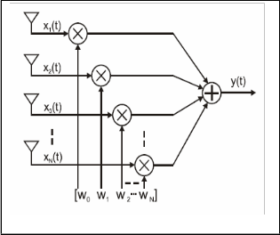
dsin
θ
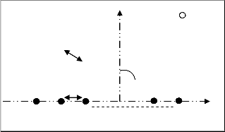
Fig.2. Narrow band array antennas with a complex
d
Fig 3. Uniformly spaced linear array antennas
IJSER © 2012 http://www.ijser.org
International Journal of Scientific & Engineering Research, Volume 3, Issue 11, November-2012 3
ISSN 2229-5518
We admit there does not exist coupling between the sources, and that each source, in presence of the others,
X K j 1 X K
j Oexplo
( X K
j)
(9)
rayon the same field f(θ) . The total field radiated by the
linear array antennas, will be the sum of the various
contributions of the fields radiated by each source weighted
by a excitation coefficient.
N 1
(in intensification phase)
Where k is index of ant, j represents the algorithm iteration
𝑂 and 𝑂 , transformers determined by the
experiment.
F
f ai exp jk0id sin cos bi
i0
(6)
The solutions evaluation (phase vectors) is done according to the minimization criterion of the cost function (eq. 7)
Where θ et φ: observation angles , : amplitude of the element i excitation , b : phase of the element i excitation,
d : inter-element spacing, f(θ) : radiation pattern of an
element of the array antennas and k : wave number.
By varying the phase b and amplitude of the feeding
currents to the elements, the overall array pattern can be
steered in the desired user's direction and minimizing the
radiation levels in the interferences directions without
physically moving any of the individual elements.
For reducing the complexity and the obstruction of the array antennas feeding system, the approach used here is to
fix the amplitude of weighting and to seek only the law of optimal phase only by hybrid API.
The objectif fonction is:
It is also necessary to store the last solutions visited in a dynamic vector tabk which contains the list of the solutions visited by the ant k.
During the algorithm execution, we will retain the absolute optimum among the minima generated during all the algorithm unfolding. The stop criterion is fixed according to a certain iteration number chosen initially.
The following algorithm presents the essential phases of the adaptation by l' API:
- (1) Initialization of the parameters:
API ( , T, stopping criterion ) , array antennas, useful signal and interferences.
- (2) Choose randomly the initial nest location
M 1 N
S /* best phase vector (initially)
fitness 20 log10 si f(θi )a n exp jk 0 ndsinθ n cosφ n b n
(7)
i1
n 1
- (3) Random generation of the N ants /* N phase vectors
- (4) for each ant (phase vector ) , [ ]:
If has less than p hunting sites in memory
Where M: number of interferences, and 𝑆 : space vector of
sources.
The strategy adopted here, consists in overall modifying population of initial solutions repeatedly to lead to a satisfactory final solution in a reasonable time.
For this purpose, the API method uses movements to pass from a solution to another inside a research space. It is divided into two essential iterative phases: a diversification phase for the promising solution detection by applying Orand stochastic operator, followed by an intensification phase to intensify research in the zone of this solution by applying Oexplo stochastic operator, for finding the best phase vector.
The algorithm starts with a random generation of F
solutions. Each solution corresponds (hunting site: point in
research space) to a vector phase 𝑋( ), N
represents the number of antennas and F the number of ants.
The solutions generated initially are well dispersed in the
research space [- π, π].
Each ant begins its research with the disturbance of the corresponding solution, by applying a stochastic
transformation presented by:
(dynamic vector tabk) then Create a new site in the neighborhood of S and Explore this created site.
/* application of Orand operator to generate and memorize a whole of favorite /*phase vectors.
Else
If the previous site exploration was successful
then Explore again the same site. /* application of Oexplo operator for finding the best phase vector /*in this zone
Else Explore a randomly selected site
(among the p sites in memory).
- (5) Remove from the ants memories all sites
(the favorite phase vectors) which have been explored
unsuccessfully more tha (𝑎 )n consecutives times.
- (6) Perform recruitment (best phase vector copying
between two randomly selected ants)
- (7) If more than T iterations have been performed
then Change the nest location ( best solution 𝑆 ) and
Reset the memories of all ants.
- (8) Go to (4) or stop if a stopping criterion is satisfied.
P: hunting sites (favorite phase vectors) in the neighborhood of S
(𝑎 ) times without catching any prey (not solution
improvement in the zone of the favorite phase vector).
X K j 1 X K j Orand ( X K j )
(in diversification phase)
(8)
T: movement of the N ants
4 SIMULATION RESULTS
In this section, we present simulation results performed on Matlab 7.0 illustrating the performance properties of the
IJSER © 2012 http://www.ijser.org
International Journal of Scientific & Engineering Research, Volume 3, Issue 11, November-2012 4
ISSN 2229-5518
proposed method.
In API there are a number of parameters that need to be
set. After several tests and benchmarks, we set the following
values: the number of ants was set to n = 10, the number of
hunting sites for each ant was set to P = 10 and the number
of explorations performed by each ant between two nest
moves was set to T= 100. Finally, we set the parameters P
to 100. In this way, ants will forget a site only when the nest
is moved. Moreover, recruitment is used unless indicated
otherwise.
A linear array is considered with a half-wavelength
spacing where the element pattern is omnidirectional. The input Signal consisting of user signal at 0 degree, Gaussian
Interferers and White Gaussian Noise at each element with
SNR of 10 dB is added.
The beam pattern is obtained by first calculating an Array
factor for the array from -90° to 90° degrees and then
multiplying the weights with it. Amplitude response is obtained by taking 20log10 of the values obtained during
beam pattern.
Various situations and examples were simulated. The
goal is to examine the efficiency of API algorithm in his
ability to:
(1) To preserve the signal coming from the desired direction, and
(2) To place a nulls in the directions of interfering signals.
Figure 4 shows a simulation of a 10 element linear array
antenna pattern after API weights have been applied. An
interfering signal is impinging on the array from 40˚ at an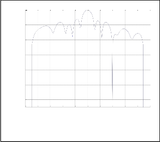
SNR of 10dB.
0
-20
-40
-60
0
-20
-40
-60
-80
-100
-120
-100 -80 -60 -40 -20 0 20 40 60 80 100 theta(degré)
Fig 5. Beam pattern of API algorithm and interference rejection at - 40° and -20°.
According to the figure 4 and 5, we note that the rejection is done systematically in the interference direction and the null depth level is remarkably very low (<
-100 dB). The array pattern does not undergo any degradation in the useful signal direction. The maim beam peak at 0°.
In the following part of simulation, we will study the behavior of the API process in the presence of several interferences simultaneously. We use the same linear array antennas with the same input API parameters used the first case but while varying the number of elements array antennas.
In the first example, we assumed a 50 element array antenna and the interferers are located at (-50°, -40°,-30, 20°). The resultant pattern is shown in Figure 6.
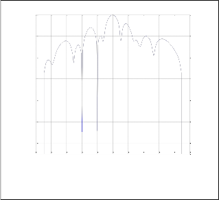
In the second example, we assumed a 10 element array antenna and seven interferers located at 40°, 50°, 60°, 10°, -
20°, -35°, and -50°. The resultant pattern is shown in Figure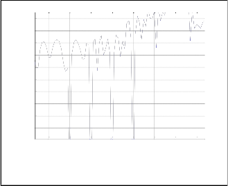
7.
-80
-25
-100
-30
-35
-120
-100 -80 -60 -40 -20 0 20 40 60 80 100 theta(degré)
-40
-45
-50
Fig 4. Beam pattern of API algorithm and interference rejection at - 40°
Figure 5 shows a plot of an M = 10 element array antenna pattern. Two interfering signals are impinging on the array from - 20° and -40° at an SNR of 10 dB.
-55
-60
-65
-70
-60 -50 -40 -30 -20 -10 0 10 theta(degré)
Figure.6: Partial Beam pattern of API algorithm and interference rejection at -50°, - 40° , -30°and -20°.
IJSER © 2012 http://www.ijser.org
International Journal of Scientific & Engineering Research, Volume 3, Issue 11, November-2012 5
ISSN 2229-5518
0
-20
-40
-60
-80
-100
-120
-100 -80 -60 -40 -20 0 20 40 60 80 100 theta(degré)
Figure.7: Beam pattern of API algorithm and interference rejection at 40°, 50°, 60°, 10°, -20°, -35°, and -50°
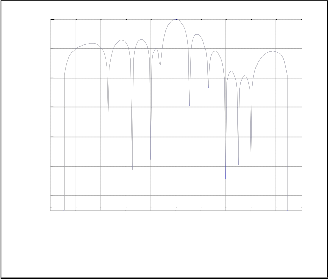
It is clear from the Figure 6 and 7, that the achieved null depths for API algorithm have very good performance (about -100dB). The interference rejection capability increases as well. We can be seen that main lobe is formed towards user at angle 0 and interfering signals are being rejected as nulls are placed towards them.
The results in this paper show that the technique of using API to control radiation pattern of array antennas, though an optimum set of array excitations to achieve a specified pattern. This technique is very effective and simple in creating nulls in the direction of the interference signals. Let us note that these interferences rejections were obtained, by optimizing one parameter of the array antennas excitation, namely the phase and by preserving fixed amplitude. These causes direct to reduce the cost of array antennas realization and its obstruction. The results obtained with this technique encourage using it in another array configuration: Non_uniform array; phased array; arbitrary spatial position; and others.
[1] M. Chryssomallis, “Smart Antennas”, IEEE Antennas and
Propagation Magazine, Vol. 42, No. 3, June 2000.
[2] C.M. Braum, R.D. Murch, Measurement of the interference rejection capability of smart antennas on mobile telephones. IEEE Vehicular Technology Conference, 1999.
[3] Carl B. Dietrich, Jr., Warren L. Stutzman, Byung-Ki Kim, and K.
Dietze, “Smart Antennas in Wireless Communications: Base- Station Diversity and Handset Beam forming”, lEEE Antennas and Propagation Magazine, Vol. 42, No. 5, October 2000.
[4] S. Choi, D.Shim, “A novel adaptive beamforming algorithm for a smart antenna system in a CDMA mobile communication environment“. IEEE Transaction Vehicular Technology, Vol. 49, No. 5, Sept. 2000.
[5] H. Lehnean. “An overview of smart antenna technology for mobile communications system”. IEEE Communications Surveys, Vol.2, No.4, 1999.
[6] X. Song, J. Wang and X. Niu. “Robust Adaptive Beamforming Algorithm Based on Neural Network”, Proceedings of the IEEE International Conference on Automation and Logistics, pp. 1844-
1849, Sep. 2008.
[7] O. Kaid Omar1, F. Debbat, and A. Boudghene Stambouli. “Null
steering beamformer using hybrid algorithm based on honey bees
mating optimisation and Tabu search in adaptive antenna
array.”Progress In Electromagnetics Research C, Vol. 32, 65{80,
2012
[8] L.C. Godara, “Application of Antenna Arrays to Mobile Communications Part I: Performance Improvement, Feasibility, and System Considerations“, Proc. of the IEEE, Vol. 85, No. 7, pp. 1029-1060, 1997.
[9] Lal C. Godara, “Application of antenna arrays to mobile communications, partП: beam-forming and direction-of-arrival considerations“, Proceeding of the IEEE, Vol. 85, No. 8, pp.1195-1234, August 1997.
[10] S. Bellofiore, Consfan fine A. Balanis, Jeffrey Foufz, and Andreas S. Spanias, “Smart-Antenna Systems for Mobile Communication Networks Part I: Overview and Antenna Design“, IEEE Antenna’s and Propagation Magazine, Vol. 44, No.
3, June 2002.
[11] Y.C. Chung, R..L Haupt, “Amplitude and phase adaptive nulling with a genetic algorithm. “ Journal of Electromagnetic Waves and Applications, Vol. 14, pp.631–649, 2000.
[12] D.W Boeringer,. and D.H. Werner, “Particle swarm optimization
versus genetic algorithms for phased array synthesis,” IEEE
Transactions on Antennas and Propagation, Vol. 52, No. 3, 771–
779, March 2004.
[13] M. Mouhamadou and P. Vaudon , “Smart antenna array patterns synthesis: null steering and multi_user beamforming by phase control“. Progress In Electromagnetics Research, PIER 60, 95–106,
2006.
[14] S. Aupetit, N. Monmarché et M. Slimane. “Apprentissage des modèles de markov cachés par l’algorithme API“. Fourmis Artificielles, des bases de l’optimisation aux applications industrielles, volume 1, Traité IC2. Hermès-Lavoisier, 2009.
[15] N. Monmarche, G, Venturini, M, Slimane. “On how Pachycondyla apicalis ants suggest a new search algorithm”. Future Generation Computer Systems 16, 937- 946, 2000.