International Journal of Scientific & Engineering Research, Volume 6, Issue 3, March-2015 54
ISSN 2229-5518
Pyrometallurgical Extraction of Tin Metal from the
Egyptian Cassiterite Concentrate
A. B. El Deeb1, I. M. Morsi 2, A. A. Atlam1, A. A. Omar1, W. M. Fathy1
(1) Al Azhar University, Faculty of Engineering, Mining and Petroleum Engineering Department. (2) Central Metallurgical Research and Development Institute (CMRDI), Egypt.
Abstract— This study aims to investigate the Pyrometallurgical extraction of tin metal from the Egyptian cassiterite concentrate. The carbothermic reduction of cassiterite concentrate by char coal in the NaR2RCOR3R - NaNOR3R molten salt system was studied at the temperature range 850 -1000•C. The results showed that more than 95% of tin was successfully extracted at smelting temperature 1000 •C and after 60 mint. smelting time. The kinetics of reaction was found to follow the chemical reaction model. The activation energy was calculated 106
KJ/mol. After purification process the tin produced had a purity of 99.6 %.
Index Terms— Carbothermic reduction, Cassiterite, kinetics, alkaline molten salt.
1 INTRODUCTION
—————————— ——————————
in presently find extensive uses in industrial and domestic applications. It has been used extensively for soldering, corrosion prevention and food packaging. Tin is found in Egypt as cassiterite mineral and the main tin bearing deposits occur in the central part of the Eastern Desert of Egypt. [1] There are many industrial techniques for tin extraction from its ores depending on the type of the ore itself, oxidic or sul- fide. Each type of the ore should be treated by the suitable
technique according to its chemical composition. [2,6]
————————————————
*A. B. El Deeb is currently pursuing masters degree program in Mining and Petroleum Engineering, Faculty of Engineering, Al Azhar University, Egypt. He completed his under graduate degree in Faculty of Engineering, Al Azhar
University, Egypt in the year 2010. His area of interest is Extractive Metallurgy
and Materials Science Engineering. E-mail: engbasuony87@yahoo.com
*I. M. Morsi, is currently working as professor in Central Metallurgical Re- search and Development Institute (CMRDI), Egypt. He has published 60 jour- nals and 10 conferences.H is area of Interest is Extractive Metallurgy Engineer- ing.
Email: immorsi@yahoo.com
*A. A. Atlam, is currently working as professor in Department of Mining and Petroleum, Faculty of Engineering, Al Azhar University, Egypt. He has pub- lished 50 journals and 20 conferences. His area of interest is Extractive Metal- lurgy and Materials Science Engineering.
Email: ahmed atlam_azhar@yahoo.com
*A. A. Omar, is currently working as professor in Department of Mining and Petroleum, Faculty of Engineering, Al Azhar University, Egypt. He has pub- lished 35 journals and 18 conferences. His area of interest is Extractive Metal- lurgy and Materials science Engineering.
Email: prof.dr.latif@gmail.com
*W. M. Fathy, is currently working as Phd.lectur in Department of Mining and Petroleum, Faculty of Engineering, Al Azhar University, Egypt. He has pub- lished 1 journals and 1 conference. His area of interest is Extractive Metallur- gy and Mineral Processing Engineering.
Email: waelfathy850@yahoo.com
Tin is extracted from oxidic ores usually by reduction smelting of the ore at high temperature (›1200 •C) in the presence of suitable fluxing agent silica or lime depending on the type and quality of the gangue material present in the ore. [3]
The principal difficulty in the Pyrometallurgical technique for gaining tin metal is the separation of tin from iron due to the high temperature of smelting. The smelting conditions should be such that the tin oxide is reduced to the metallic state while iron oxide is reduced to lower oxide (the ferrous oxide) and passes into the slag. Besides that the reduction of some iron oxide is further facilitated if the formation of FeSn and FeSnR2R are formed. [7] Also it was found that the reduction of tin and iron oxides depends on the acidity of the slags. In case of acid slags the activity of tin and iron oxides are lower than that of basic slags. An addition of lime to the slag enhances the reduc- tion process. [8,10] The admixtures of KR2RCOR3R, SiOR2R, ALR2ROR3R, CaO and tin metal all accelerate the reduction of cassiterite by graphite. [10]
The Pyrometallurgical technique requires therefore the pres- ence of high temperature silicate fluxes working at high tem- perature and needs a long reaction times due to the sluggish reaction rate between solid tin oxide and carbon. Also in this process fairly large quantity of tin oxides fails to be reduced to metallic form instead of this they combine with silica and goes into the slag. [4] To overcome the reduction of iron oxide to metallic state, smelting has to be conducted in moderately re- ducing atmosphere and at low temperature. [2] One very promising direction is using alkaline molten salts as media for the reduction of metallic oxides. Such melts fully correspond
to the requirements of the medium in which the reactions of
IJSER © 2015 http://www.ijser.org
International Journal of Scientific & Engineering Research, Volume 6, Issue 3, March-2015 55
ISSN 2229-5518
reduction of tin oxides can proceed. Alkaline molten salt pos- sess high dissolving ability with respect to starting substances. Also they provide high rate of reduction reaction and can be carried out at low temperature. [5, 6]
The carbothermic reduction of the cassiterite concentrate in the presence of sodium carbonate and sodium nitrate ten salt system was investigated at various conditions. It was suggested that the intermediate sodium stannate compound was formed during the interaction of cassiterite with this type of melt. This compound is mainly reduced by gaseous CO in the liquid melt with a high rate, thereby providing high recov- ery of tin from the cassiterite concentrate into the crude alloy. [11]
In this paper, the kinetics of extraction process of Tin metal from Egyptian cassiterite concentrate using the alkaline mol- ten salts as fluxing agents as well as the mechanism of reduc- tion process were investigated. The parameters studied are Carbon stoichiometry, ratio of Sodium carbonate, Sodium ni- trate added, temperature and time of reduction.
2 MATERIALS AND METHOD
2.1 Raw Materials
The cassiterite concentrate sample weighing about 10 kg (-
2mm size) was obtained from Abo Dabbab mining site in the Eastern Desert of Egypt. This sample was mixed thoroughly then ground in Bico mill to be passed through a sieve of -
63µm size. Coning and quartering were done to take a repre- sentative sample weighing about 200 gm. This representative sample was used for performing complete physicochemical analysis using X-Ray Fluorescence Spectrometry (XRF) and mineralogical analysis using X-Ray Diffraction analysis (XRD). Other materials used were Char coal; sodium carbonate and sodium nitrate are of chemically pure grade.
2.2 Methods
2.2.1 Smelting Process
Each run of the smelting process was carried out on batches containing 50 gm. of the concentrate  in addition to char coal as reductant, sodium carbonate and sodium nitrate as fluxing agents. The required weight of reactants to the desired propor- tions were weighed then mixed thoroughly in fireclay scorifi- ers and finally the charge was transferred to a 30 cm3 volume fireclay crucible. A Muffle Furnace of maximum temperature
1200•C was preheated to the required temperature (850 -
1000•C) then the crucible was inserted into the furnace. After completing the reduction reaction for each run, the crucible
was removed and tin metal was poured into steel mould and the slag was collected. The extracted tin metal and recovered slag were then weighed and analyzed.
2.2.2. Methods of Analysis
The grade of the recovered tin was determined by chemical analysis using volumetric titration method using standard potassium iodate solution. The slag was analyzed chemically using (XRF). Mineralogical analysis was conducted by (XRD) and Scanning Electron Microscopy (SEM - EDX) to examine the resulting phases. The percent yield of tin was then calcu- lated using the formula (R= Cc/Ff*100) where R is the percent yield of tin metal, C is the weight of tin metal produced, c is the assay of tin metal produced, F is the weight of cassiterite concentrate in the charge and f is the assay of tin in the cassit- erite concentrate.
2.2.3 Purification of Crude Tin Metal
The crude tin metal was refined with boiling process followed by Liquation. In the boiling process, the tin was melted in the crucible at 300 •C then agitated with poles of green wood. The green wood should be moistening to produce steam along with the mechanical stirring of the poles. Most of the remain- ing impurities are floated on the surface to form scum, which were then removed and tin metal was poured into the steel mould. Based on the difference in melting points and the dif- ference in specific gravity of tin alloy components, the liqua- tion refining was carried out. In Liquation process the pro- duced metal from boiling step was put on perforated funnel which was put on a crucible and then placed on the furnace adjusted at 231•C. The melted tin runs down and was collected in the crucible, while the other materials remain above as sol- ids. The high purity tin metal was then poured into the steel mould.
3 RESULTS AND DISCUSSION
3.1 Physicochemical Analysis of Cassiterite Concentrate
The mineralogical analysis of the concentrate sample using XRD in Fig. 1 revealed that the sample is composed mainly of the following minerals as shown in Table 1.
TABLE 1
MINERALOGICAL ANALYSIS OF ABU DABBAB CASSITERITE CON- CENTRATE SAMPLE.
IJSER © 2015 http://www.ijser.org
International Journal of Scientific & Engineering Research, Volume 6, Issue 3, March-2015 56
ISSN 2229-5518
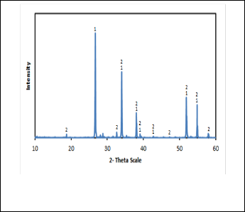
TABLE 2
CHEMICAL ANALYSIS OF ABU DABBAB CASSITERITE CON- CENTRATE.
Fig. 1. XRD pattern of cassiterite concentrate
(1) Cassiterite mineral and (2) Clinochlore mineral.
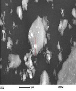
Petrographic analysis of concentrate sample in Fig. 2 revealed that the sample composed of cassiterite phase as major miner- al with minute amount of hematite mineral scattered between cassiterite crystals. Gangue minerals occur mainly as irregular grains and veinlet's of cutting across cassiterite grains com- posed of Clinochlore mineral.
The charcoal used was analyzed chemically and it was found that it has the following chemical composition as shown in
Table 3.
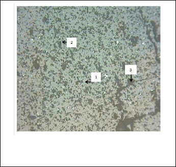
TABLE 3
THE CHEMICAL COMPOSITION OF CHARCOAL USED.
Constituent | Moisture content | Volatile matter content | Ash content | Fixed carbon content |
Wt. | 10 | 13 | 4 | 73 |
3. 2 Factors Effecting the Smelting of Cassiterite Con- centrate
Fig. 2. Micrograph of the mineral phases present in the cassiterite concentrate at X 200 (1) Cassiterite, (2) Hematite and
(3) Clinochlore mineral.
The chemical analysis of the concentrate sample using (XRF) analysis revealed that the sample composed of thirteen ele- ments present in the concentrate. Tin is the major element, while silicon, titanium, iron, aluminum, magnesium are pre- sent as minor constituents. The remaining elements existed as traces as shown in Table 2.
3.2.1 Carbon Stoichiometry
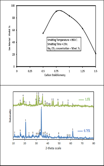
The effect of carbon stoichiometry on the tin yield was carried out by varying the carbon stoichiometry from 0.5X to 1.5X where X is the carbon stoichiometry calculated on the basis of the following equation

SnO2 (s) + 2C (s) Sn (l) + 2CO (g) ……… (1)
Fig. 3 shows the variation of the tin yield as a function of vari- ation of carbon stoichiometry in presence of 50 Wt. % sodium carbonate. It is obvious that increasing the molar ratio of car- bon to the tin oxide improves the solid state reduction by in-
creasing the tin yield from 55% to about 91% by increasing the
IJSER © 2015 http://www.ijser.org
International Journal of Scientific & Engineering Research, Volume 6, Issue 3, March-2015 57
ISSN 2229-5518
molar ratio from 0.5X to 0.75X respectively after which it de- creases to 21% at 1.5X. The increasing effect is expected since the increasing of carbon to tin dioxide ratio can improve the contact condition between tin oxide and carbon so that the carbon can be used more efficiently. However when this ratio is higher than 0.75X the rate of reduction was slowed down to give low tin yield which is against what is expected. The con- tent of 0.75X was recommended therefore as the best optimum condition. The obtained XRD patterns of the produced slags containing two different carbon stoichiometries 0.75X and 1.5X are shown in Fig. 4. The phases present in these slags are summarized in Table 4. It is clear that these two slags have some common phases presented with different intensities in- cluding sodium aluminum silicate and sodium salts of alumi-
num and titanium. The 0.75X slag is free from the presence of
sodium salts of tin (sodium stannate) and lower oxides of tin (SnO) but traces of tin metal are present. On contrasting to that these phases were confirmed in the 1.5X slag with high inten- sities. It is known that the reduction of cassiterite proceeds through a series of redox process and it can be expressed by the summary equations [11]

2SnOR2R(s) + 3C (s) 2Sn (l) + 2CO (g) + COR2 R(g) ….. (2)
∆G R1000R∙RC = - 210KJ

SnOR2R (s) + 2CO (g) Sn (l) + 2COR2R (g) ……. (3) C (s) + COR2R (g)  2C0 (g) …….. (4)
The equilibrium of the reaction is shifted towards the for- mation of target product (tin) and this tendency will be en- hanced by removing the gaseous reaction products CO and COR2R. In our case the carbothermic reduction process is carried out at low melting point alkaline salts, indeed the viscosity of the melted flux will play a role for escaping off gaseous reac- tion products as well as the proceeding of Boudouard reaction Equation (4). The presence of excess carbon in this melt may increase its viscosity which prevents the generation of reduc- ing gas CO as well as the escaping of reduction products COR2R at the contact point of cassiterite particles and carbon grains. It is obvious from Table 4 that at high carbon content (1.5X) there is amount of tin present as sodium stannate , SnO and tin resulting in the low yield of tin metal as a result of incom- plete reduction of these tin salts. In turn at low carbon content (0.75X) there is a complete reduction of tin oxides salts by CO represented in the high yield of tin metal and the absence of sodium stannate phase. This means that at low carbon content the slag may have high fluidity which may cause increasing in
the yield of tin metal.
Fig. 3. Effect of carbon stoichiometry on the percent yield of tin metal
Fig. 4. XRD patterns of produced slag with different carbon stoichi- ometry.
3.2 Sodium Carbonate Ratio
TABLE 4
THE PHASES PRESENT IN SLAG W ITH DIFFERENT CARBON STOI-
CHIOMETRY
IJSER © 2015 http://www.ijser.org
International Journal of Scientific & Engineering Research, Volume 6, Issue 3, March-2015 58
ISSN 2229-5518
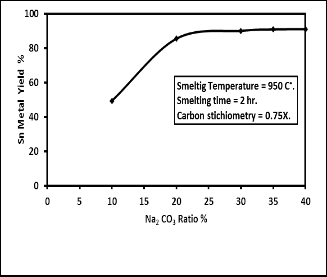
The effect of ratio of sodium carbonate added which acts as fluxing material, on the yield of tin metal was investigated by varying its percentage from 10 to 40% by weight of concen- trate. Fig. 5 reveals that tin metal yield increased with increas- ing the amount of sodium carbonate added reaching the max- imum value of about 85 % at sodium carbonate ratio 20% after which the tin yield is nearly the same. Therefore the ratio of
20% sodium carbonate added is considered to be the most fa- vorable condition for the maximum yield of tin metal. Fig. 5 shows that using the alkaline flux sodium carbonate gives bet- ter yield at lower smelting temperature and time than acidic flux. This can be seen from the results obtained by [8] that used silicon dioxide as flux and [9] that used silicon dioxide
and calcium oxide as fluxing materials.
The XRD patterns of the produced slag having two different sodium carbonate ratios 10% and 35% are shown in Fig. 6. The phases present in these slags are summarized in Table 5. It is obvious that the two slags contain sodium aluminum silicates as a main phase which has high intensity for the slag contain- ing 35% sodium carbonate. Besides that these slags showed the presence of high intensity lines of sodium salts of alumi- nates, iron titanates, titanates and traces of tin metal. On other hand the 10% sodium carbonate slag is rich in sodium salts of tin (stannate), tin oxides (SnO2 , Sn3 O4 and SnO), tin metal and sodium titanates.
It can be seen that at high sodium carbonate content (35%) there is nearly complete reduction of tin oxide indicating that high sodium carbonate content may increase the slag fluidity by forming the much fusible compounds as a result of reaction between sodium oxide and the oxides of the gang mineral (clinochlore). This case in turn increases the reduction of tin salts by CO and enhances the escaping of reaction product CO2 . High slag fluidity also facilitates the separation of tin metal formed from slag. Also high sodium carbonate content is sufficient to react with other elements in the concentrate and dissolved them in the slag as sodium ferrates, titanates, alu- minates and silicates. In turn at low sodium carbonate content (10%) there is much chance for incomplete reduction of tin salts where high content of sodium stannate exists in the slag besides the presence of tin dioxide, tin monoxide and Sn3 O4 phases.
The low content of sodium carbonate may cause an increase in the slag viscosity and impedes the separation between the metal and the slag which in turn reduced the yield of tin met-
al.
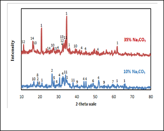
Fig. 5. Effect of Sodium carbonates concentration on the percent yield of tin metal.
Fig. 6. XRD patterns of produced slag containing different sodi- um carbonate ratios
TABLE 5
THE PHASES PRESENT IN SLAG CONTAINING DIFFERENT SODIUM CARBONATE RATIOS
IJSER © 2015 http://www.ijser.org
International Journal of Scientific & Engineering Research, Volume 6, Issue 3, March-2015 59
ISSN 2229-5518
3.3 Sodium Nitrate Ratio
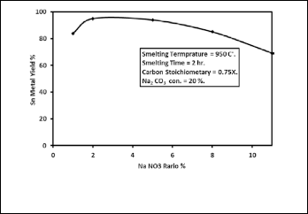
The effect of Sodium nitrate addition which acts as an oxidiz- ing agent on the yield of tin metal from the concentrate was determined by varying the ratio of the Sodium nitrate added from 1 to 11% by weight of concentrate in the presence of 20 wt. % sodium carbonate. Fig. 7 shows the effect of sodium nitrate addition on the percent yield of tin metal. It reveals that the maximum yield of tin metal was achieved at sodium nitrate weight ratio of 2%. Also it is noticed that the tin metal yield increases from 84% to 95% when the ratio of sodium ni- trate increased from 1 to 2% but when the ratio of sodium ni- trate added increased from 2% to 11% the yield of tin metal decreased from 95% to 69%. Therefore, the ratio of 2% of sodi- um nitrate was taken as the optimum value. The XRD patterns of the produced slag for two different sodium nitrate ratios,
2% and 11% are shown in Fig. 8. Table 6 summarizes the phas-
es present in the two slags. The common phases present in these two slags are sodium aluminum silicate, SnR3ROR4R, sodium stannate and sodium titanates. While sodium aluminum sili- cate has high intensity in 11% slag, it is higher in 2% slag. Also
11% slag contains SnR3ROR4R, sodium ferrites, sodium silicates and sodium iron silicate phases. It can be seen that at low sodium
nitrate content (2 %) there is more reduction of tin salts repre- sented in the high yield of tin metal. When Sodium nitrate decomposes, the oxygen evolved and NaNOR2R is formed which in turn decomposes to form NaR2RO. In this case, the evolved oxygen may activate the combustion of coal and promoting Boudouard reaction which increases the reduction potential to yield more tin metal. In the case of high sodium nitrate con- tent (11%) there is incomplete reduction of tin oxides as well as sodium stannate, SnR3ROR4R and SnO. The presence of excess sodium nitrate in the system may provide oxidation of some of the produced tin to its oxides and stannate phases again which lowers tin metal yield percentage. Sodium nitrate can also act as an oxidizing agent to keep the base metals present in the slag in their oxidized state preventing them from being reduced and entering the metal phase.
Fig. 7. The effect of Sodium nitrate addition on the percent yield of tin metal.
Fig. 8. XRD patterns of produced slag containing different sodium nitrate ratios.
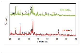
TABLE 6
THE PHASES PRESENT IN SLAG CONTAINING DIFFERENT SODIUM
NITRATE RATIOS
No | phase | 2 % | 11 % |
1 | NaR4RAlR2RSiR2ROR9 | + + + + | + |
2 | Na FeOR2 | - | + |
3 | SnR3ROR4 | + | + |
4 | NaR2RTiSiR4R OR11 | + | - |
5 | SnO | - | + |
6 | Sn | - | + |
7 | NaR2RO 2SnOR2 | + | + + |
8 | NaR2RTiR3ROR11 | + | + |
9 | NaR6R SiR2R OR7R .11 HR2RO | - | + |
10 | NaFeSiR2ROR6 | - | + |
3.4 Smelting Temperature
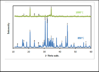
Fig. 9 describes the effect of reduction temperature on the per- cent yield of tin metal for batches containing 20 wt. % sodium carbonate and 2 wt. % sodium nitrate. This was determined by varying the reduction temperature from 850•C to 1050•C for constant reduction period 120 min. As shown in Fig. 9 reduc- tion temperature has a significant positive impact on the re- duction of stannic oxide in presence of sodium carbonate and sodium nitrate. It reveals that tin metal yield increases with increasing the temperature of reduction. The percent yield of tin metal increases sharply from 64 % to 97 % as the reduction temperature increased from 850 to 1000•C. When the reduction temperature further increases to 1050 °C the percent yield of tin metal is nearly constant. Therefore, the reduction tempera- ture of 1000•C has been preferred as the optimum value. The XRD patterns of the product slag for two different smelting temperatures 850•C and 1000•C are shown in Fig. 10. The re- sults obtained are given in Table 7. This indicates that at low temperature there are losses of tin in the form of tin oxides, tin metal and sodium stannate. The lower temperature is there-
fore, insufficient to reduce the tin oxides completely. In turn at
IJSER © 2015 http://www.ijser.org
International Journal of Scientific & Engineering Research, Volume 6, Issue 3, March-2015 60
ISSN 2229-5518
high temperature almost all tin oxides completely reduced to tin metal represented in the high yield of tin metal. Sodium aluminum silicates and sodium stannate phases are still com- mon phases in the produced slags at 850 and 1000•C smelting temperatures. However the former phase exists in high inten- sity in 1000•C slag, on contrasting to that sodium stannate is in excess at 850•C besides the presence of tin oxides (SnO and
Sn3 O4 ) and tin metal as main phases in this slag.
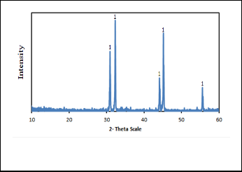
indicates that it consists mainly of 100% tin lines as shown in Fig. 11. When this metal was refined using boiling process, it gives tin with purity (99.4%) and which given by Liquation process was (99.6%).
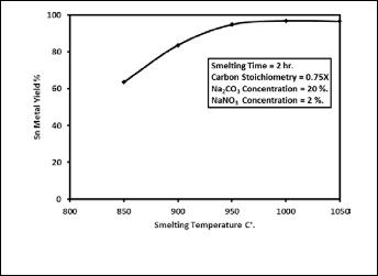
Fig. 11. The XRD pattern of the produced tin metal at optimum con- dition.
Fig. 9. Effect of smelting temperature on the percent yield of tin metal.
4 Kinetics of Cassiterite Smelting Process
4.1 Smelting Isotherms
The smelting of cassiterite concentrate was carried out at op- timum conditions in the presence of 0.75X carbon stoichiome- try, 20 wt. % sodium carbonate and 2 wt. % sodium nitrate at temperature range 850 to 1000•C. Fig. 12 shows the reduction isotherms where the yield increases gradually as the smelting temperatures and times increased. The maximum yield was
obtained 95% at 1000•C after 60 min. smelting period.

Fig. 10. XRD patterns of produced slag for two different smelting temperatures.
The XRD pattern of produced tin metal at optimum conditions
TABLE 7
THE PHASES PRESENT IN SLAG FOR TW O DIFFERENT SMELTING TEMPERATURES
Fig. 12. Plot of the percent yield of tin metal versus time of reduction at different smelting temperature.
The XRD patterns of the slags produced at 1000•C after differ- ent smelting times 40, 80 and 120 min. are shown in Fig. 13.
IJSER © 2015 http://www.ijser.org
International Journal of Scientific & Engineering Research, Volume 6, Issue 3, March-2015 61
ISSN 2229-5518
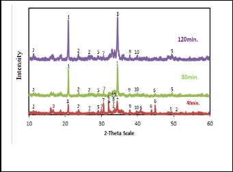
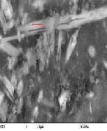
The phases obtained in the three slags are given in Table 8. The 120 min. slag composed mainly of sodium aluminum sili- cates phase with sodium silicates, ferrate and titanates and traces of SnO and Sn3 O4 . The 40 min. slag contains beside these phases, the intermediates of tin compounds, stannate, SnO2 , Sn3 O4 , SnO and tin metal. The 80 min. slag has the same intermediate phases but they are present as traces. From these analysis it appears that at lower smelting time there are loses of tin in the form of tin oxides, tin metal and sodium stannate indicating that this time is insufficient to reduce all tin oxides. In turn at higher smelting time most all tin oxides were re- duced to tin metal represented in the high yield of tin metal. SEM - EDX of slag obtained at optimum condition and re- duced at 1000•C for120 min. is illustrated in Fig. 14 for differ- ent locations in this slag showing its chemical composition for the main phases present. These results as a mean confirm that these slags may compose essentially from sodium aluminum silicates, sodium stannate, sodium ferrate and sodium titan- ates.
Fig. 13. XRD patterns of produced slags for different smelting times at 1000•C.
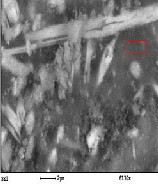
TABLE 8
THE PHASES CONTAINED IN SLAGS PRODUCED AFTER DIFFER- ENT SMELTING TIMES AT 1000•C.
Fig. 14. SEM- EDX for slag at optimum condition for sample reduced at 1000•C. for 120 min.
IJSER © 2015 http://www.ijser.org
International Journal of Scientific & Engineering Research, Volume 6, Issue 3, March-2015 62
ISSN 2229-5518
4.2 Application of Solid State Reduction Models
Some solid state reaction models were investigated to find which kinetic equation can fit the reaction isotherms obtained in Fig. 12. It was found that the model postulated for chemical reaction controlling process at phase boundaries [diminishing area equation (1)]. [12]
[1 – (1-X) 1/3] = K t ……………. (1)
Where [X] is the fraction reacted, [K] is the reaction rate con- stant (min-1) and [t] is the reaction time is the most applicable model for all reduction isotherms up to 85% yield. Fig. 15 shows the result of plotting [1-(1-X) 1/3] as a function of time at different smelting temperatures. The mean values of the reac- tion rate constants K were determined from the slopes of these straight lines.

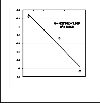
The logarithmic values of these reaction rate constants were plotted against the reciprocal of the absolute reduction temper- ature according to the Arrhenius equation Fig. 16. The apparent activation energy was calculated from the slope of straight line obtained to be 106kJ/mole. This value is nearly similar to that calculated by some authors [10,13] and some what lower than that obtained previously by others [14].
Fig. 15. Application of chemical reaction model
[Kt = 1- (1-X) 1/3 ]
Activation
9nergy =
106KJ/mol
0.00078 0.0008 0.00082 0.00084 0.00086 0.00088 0.0009
1 / TK-1
Fig. 16. Application of Arrhenius plot.
4.3 Mechanism of Cassiterite Smelting Process in the
Presence of Alkaline Molten Salts
The following facts can be deduced from the present investi- gation.
1- The reduction of cassiterite is chemically controlled solid state reaction.
2- The presence of some relics of metallic tin in the produced slags.
3- The produced slags consist mainly of sodium aluminum silicate phases with different forms of sodium titanates, fer- rates, aluminates and silicates.
4- The presence of sodium stannate phases in the produced slags is related to low yield of metallic tin.
5- Presence of relics of SnOR2R and lower valence tin oxides SnO
and SnR3ROR4R in the produced slags.
6- The addition of sodium carbonate enhanced the smelting process of cassiterite concentrate.
7- The addition of sodium nitrate in minute amount enhanced also the smelting process of cassiterite concentrate.
Depending on these facts, the mechanism of smelting process of cassiterite concentrate in the presence of liquid alkaline
fluxing agents may be visualized as follows:
IJSER © 2015 http://www.ijser.org
International Journal of Scientific & Engineering Research, Volume 6, Issue 3, March-2015 63
ISSN 2229-5518
4.3.1 Slag Forming Reactions
gests that there are probably three phase boundaries formed
between the different reacted phases SnOR2R/ SnR3ROR4R/ SnO/
The alkali fluxing agent sodium oxide is reacted directly with
SnR(l)R
from which one of the first two phase boundaries is prob-
gangue materials (here clinochlore) to form low melting point
salts, silicates, aluminum silicates, titanates aluminates and
ably the rate controlling step. According to this visualized mechanism, the formation of sodium stannate clearly retards
ferrates which their formulue depends on the ratio of reacted
the reduction process by capturing some of SnOR2R
in the form
compounds adjacent to each other's and the temperature of
the smelting process. Also some of sodium oxide reacts with tin dioxide to form sodium stannate phases.
4.3.2 Cassiterite Reduction Reactions
The presence of lower valence oxides of tin in the produced slags confirm that the SnO2 may be reduced to tin metal via passing by intermediate phases according to the following reactions:-
1- Initiation reaction [direct reaction]: This reaction is carried out by direct reduction of SnO2 with carbon at points of con- tacts between the cassiterite grains and charcoal particles. The reaction is represented by
of stannate phase lowering the metallic yield of tin which is contrary to what is reported previously [11].
Sodium carbonate addition also seems to play an important role, when its concentration increases it become a source of carbon dioxide gas in the system which increase the computa- tion of charcoal according reaction (6) enhancing therefore the reduction process through the formation of CO gas.
Addition of sodium nitrate in minute amount indeed acceler- ates the oxidation of charcoal producing excess of carbon monoxide to increase the reduction potential of the system which is translated in increasing the yield of tin. At high con- centration of sodium nitrate, the released oxygen from its dis-
sociation is too much which lead to oxidizing the reduced tin
3SnO2 (s) + 2C (s)  Sn3 O4 (s) + 2CO (g) …… (1)
to SnOR2R
or its lower oxides. This leads to the loss of tin in the
form of sodium stannate and retardation of reduction process.
2- Main reduction reactions [Indirect reactions]: These reac-
It should be mentioned here that the oxidation of Sn O to
R3R
R4R
tions proceed by using the produced carbon monoxide gas
form SnOR2R
which is the reverse of reaction (2) was reported by
according to the following equations:
many authors [15] to be occurred at temperature higher than
• •

3SnO2 (s) + 2CO (g)  Sn3 O4 (s) + 2CO2 (g) …… (2) Sn3 O4 (s) + CO (g) 3SnO (s) + CO2 (g) …… (3)
∑ [2+3] gives
3SnO2 (s) + 3CO (g)  3SnO (s) + 3CO2 (g) …… (4) Or

SnO2 (s) + CO (g) SnO (s) + C02 (g) ……… (4)
∆G 1200k = -5.4 kJmol-1
SnO (s) + CO (g)  Sn (l) + C02 (g) ……… (5)
∆G = -16.6 kJmol-1

C (s) + COR2R (g) 2C0 (g) …… (6)
∆G R1200kR = -39.6 kJmol
∑ [4+5+6] gives
SnOR2R (s) + C (s)  Sn (l) + COR2R (g) ……… (7)
∆G R1200kR = -61.6 kJmol
The reaction (6) occurs as parallel to other reactions, where the carbon oxidation reaction takes place to produce reducing gas carbon monoxide. Also the calculated Gibbs free energy of reaction (4) shows that this reaction is probably the rate con- trolling step where its value (-5.4 kJmol-1) is somewhat less
negative than the other reactions (5, 6). This mechanism sug-
500 C up to 900 C.
CONCLUSION
1- The carbothermic reduction of cassiterite concentrate in the melt of NaR2RCOR3R- NaNOR3R salt system provides a yield of more than 95% tin metal by using carbon stoichiometry of 0.75X and presence of 20 wt. % sodium carbonate 2 wt. % sodium nitrate and reduced at 1000•C for 60 min.
2- Smelting temperature has noticeable effect on the reaction rate. An activation energy of 106 KJ/mol was calculated for the reduction of cassiterite concentrate.
3- The purity of refined tin after boiling process was (99.4 %)
and that of Liquation process was (99.6 %).
4- Basic (alkaline) fluxes gives better recovery, high purity tin metal by using lower smelting temperature and time.
5- Lower tin oxides are formed during cassiterite reduction confirming that the SnOR2R may be reduced to tin metal via passing by intermediate phases SnR3ROR4R and SnO.
6- The formation of sodium stannate retards the reduction process leading to lowering the yield of tin metal.
IJSER © 2015 http://www.ijser.org
International Journal of Scientific & Engineering Research, Volume 6, Issue 3, March-2015 64
ISSN 2229-5518
7- Addition of sodium carbonate and minute amount of sodi- um nitrate enhance the reduction process of cassiterite concen- trate.
REFERENCE
[1] A. H. Sabet et al, “Tin- Tungsten mineralization in the Cen- tral Eastern Desert of Egypt,” Ann. Geol. Surv. Egypt. No 3, pp. 75-86, 1973.
[2] F. Habashi, “Handbook of Extractive Metallurgy,” vol. 2, New York, pp. 683-714, 1997.
[3] N. N. Murach and N. N. Sevryukov, “Metallurgy of Tin,” Moscow, 1964.
[4] P. A. Wright, “Extractive Metallurgy of Tin,” Elsevier pub. Co., London, 1982.
[5] A. S. Lebedev, V. E. Dyakov and A. N. Terebenin, “Com- plex Metallurgy of Tin,” Novosibirsk, 2004.
[6] V. V. Gostishchev, Ri, E. Kh, S. V. Dorofeev, V. G. Kom- kov, and Ri Khosen, Patent 2333268, 2008.
[7] R. Smith, “An analysis of the process For Smelting Tin,” Mining History: The Bulletin of the Peak District Mines His- torical Society, Vol.13, No.2 pp. 91-99, winter, 1996.
[8] A. A. Omar, “Pyro metallurgical Treatment of Egyptian Cassiterite Concentrate,” Bulletin Tims, Vol. 67, no. January, pp. 26 –36, 1996.
[9] I. M. Morsi, F.A.H. Abdalla, K.A. El-Barawy, and S. Z. El- Tawil, “Tin recovery from local Cassiterite concentrate,” Mod- elling, measurement and control, C, AMSE press vol. 36, no.2, pp. 13-28, 1993.
[10] J. S. J. Van Deventer, “The Effect of Admixtures on the
Reduction of Cassiterite by Graphite,” Thermochemical Acta,
124 pp. 109-118, 1988.
[11] V. G. Komkov, V. V. Gostishchev, and E. K. Ri, “Physico- chemical aspects of carbothermic reduction of cassiterite in the ionic melt,” Russ. J. Non-Ferrous Met., vol. 50, no. 6, pp. 596–
599, Jan. 2010.
[12] J. Szekely, J. W. Evans and H. Y. Sohn, “Gas – Solid reac- tions,”, Academic press, N.Y. pp. 75-76, 1976.
[13] A. R. Mitchell and R. H. Parker ' The reduction of SnOR2R by solid carbon' Minerals Eng., vol.1, no1, pp. 53 – 66, 1988.
[14] R. Padilia and H. Y. Sohn, “The Reduction of Stannic Ox- ide with Carbon,” Metallurgical Transaction vol. 10, pp. 109–
115, March 1979.
[15] C. J. Damaschio et al., “SnR3ROR4R single crystal Nano belts grown by carbothermal reduction process,” Journal of Crystal Growth, no 312, pp. 2881-2886, 2010.
IJSER © 2015 http://www.ijser.org