International Journal of Scientific & Engineering Research, Volume 5, Issue 3, March-2014 - 1491 - ISSN 2229-5518
Promotion of heat transfer using twisted tape to generate additional turbulent
![]()
![]()
ABSTRACT--Heat transfer enhancement techniques refer to different methods used to increase rate of heat transfer without affecting much the overall performance of the system. These techniques are used in heat exchangers. Some of the applications of heat Exchangers are-in process industries, thermal Power plants, air-conditioning equipments, refrigerators, radiators for space Vehicles, automobiles etc. These techniques broadly are of three types viz. passive, active and compound techniques. Three cases of heat transfer enhancement by turbulence promoters were adopted in order to increase the thermal performance of a double pipe heat exchanger effective length, 30 mm outer pipe diameter and inner pipe diameter (20 mm). Twisted tape of 10 mm width and
3.5, 4and 5 twist ratio were used as turbulence promoters to augment heart transfer inside the inner tube of heat exchanger at a Reynolds number range of
5000 to 35000 based on smooth tube diameter. Two new types of turbulence promoters are used to enhance heat transfer in the inner tube of the same double
pipe heat exchanger. The first was by Twisted tape of (twist ratio= 4) and 1100mm length set up on the inner tube. The second was by Twisted tape of (twist ratio= 3.5) with five hole on it and 1100mm length at the same position. The third was by Baffled Reduced W idth Twisted Tape (twist ratio= 5) with five holes, holes of diameter 6 mm were drilled at midpoint of two consecutive strips of BRWTT. W ater was used as the working fluid in the two sides. Variation in the experimental conditions was attained by changing the mass flow rates of unenhanced side and changing the inlet temperature of hot fluid. These conditions were followed in order to increase the data points in addition to observe the effect of these conditions.
—————————— ——————————
Heat exchangers are used in different processes ranging from conversion, utilization & recovery of thermal energy in various industrial, commercial & domestic applications. Some common examples include steam generation & condensation in power & cogeneration plants. Sensible heating & cooling in thermal processing of chemical, pharmaceutical & agricultural products; fluid heating in manufacturing & waste heat recovery etc. Increase in Heat exchanger’s performance can lead to more economical design of heat exchanger which can help to make energy, material & cost savings related to a heat exchange process. Enhancement techniques essentially reduce the thermal resistance in a conventional heat exchanger by promoting higher convective heat transfer coefficient with or without surface area increases. As a result, the size of a heat exchanger can be reduced, or the heat duty of an existing exchanger can be increased, or the pumping power requirements can be reduced, or the exchanger’s operating approach temperature difference can be decreased [1].Nowadays, twisted-tape inserts have widely been applied for enhancing the convective heat transfer in various industries, due to their effectiveness, low cost and easy setting up. Energy and material saving consideration, as well as economical, have led to the efforts to produce more efficient heat-exchanger equipment.
The Problem of Turbulence, Turbulent fluid flow is a complex, nonlinear multi-scale phenomenon, which poses some of the most difficult and fundamental problems in classical physics. It is also of tremendous practical importance in making predictions, for example, about heat transfer in nuclear reactors, drag in oil pipelines, the weather, and the circulation of the atmosphere and the oceans. Many generations of scientists have struggled valiantly to understand both the physical essence and the mathematical structure of turbulent fluid motion. Leonardo da Vinci in (1507) named the phenomenon observed in swirling flow "la tubolenza" [2]. The scientific study of turbulence had generally begun with the work of Osborne Reynolds in (1883). The problem that Reynolds had studied was the classic one of flow through long straight pipes of constant diameter and circular cross-section. Using his "method of color bands", he was the first person to show that, for a given fluid and pipe, the flow would be orderly (laminar) for velocities below a certain critical speed. At the critical speed, the flow abruptly became turbulent at some distances from the pipe entrance [3]. Reynolds found that the criterion for the transition from laminar to turbulent flow could be expressed in universal form in the terms of the value taken by dimensionless group:
Re =![]()
𝜌𝑑𝑣
𝜇
(1)
Where "Re" is what is now called the Reynolds number. Reynolds noted that the main motion of the flow took place in the direction of the axis of the pipe. Because of the flow fluctuations, a great amount of mixing occurred in the turbulent flow, leading to a transverse motion perpendicular to the main motion. It was discovered that the transition from laminar to turbulent flow always took place at almost exactly the same Reynolds number (Recrit. = 2300). For Re< Recrit , the flow is laminar and turbulent for Re< Recrit . It is already suspected that the critical Reynolds number will be larger if the disturbances in the incoming flow are smaller Enhancement of Heat Transfer. Here, a brief survey for the most recent works performed in the field of heat transfer enhancement in single–phase flow is included concentrating on those that depends on turbulence caused by devices or inserts installed in the flow passage which may be referred to as " turbulence promoters". Some studies, stated here, ascribe the enhancement of heat transfer to vortices or swirls generated by these devices; the present survey will include, for the reason that such phenomena may occur together with turbulence Enhancement of Heat Transfer by Turbulence Promoters. To make it easy to understand and compare the different types of turbulence promoters, a simple classification, built on the basis of similarity in configuration and the manner of work for each group, is introduced in the following sections. Twisted tapes, helical inserts and twisted angles. Twisted tape inserts cause the flow to spiral along the tube. Their potential performance is diminished because the thermal contact of the tape and the tube wall is not ideal, so they do not perform as "wall-attached roughness". They enhance the heat transfer due to the increased tangential velocity component and reduced flow cross section. Thianpong et al., in 2009 [4] investigated experimentally the friction factor and heat transfer behaviors in a dimpled tube fitted with a twisted tape swirl generator using air as working fluid in the range of Reynolds number of 12000 to 44000. They found that both heat transfer coefficient and friction factor in the dimpled tube fitted with the twisted tape, were higher than those in the dimple tube acting alone and plain tube. Silapakijwongkul [5] in this work, effect of the tapes
IJSER © 2014 http://www.ijser.org
International Journal of Scientific & Engineering Research, Volume 5, Issue 3, March-2014 - 1492 - ISSN 2229-5518
twisted in clockwise and counterclockwise arrangement (C-CC arrangement) on heat transfer and friction factor characteristics in a double pipe heat exchanger was investigated experimentally. The mean heat transfer rates obtained from using C-CC twisted-tape arrangement and original twisted-tape arrangement are found to be 219% and 204%, respectively over the plain tube.
Fluid Flow and Heat Transfer in Circular Tubes Turbulent flow is commonly utilized in practice because of the higher heat transfer coefficients that is associated with. Most correlations for the friction and heat transfer coefficients in turbulent flow are based on experimental studies because of the difficulty in dealing with turbulent flow theoretically. For smooth tubes, the friction factor in turbulent flow can be determined from the first Petukhov equation [7]
£ = (0.79𝑙𝑛𝑅𝑒 − 1.64)−2 (2)
Or from the well-known Moody diagram. The friction factor considered in Equation is the Darcy friction factor that is used to calculate the
pressure drop using the equation [8, 9].
∆p = £![]()
𝐿 ƿ
𝑑𝑖
![]()
𝑣 2
2
(3)
This is well-known as Darcy-Weisbach equation. The Nusselt number in turbulent flow is related to the friction factor through the Chilton–
Colburn analogy [10] expressed as.
Nu = 0.125 £ Re 𝑃𝑟1⁄3
(4)
With the friction factor is available, that can be used conveniently to evaluate the Nusselt number for both smooth and rough tubes. For fully developed turbulent flow in smooth tubes, a simple relation for the Nusselt number can be obtained by substituting the simple power law relation
£ = 0.184 𝑅𝑒 −2 (5)
For the friction factor into equation it gives
Nu = 0.023 𝑅𝑒 0.8 𝑃𝑟1⁄3
(0.7 ≤ Pr ≤ 160, 𝑅𝑒 ≥ 10,000 ) (6)
This is known as the Colburn equation. The accuracy of this equation can be improved by modifying it as:
Nu = 0.023 𝑅𝑒 0.8 𝑃𝑟𝑛 (7)
Where n = 0.4 for heating and 0.3 for cooling of the fluid flowing through the tube. This equation is known as the Dittus–Boelter equation,
with Properties of the fluid concerned evaluated at the bulk mean fluid temperature [11] ,Tb =(Ti -To )/2 ,When the temperature difference between the fluid and the wall is very large, a correction factor is used to account for the different viscosities near the wall and at the tube center. Sieder and Tate [12] suggested a correction factor to be used with all the equations above
ц𝑏
0.14
![]()
𝑁𝑢𝑐 = Nu � �
𝑤
(8)
Where (μb ) is evaluated at bulk mean temperature while (μw ) at the temperature of the wall. The Nusselt number relations above are fairly simple, but they may give errors as large as 25%. [13]
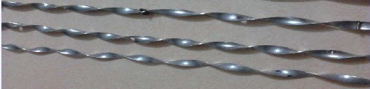
The stainless steel strip of length 110cm, width 10mm and thickness 1 mm was taken. Desired twist was obtained using a Lathe machine. One end was kept fixed on the tool post of the lathe while the other end was given a slow rotator motion by rotating the chuck side. During the whole operation the tape was kept under tension by applying a mild pressure on the tool post side to avoid its distortion. Three tapes with varying twist ratios were fabricated (y/h=3.5, y/h =4 and y/h=5) as shown in fig 1. For making baffled twisted tape (BRWTT), small cuts were made on original twisted tape & on the strips of size 16mm×10mm which were then fitted together. The distance between two consecutive baffles was kept 20cm. Baffle strips were projecting at right angles to the surface of twisted tape on each side. Holes of 6 mm diameter were drilled at midpoint of two consecutive baffles.
Fig 1 Show three type of twisted tape
Fig 2 shows the two loops System with Rig experimental setup. It is a double pipe heat exchanger consisting of a calming section, test section, rot-meters, water tank for supplying cold water & a constant temperature bath for supplying hot water heater, pump & the control system. The test section is a smooth copper tube with dimensions of 110cm length, Inner tube-18mm ID, and 20mm OD; Outer copper pipe-30mm ID, and 32 mm OD. The outer pipe is well insulated using 15mm die, Asbestos rope to reduce heat losses to the atmosphere. Two calibrated rot- meters, with the flow ranges 1 to 5 LPM and 300 to 1250 LPH, are used to measure the flow of cold water. The water 20 C temperature is pap from a cold tank. Similarly a rot-meter is provided to control the flow rate of hot water from the inlet hot water tank. Hot water flow rate is kept constant at 0.074 Kg/sec. Two pressure tapings- One just before the test section and the other just after the test section are attached to the U-tube manometer for pressure drop measurement. Mercury is used as the man metric fluid. Four RTDs measure the inlet & outlet temperature of hot water & cold water, through a multipoint digital temperature indicator.
IJSER © 2014 http://www.ijser.org

International Journal of Scientific & Engineering Research, Volume 5, Issue 3, March-2014 - 1493 - ISSN 2229-5518
Fig 2 Two loop System with Rig
4. Results and Discussion
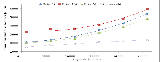
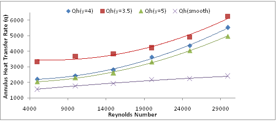
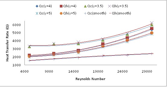
Experiments on twenty four cases of smooth and augmented tubes and annuli were carried out in order to study the effect of different types of twisted tape inserts on heat transfer and pressure drop in a double pipe heat exchanger. The primary experimental data taken are temperatures of the four inlets and outlets, pressure drop in the two sides and heat transfer rate at different experimental conditions, the Effect of Turbulence Promoters on Heat Transfer Rate and Pressure Drop. To have a general view of the effect of turbulence promoters, used in the present work, on heat transfer rate and pressure drop in the inner tube and annulus, values of heat transfer rate and pressure drop are plotted versus Reynolds number in figs. (3 through 6) for all cases
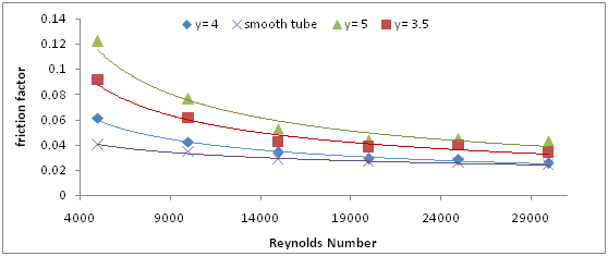
Effect of Turbulence Promoters on Friction Factor Friction factor inside the inner tube and annulus either smooth or with Twisted tape inserts , have been calculated using the experimental values of pressure drop using equation (2), plotted in fig.7 versus Reynolds number
Figure 7 shows the variation of friction factor (fa) with Reynolds Number for Smooth tube, different type of twisted tape ,Baffled Reduced width twisted tape with holes (BRWTT) for different twist ratios (y/h=3.5,4, & 5) ,As the twist ratio decreases, a higher degree of swirl is created which leads to higher pressure drop & hence higher friction factor. In case of BRWTT, a much higher friction factor is observed because of increase in degree of turbulence created by the respective tapes.
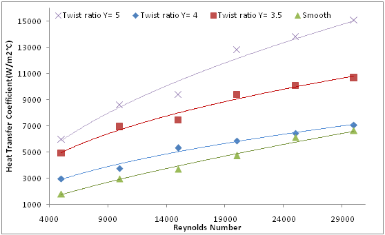
Heat Transfer Coefficient Results, the heat transfer results for smooth, TT1, TT2 & BRWTT. Fig 8 shows the variation of heat transfer coefficient (ha) with Reynolds Number for Smooth tube, Twisted tape(TT1), Twisted tape with five holes (TT2), Baffled Reduced width twisted tape with holes (BRWTT2) for different twist ratios (y/w=3.5, y/w=4, y/w=5). As the twist ratio decreases, a higher degree of swirl is created which increases turbulence & hence the heat transfer coefficient increases as the twist ratio decreases. In case of BRWTT, a much higher heat transfer coefficient is observed because of increase in degree of secondary flow created which disturbs the entire thermal boundary layer & hence the heat transfer coefficient increases as the twist ratio decreases.
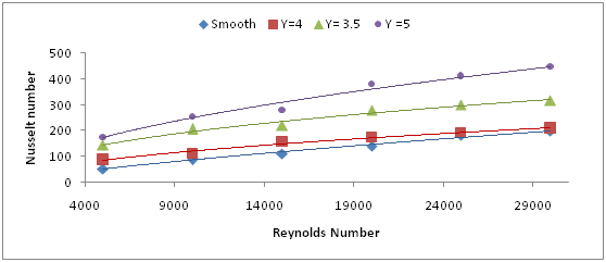
Effect of Turbulence Promoters on Heat Transfer In addition to friction factor, heat transfer represented by Nusselt number is the most important factor might be studied in a heat transfer enhancement study, because it might be considered as the real indication to the variations in heat transfer in smooth tubes or those obtained by using turbulence promoters, rather than heat transfer rate plotted in fig 9. Nusselt number values for different types of inserts, and operational conditions, the adopted operation conditions are strictly considered because they are the only way to indicate to the Prandtl number which is importantly included in all Nusselt number relationships either for smooth or roughened tubes and annuli
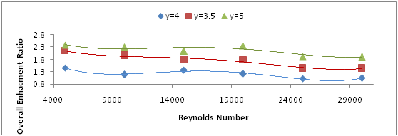
Overall Enhancement Ratio (plotted in fig 10) has been made and found that the performance ratio increases with increasing Reynolds number and decreasing twist ratio with the maximum for the twist ratio 2.38. The performance ratio of more than one indicates that the type of twist inserts can be used effectively for heat transfer augmentation
5. Conclusion
According to high performance results, the proposed method of heat transfer enhancement by Baffled reduced width twisted tape with holes (BRWTT) can be considered as a promising method of promoting heat transfer in the double pipe heat exchanger, For same twist ratio, Baffled reduced width twisted tape with holes shows higher heat transfer coefficient & friction factor increase, than other type because of higher degree of turbulence created For both tube and annulus side heat transfer enhancement, Nusselt number and friction factor are more dependent on Reynolds number at low values than high ones. Heat transfer, as well as friction factor increases with decreasing the Twist Ratio in the tube-side heat transfer enhancement by twisted tape at Re = 5000 , BRWTT giving a maximum heat transfer augmentation ratio of 3.299 compared to smooth tube with 3.0534 augmentation of friction factor. That is obtained by Twisted Tape BRWTT, y =5, with five hole, TT2 giving a maximum heat transfer augmentation ratio of 2.7353 compared to smooth tube with 2.29 augmentation of friction factor. That is obtained by Baffled reduced width Twisted Tape TT2, y =3.5, with five hole. TTI giving a maximum heat transfer augmentation ratio of 1.663 compared to smooth tube with 1.526 augmentation of friction factor. That is obtained by Twisted Tape TT1, y =4.
IJSER © 2014 http://www.ijser.org
International Journal of Scientific & Engineering Research, Volume 5, Issue 3, March-2014 - 1494 - ISSN 2229-5518
References
[1]. Manglik, R. M., “Heat Transfer Enhancement”, in “Heat Transfer Handbook”, Chap. 14, A. Bejan, and A. D. Kraus (editors), John Wiley & Sons Inc., New Jersey, (2003).
[2]. Ecke, R., “The Turbulence Problem, An Experimentalist’s Perspective”, Los Alamos Science, Number 29 2005, pp. 124-125. [3]. McComb, W. D, “The Physics of Fluid Turbulence”, Clarendon Press, Oxford, (1992), pp. 4-5.
[4]. Thianpong, C., Eiamsa-ard P., Wongcharee, K., “Compound heat transfer enhancement of a dimpled tube with a twisted tape swirl generator”, International Communications in Heat and Mass Transfer 36 (2009) pp. 698–704.
[5]. B. Silapakijwongkul, S. Eiamsa-ard and P. Promvonge, Effect of clockwise and counterclockwise twisted-tape turbulators on heat transfer
augmentation inside a double pipe heat exchanger. International Energy Journal.
[6]. Development of Heat Transfer Enhancement Techniques for External Cooling of an Advanced Reactor Vessel (2005)
[7]. Petukhov, B. S., “Heat Transfer and Friction in Turbulent Pipe Flow with Variable Physical Properties”, in “Advances in Heat Transfer”,
Vol.6, J. B. Hartnett, and T. F. Irvine, (editors) Academic Press Inc., (1970), pp. 503-564. [8]. Streeter, V. L., “Fluid Mechanics”, 9th edition McGraw-Hill Inc., New York, (1998).
[9]. Munson, B. R., and Young, D. F., “Fundamentals of Fluid Mechanics”, 4th Edition, John Wiley & Sons, Inc., (2002).
[10]. Colburn, A. P., Transactions of the AICHE 26 (1933). pp 174 cited in “Heat Transfer, a Practical Approach”, McGraw-Hill, New York,
(2002).
[11]. Dittus, F. W., and Boelter, L. M., University of California Publications on Engineering 2 (1930), p. 433, cited in “Heat Transfer, a Practical
Approach”, McGraw-Hill, New York, (2002).
[12]. Sieder, E. N., and Tate, G. E., “Heat Transfer and Pressure Drop of Liquids in Tubes”, Ind. Eng. Chem., vol. 8, pp. 1429-1435, 1936, cited in “Heat Exchanger Design Handbook”, D. B. Spalding (editor), Hemisphere Publishing Corporation, New York, (1983).
[13]. Çengel, Y. A., “Heat Transfer, a Practical Approach”, McGraw-Hill, New York, (2002).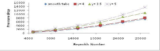
IJSER © 2014 http://www.ijser.org
International Journal of Scientific & Engineering Research, Volume 5, Issue 3, March-2014 - 1495 - ISSN 2229-5518
IJSER © 2014 http://www.ijser.org
International Journal of Scientific & Engineering Research, Volume 5, Issue 3, March-2014 - 1496 - ISSN 2229-5518
• Ossama thamer is currently pursuing master's degree program in mechanical engineering in Alnahreen University, Baghdad-Iraq, PH-07714565622. E-mail:
• Qasim Al-Saiman is currently PhD in chemical engineering at Alnahreen University, Baghdad-Iraq, PH-07704201337. E-mail: ds6mj8q@yahoo.com
IJSER © 2014 http://www.ijser.org