lowing diagram depicts the structure of the PIMS agent:
International Journal of Scientific & Engineering Research Volume 2, Issue 6, June-2011 1
ISSN 2229-5518
Power Infrastructure Monitoring System on
Embedded Web
Mr Ajay K. Kakde, Mr Ajay P. Thakare
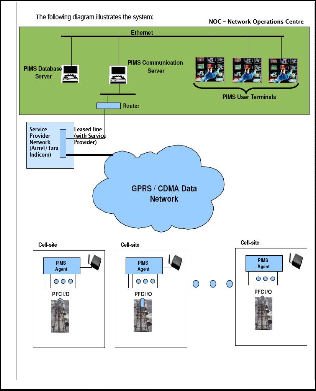
Abstract— PIMS NOC system is located centrally at the tower infrastructure service provider premises to monitor the various RMSs. The PIMS NOC is designed for modularity and scalability and comprises of a Communication Server, a Data Server and various User Terminals. Each Communication Server is connected to the GPRS/CDMA network service provider via a leased line. The bandwidth requirements of the leased line would be based on the total number of PIMS agents being monitored. PMS are received and processed by the Communication Server. The processed data is then passed onto the Data Server which primarily manages the tasks of storage and management of the PMS data. Various filtering options are provided to 'slice the data’ as per required views. The filtered data serves as input for report generation. Various types of reports can be generated based on user requirements.
Index Terms— PIMS, PIMS Agent, NOC, Data Server, Embedded Web, GPRS, socket server.
—————————— • ——————————
Each cell-site tower is equipped with a Power Manage- ment System (PMS) which is a critical component of the cell-site tower infrastructure. It's primary function is to ensure uninterrupted power supply to the various equipments present at the cell-site tower. Due to the criticality associated with the proper operation of the PMS, it is required that any malfunction in its op- eration is immediately reported to a centralized NOC as well as service personnel to initiate remedial measures. The PIMS NOC system is located centrally at the tower infrastructure service provider premises to monitor the various PMSs. The PIMS NOC is designed for modularity and scalability and comprises of a Communi- cation Server, a Data Server and various User Termin- als. Each Communication Server is connected to the GPRS/CDMA network service provider via a leased line. The bandwidth requirements of the leased line would be based on the total number of PIMS agents being monitored / controlled.
Asynchronous events / alarms that occur at the PMS are
received and processed by The Communication Server. The processed data is then passed onto the Data Server for storing in the database. In the case of alarms, ap- propriate visual alarms (based on criticality) are dis- played on User terminals and pre-configured actions (like sending SMS to pre-configured numbers) are initiated.
Periodic poll of the PIMS agents are carried out to obtain current health and status information.
2. LITERATURE REVIEW
At present and previously it was done by sending a person at the site either for preventive maintenance or for a service calls. Then the second visit for actual repairs and manual or computerized record which is prone to human errors. This is costly way of doing it also affects customer satisfaction. After the developments in the field of com- munication it has easier to handle this.
Embedded system hardware and software depends on the product type, analysis required and the communica- tion port available with the product or not. The user has to specify what is normal and what is abnormal. The timely report even if the product is functioning normal. Service call alerts etc. At the centre a server with suitable software to handle internet and a huge database is used and a provision for sending EMAILS on a given address as per the product is sent for immediate action so that no operator is required at the server centre. (Similar to ATM operations) GSM and GPRS are developed for cellular mobile communication.General block diagram for remote monitoring on embedded web shown below-
————————————————
Mr Ajay P. Thakare is currently pursuing Phd program in Nagpur Uni-
versity, India, (IEEE Member (USA) -41492816) IETE Fellow (F-122123) E-mail Id - apthakare40@gmail.com
IJSER © 2011 http://www.ijser.org
International Journal of Scientific & Engineering Research Volume 2, Issue 6, June-2011 2
ISSN 2229-5518
lowing diagram depicts the structure of the PIMS agent:
3.1 Figures
.
FIGURE: - 1. BLOCK DIAGRAM OF “REMOTE MONITORING SYSTEM “
The embedded system hardware and software depends on the product type, analysis required and the communi- cation port available with the product or not. The user has to specify what is normal and what is abnormal. The timely report even if the product is functioning normal. Service call alerts etc. At the centre a server with suita- ble software to handle internet and a huge database is used and a provision for sending EMAILS on a given ad- dress as per the product is sent for immediate action so that no operator is required at the server centre.
A robust communication framework for communication between the PIMS and its agents is put in place. The framework is based on GPRS or CDMA data connectivity between the PIMS communication server and the PIMS agents with the entire communication being TCP/IP based. An application based protocol framework is present for message exchange between the PIMS commu- nication server and the PIMS agents. Messages are de- fined for event reporting, health & status information, and control operations.
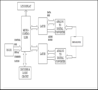
The PIMS agents are devices that co-habit with the PMS system at each cell tower location. They are connected to the PMS system for status / health monitoring. The fol-
FIGURE: - 2. BLOCK DIAGRAM OF PIMS AGENT
The PIMS agents are devices that co-habit with the PMS system at each cell tower location. They are con- nected to the PMS system for status / health monitoring. The following diagram depicts the structure of the PIMS agent. We monitor a given product by using the best (reli- able) and cheap mode of communication from the site to the central monitoring point in case occurrence of any ab- normalities in the product or after a period specified by the user of the system. Every site is added with a client unit which collects data from the product and identifies the abnormalities and communicates with the centre via GPRS
2.link on GSM/GPRS MODEM ,the centre is having a in- ternet connection with static IP and number of such clients can communicate with the centre as large as 2000
4. IMPLEMENTATION
Analog inputs from the sensors are given to the
ADC.
The digital inputs and the ADC output is given to
the microcontroller.
In the microcontroller these inputs are processed
using logic and digital circuits.
The processed output is given to the computer us-
ing RS232 and HyperTerminal functionality is used
IJSER © 2011 http://www.ijser.org
International Journal of Scientific & Engineering Research Volume 2, Issue 6, June-2011 3
ISSN 2229-5518
to observe the output.
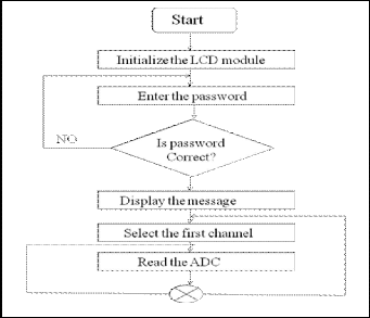
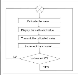
PIMS has 22 analog inputs and 16 digital inputs to which various sensors are used.Once the system is initialized PIMS reads data from all inputs. All the 22 analog and 16 digital channels are scanned and the data is sent to the processor. The Processor sends this data to monitoring
system. It reads the data from input and sends it to moni- toring system continuously
The embedded remote monitoring system completes the data Collection in the embedded platform and pro- vides the data to remote host through the TCP/IP proto- col from Web server. It creates condition to realize unat- tended management through providing Web-based graphical management interface for the Internet or LAN users
It eliminated the special client management software and realized unified management of various equipments in the network. Through existing public communications networks, without geographical restrictions, using a stan- dard Web browser, Users can directly access to the Web server in embedded devices and performance remote monitoring, diagnosis and maintenance of all nodes on the network Embedded system is a kind of special com- puter system which has limited resources and functions. To implement Web server in embedded system is charac- teristic of itself. Considering the need of large dynamic data exchange during equipment monitoring and control- ling is implemented through VB and ASP environment
1. System based on distributed architecture (for scalabil- ity)
2. Instantaneous notification of fault / alarm conditions to the PIMS central server.
3. Communication framework based on GPRS/CDMA data network – with the under- lying communication being TCP/IP based connec- tivity.
4. Modular scalability – The PIMS is designed to ensure that that the system is scalable in a modular fashion.
5. Logging the occurrence and clearing of all fault /
alarm conditions.
6. Visual overview of the status and health of all PMS at the PIMS central system.
7. Remote Control functions – the system can be ex- tended to carry out control functions from the NOC on a selected PMS
The microcontroller sent processed data to computer using RS 232 and data is monitored on HyperTerminal window. Here date, time and analog and digital output is displayed.
IJSER © 2011 http://www.ijser.org
International Journal of Scientific & Engineering Research Volume 2, Issue 6, June-2011 4
ISSN 2229-5518
� Compiler for 'C' programming.
� MS Hyperterminal.
� Internet data logger
� Socket Server etc.
� Monitoring system is developed to supply prac-
tical needs, is suitable for supporting mainten-
ance and other services and for prevention of
failures. It provides early warning of the prob-
lems.
� It reduces the manual work done in the cell sites.
Hence making monitoring easy.
� PIMS does not require complicated solutions and
high investment. Hence its maintenance is cheap.
� Ability to Monitor and Control remotely
� Efficient use of available Internet Network
� Real time monitoring and controlling
� Cost effective
1. Home protection systems
2. Manufacturing
3. Health Care
4. Military
5. Bio-Technology
1. Can be expanded into GSM, Satellite and Wi-Fi networks
2. Wireless sensors can be used
3. Implementation using Wi-Fi Ethernet within Or-
ganisation
4. Enabling text messages with desired parameters
� PC, Microchip programmer, debugger, CRO,
Multimeter.
� Microchip – PIC18F4520
� High Performance, Enhanced FLASH Microcon-
trollers with 10-Bit A/D
� On-Chip Program Memory: FLASH (bytes):-
32K
� # Single Word Instructions:- 16384
� On-Chip RAM (bytes):- 1536
� Data EEPROM:- 256
� Multiplexer – CD4051 BM 8:1 MUX for analog
inputs.
� Serial communication: - RS 232.
1. Yong-tao ZHOU, Xiao-hu CHEN, Xu-ping WANG, Chun-jiang YAO, 2008”: Design of Equipment Re- mote Monitoring System Based on Embedded Web”, IEEE, pp 73-78
2. Ali Ziya Alkar, 2009” An Internet Based Interactive Embedded Data- Acquisition System for Real-Time Applications”, IEEE, Vol .58.No.3, pp.522- 529.
3. D. Comer, Internetworking with TCP/IP Volume
I(Prentice-Hall, 1995)
4. Seifedine Kadry, Khaled Smaili, 2008” Control Sys-
tem for Internet Bandwidth Based on Java Technol-
ogy,” Journal of Theoretical and Applied information
Technology.
5. Mo Guan,Wei,Ying Bao, 2008 ” A Monitoring System
Based on Embedded Internet Technology for Embed-
ded Devices”, IEEE ,Vol.pp.5-8
IJSER © 2011 http://www.ijser.org