International Journal of Scientific & Engineering Research, Volume 2, Issue 12, December-2011 1
ISSN 2229-5518
Power-Quality improvement by multi pulse AC–
DC converters for Varying Loads
Ch.Punya Sekhar, C.Hari Krishna
Abstract— The present work is an endeavor towards analyzing the different multi-pulse converters in solving the harmonic problem in a three-phase converter system. The effect of increasing the number of pulses on the performance of AC to DC converters is analyzed.This paper presents the design and analysis of a novel 30-pulse ac–dc converter for harmonic mitigation under varying loads. The proposed multi pulse( 30-pulse) ac-dc converter is based on a polygon-connected autotransformer with reduced magnetics.The proposed ac–dc converter is able to eliminate lower than29th order harmonics in the ac supply current. Auto transformer is modified The resulting supply current is near sinusoidal in shape with low total harmonic distortion and a nearly unity power factor. Moreover, the design of an to make it suitable for retrofit applications, where presently a 6-pulse diode bridge rectifier is used. To validate the proposed approach, various power-quality indices are presented under varying loads. The proposed ac–dc converter is found to be suitable for retrofit applications with a large load variation and where harmonic reduction is more stringent. The laboratory prototype of the proposed autotransformer-based 30-pulse ac–dc converter is developed and test results are presented which validate the developed design procedure and the simulation models of this ac–dc converter.
Index Terms— Autotransformer, multipulse ac–dc converter, polygon connection, power-quality (PQ) improvement.
—————————— ——————————
I. INTRODUCTION
WITH the availability of low-cost and high-rating equipments has gained momentum recently [1]–[4]. These power processors find applications in various industries, such as electrochemical, petrochemical, large rating power supplies,adjustable speed ac motor drives, mining, steel, transportation,aerospace, etc. [5]. These applications using switching devices-based power processors help to achieve energy-efficient operation. But the nonlinear nature of these switching devices,such as diodes used in these power processors, causes harmonic current injection into the ac mains, thereby polluting the powerquality (PQ) at the point of common coupling (PCC). This, in turn, affects the nearby consumers, causing maloperation of sensitive electronic equipment. The drawbacks of harmonics have already gained much attention in literature [6]–[8]. More- over, an IEEE Standard 519 [9] has been established to impose strict restrictions on both utility and consumers. This has techniques. A diode-rectifier-based ac interface with additional switching devices or with passive filters has been proposed to improve the PQ indices [10], [11].
The PQ improvements in 3-phase ac–dc converters (ADCs) may be achieved using multipulse converters [12]– [20]. The multipulse converters are simple, robust, rugged, and more efficient. For applications where isolation is not required, autotransformer-based configurations are found to be more economical due to reduced magnetics, as the magnetics transfer only a small portion of the load power. Different configurations of 12-pulse and 18-pulse-based ADCs have been reported in the literature [12]–[18]. An 18- pulse ac–dc converter has been reported for power-supply applications [5], which results in a total harmonic distortion (THD) of supply current of 8.6%, which is not within IEEE Standard limits [9]. Miyari et al. [19] have used the concept
of dc-ripple reinjection for harmonic elimination, but the
THD of ac mains current is poor under light-load conditions.This Chen and Horng [20] have reported one configuration, which results in 28 steps of input current waveform. This configuration results in a THD of supply current as 6.54%, which deteriorates
at the reduced load.
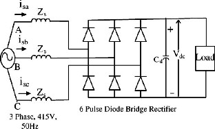
Fig. 1. Six-pulse diode-bridge rectifier fed load (topology
“A”).
In this work, a novel autotransformer-based 30-pulse ac– dc converter has been proposed for effective harmonic reduction.The reduced rating autotransformer is used to produce five sets of three-phase voltages, being fed to the diode-bridge rectifiers. The proposed ac–dc converter leads to savings in space, weight, size, and the overall cost of the power processing unit [21]. This ac–dc converter results in the elimination of up to the 29th harmonic in the supply current (the two lowest order harmonics are 29th and 31st, which have very small magnitude). Various experiments are conducted on the developed prototype of the proposed converter consisting of a reduced rating autotransformer and an
IJSER © 2011
http://www.ijser.org
International Journal of Scientific & Engineering Research, Volume 2, Issue 12, December-2011 2
ISSN 2229-5518

interphase transformer. The experimental results validate
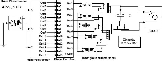
Fig. 2. Proposed 30-pulse ac–dc converter-fed varying load(topology B).
the simulation results for the proposed 30-pulse ac–dc
converter.
A set of tabulated results giving the comparison of different PQ indices, such as THD and crest factor (CF) of ac mains current, power factor (PF), displacement factor (DPF), distortion factor (DF), THD of supply voltage at PCC, and ripple factor (RF) at the dc bus is presented for
a load fed from an existing 6-pulse ac–dc converter, shown in Fig. 1 and referred to as topology “A” and a proposed 30-pulse ac–dc converter.
II. DESIGN OF THE PROPOSED 30-PULSE AC–DC CONVERTER
The proposed multipulse (30-pulse) ac–dc converter feeding varying loads is shown in Fig. 2. The complete circuit consists of an autotransformer, three-phase diode rectifiers, and a varying load.
A. Design of Autotransformer for the Proposed 30-Pulse AC–
DC Converter
The minimum phase shift required for proper harmonic elimination is given by [12]
Phase shift = 60 / Number of six-pulse converters (1)
To achieve the 30-pulse rectification, five sets of balanced three phase line voltages are to be produced, which are 12 out of phase with respect to each other. Fig. 2 shows the schematic diagram of a 30-pulse ac–dc converter with a phase shift of 12, referred as topology “B.” The basic arrangement of the auto transformer is shown in Fig. 3.
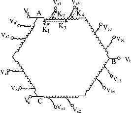
Fig. 3. Proposed autotransformer winding connection diagram
IJSER © 2011
http://www.ijser.org
International Journal of Scientific & Engineering Research, Volume 2, Issue 12, December-2011 3
ISSN 2229-5518
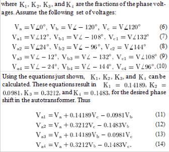
Three-phase ac voltages are given to the autotransformer, which produces five sets of balanced three-phase voltages of the same magnitude and distributed in time through a phase shift of 12 , as shown in Fig. 4. The number of turns of different windings in the autotransformer is calculated to result in 15-phase operation. Consider phase “a” voltages in Fig. 3 as
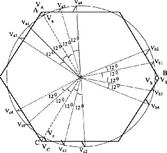
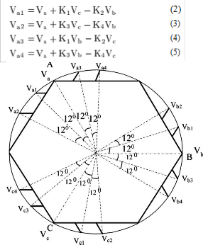
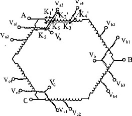
Fig. 4. Phasor diagram of different phase voltages in the proposed autotransformer-based 30-pulse ac–dc converter.
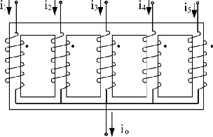
Fig. 6. Phasor diagram of different phase voltages in the proposed autotransformer-based 30-pulse ac–dc converter.
Fig. 5. Proposed autotransformer winding connection
diagram for retrofit applications
IJSER © 2011
http://www.ijser.org
International Journal of Scientific & Engineering Research, Volume 2, Issue 12, December-2011 4
ISSN 2229-5518
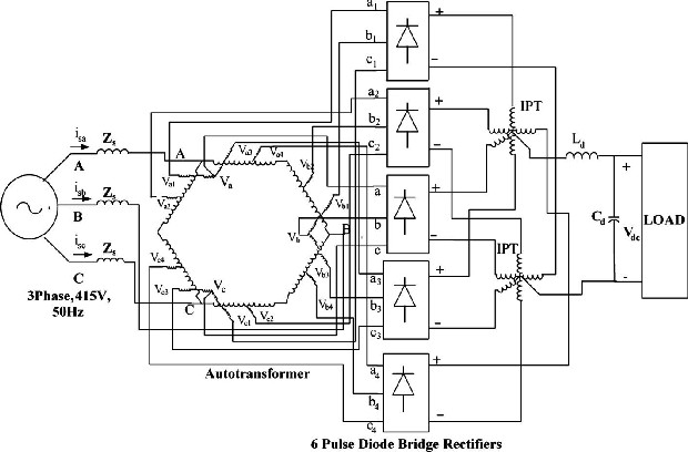
Fig. 7. Winding configuration of an interphase transformer.
Fig. 8. Proposed 30-pulse ac–dc converter-fed varying load (topology C) for retrofit applications.
A phase-shifted voltage is obtained by tapping a portion
(0.14189) of phase voltage and connecting one end of an approximately 0.0981 times of phase voltage to this tap. Thus, the autotransformer can be designed with these known values of winding constants . Due to 30-pulse rectification, the average dc-link voltage in the converter described before, referred to as topology “B,”is higher by about 5% than that of a 6-pulse diode-bridge rectifier output. The design of an autotransformer is modified to make it suitable for retrofit applications. The number of turns in different portions of windings are calculated as per the new winding constants designed and these constants are calculated. The output voltages of the autotransformer are tapped at 0.95 times the input voltage, while ensuring their relative phase-shift angle. This ensures that all of the autotransformer output voltages are still having the required phase shift of 12 with respect to each other (for achieving the 30-pulse operation). Fig. 5 shows the winding configuration of the autotransformer for retrofit applications. The Phasor diagram of different phase voltages for retrofit applications is shown in Fig. 6. The value of these new

winding constants is
Further, as one of the diode rectifier bridges is directly Connected to the line voltage, this voltage is also reduced by calculating the new winding constant as shown in

Fig. 5. This winding constant is calculated as

With these winding constants, the same dc-link voltage is ob tained as that of a 6-pulse diode-bridge rectifier, thus making it suitable for retrofit applications. The schematic diagram of the interphase transformer used is shown in Fig. 7. The proposed configuration of the 30-pulse ac–dc converter, shown in Fig. 8, is referred to as topology “C.”
The kilovolt-ampere rating of the autotransformer and interphase transformer is calculated as [12]
B. Intephase Transformer
The five sets of voltages produced by the autotransformer
are given for five diode rectifier bridges, which rectify these
IJSER © 2011
http://www.ijser.org
International Journal of Scientific & Engineering Research, Volume 2, Issue 12, December-2011 5
ISSN 2229-5518
voltages. These obtained dc voltages are also phase shifted through a 12 angle. These voltages are applied to the
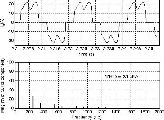
Fig. block 9. MATLAB diagram of the proposed 30-pulse ac–dc converter-fed load (topology “C”).
interphase transformer to ensure independent operation of the rectifier circuits.Fig. 7 shows the winding configuration of the proposed interphase transformer. This arrangement ensures 1200 conduction of each diode. It can be seen that the interphase transformer carries one-fifth of the load current, thus leading to the reduction in rating of the interphase transformer
III. SIMULATION
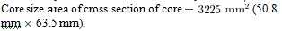
The complete system consisting of the proposed autotrans- Former based ac–dc converter fed load is simulated in the MATLAB environment along with Simulink and Power System Block set (PSB) toolboxes. The MATLAB model of the proposed ac–dc-converter-fed load is shown in Fig. 9. The detailed parameters of the proposed system are given in the Appendix. The source impedance has been kept at a practical value of 3% in all of the simulations. The load is varied on the proposed ac–dc converter to study its effect on various PQ indices. To realize the proposed converter configuration, three single phase autotransformers are designed and developed. The design details of the autotransformers are given below
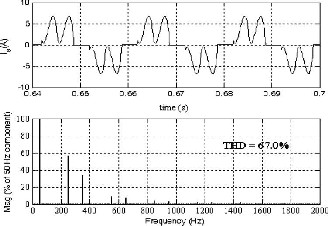
Fig. 10. Supply current waveform along with its harmonic spectrum at full load in topology “A.”


IJSER © 2011
http://www.ijser.org
International Journal of Scientific & Engineering Research, Volume 2, Issue 12, December-2011 6
ISSN 2229-5518
Fig. 11. Supply current waveform along with its harmonic
spectrum at light load in topology “A.”
IV. RESULTS AND DISCUSSION
To compare the performance of the proposed 30-pulse ac–dc converter with the existing 6-pulse ac–dc converter, first a 6-pulse diode-bridge rectifier-fed varying load (topology “A”) has been designed, modeled, and simulated. The complete system has been designed for a 3-phase, 415-V, 50-Hz, 10-kW load. The supply-current waveform along with its harmonic spectrum at full load is shown in Fig. 10, showing a THD of the ac mains current as 31.4%. The THD of the ac mains current deteriorates to 67.0% at light load (20%), as shown in Fig. 11. Moreover, the power factor at full load is 0.943, which deteriorates to 0.81, (as shown in Table I) as the load is reduced to 20%. These PQ indices are not within IEEE Standard 519 [9] limits. These results indicate the need to improve PQ in ADCs, which can replace the existing six-pulse ac–dc converter at minimal cost.
A. Performance of Proposed 30-Pulse AC–DC Converter-Fed
Load
To achieve various PQ indices within IEEE standard 519 limits, a novel 30-pulse ac–dc converter, referred to as topology“B” has been designed, modeled, and simulated in a MATLAB environment. The THD of the ac mains current at full load is 2.34% as shown in Fig. 12 and that under light load (20% of full load) is 3.46%, as shown in Fig. 13. These parameters are within IEEE Standard limits [9]. But the dc-link voltage is higher by about 5% compared to that of a 6-pulse diode bridge rectifier output due to the 30-pulse rectification. The autotransformer design is modified for retrofit applications as explained earlier. The observed performance of the proposed ac–dc converter is shown in Fig. 14, showing the waveforms of supply voltage , supply current , and dc-link voltage . The waveform of supply current at full load along with its harmonic spectrum is shown in Fig. 15, showing the THD as 2.63% at full load. It clearly shows the elimination of harmonics in the supply current, resulting in improvement in THD. Under light load conditions (20% of full load), the waveform of supply current along with its harmonic spectrum is shown in Fig. 16. It can be observed that all of the harmonic components are always less than
2% of the fundamental current, thus qualifying the IEEE
standard 519 [9].
To demonstrate the capability of the proposed 30- pulse ac–dc converter under load variation, the load is
varied and its effect on various PQ indices is shown in

Table II. It can also be observed from Table II that the proposed converter results in a nearly unity power factor in a wide load variation and the THD of the supply current is always less than 5%. This is within the IEEE Standard 519 limits [9]. The comparison of different PQ indices of a load fed from a 6-pulse ac–dc converter and the proposed ac–dc converter is shown in Table I. This table shows the quantitative improvement in these indices with the proposed ac–dc converter. The graphical variation of THD of the ac mains current and power factor with load is shown in Figs. 17 and 18, respectively, clearly showing the remarkable improvement in these PQ indices. It is also observed from Table I that the rms current drawn from the three-phase ac mains has decreased reasonably compared to that in a 6-pulse ac–dc converter-fed system under full load as well as light load conditions. More ver, there is an improvement in the dc-link voltage regulation. The ripple in dc-link voltage has decreased sharply, indicating the need for a lower rating capacitor filter for maintaining the same ripple factor, resulting in further savings in capital cost.
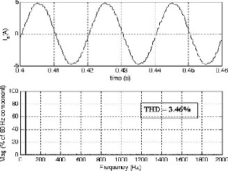
Fig. 12. Supply-current waveform along with its harmonic spectrum at full load in topology “B.”
IJSER © 2011
http://www.ijser.org
International Journal of Scientific & Engineering Research, Volume 2, Issue 12, December-2011 7
ISSN 2229-5518
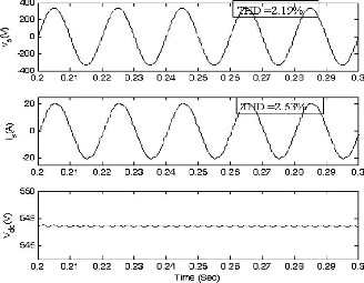
Fig. 13. Supply current waveform along with its harmonic
spectrum at light load in topology “B.”
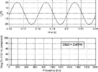
Fig.14. wave forms of supply voltage, supply current and
DC link voltage in topology “C”.
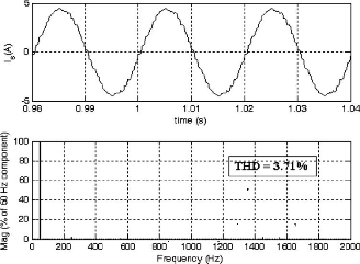
Fig. 15. AC mains current waveform along with its harmonic spectrum at full load for topology “C.”
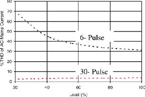
Fig. 16. AC mains current waveform along with its
harmonic spectrum at light load for Topology “C.”
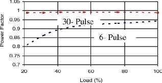
Fig. 17. Variation of THD of an ac mains current with a load in topology “A” and in topology “C.”
Fig. 18. Variation of power factor with load in topology
“A.” and in topology “C.”
V. CONCLUSION
The converters are studied in terms of harmonic spectrum of ac mains current, THD, distortion factor, displacement power factor and actual power factor in the AC mains. It is concluded therefore that in general with increase in number of pulses in multi-pulse case the performance parameters of these converters are remarkably improved.A new 30-pulse ac–dc converter- feeding varying load has been designed, modeled, simulated, and developed to demonstrate its improved performance. The proposed 30-pulse ac–dc converter consists of a reduced rating polygon connected autotransformer for producing the desired phase-shifted voltages and is suitable for retrofit applications, where presently a 6-pulse diode-bridge rectifier is used. It has resulted in the elimination of a lower than 29th harmonic in the supply current. The proposed ac–dc converter has resulted in a THD of supply current of less than 5% in a wide operating range of the load with nearly unity power factor operation. The proposed converter results
IJSER © 2011
http://www.ijser.org
International Journal of Scientific & Engineering Research, Volume 2, Issue 12, December-2011 8
ISSN 2229-5518
in the reduction in rating of the magnetics, leading to
savings in weight, size, volume, and, finally, the overall cost of the converter system. The results obtained on the developed converter configuration also validate the simulated models and the design procedure.
REFERENCES
*1+ B. K. Bose, “Recent advances in power electronics,”IEEE Trans.
Power Electron., vol. 7, no. 1, pp. 2–16, Jan. 1992.
[2] G. T. Heydt, Electric Power Quality.West LaFayette, IN: Stars in a
Circle Publication, 1991.
[3] M. H. J. Bollen, Understanding Power Quality Problems: Voltage Sags
and Interruptions. Piscataway, NJ: IEEE Press, 2000.
*4+ A. Ghosh and G. Ledwich, “Power quality enhancement using
Custom power devices,” in . Norwell, MA: Kluwer, 2002.
[5] F. J. M. de Seixas and I. Barbi, “A 12 kW three-phase low THD
rectifier with high frequency isolation and regulated dc output,”
IEEE Trans.Power Electron., vol. 19, no. 2, pp. 371–377, Mar. 2004.
*6+ R. Redl, P. Tenti, and J. D. Van Wyk, “Power electronics polluting
effects,” IEEE Spectr., vol. 34, no. 5, pp. 32–39, May 1997.
*7+ D. D. Shipp and W. S. Vilcheck, “Power quality and line
Considerations for variable speed ac drives,” IEEE Trans. Ind. Appl., vol.
32, no. 2, pp. 403–409, Mar./Apr. 1996.
*8+ D. A. Jarc and R. G. Schieman, “Power line considerations for vari-
able frequency drives,” IEEE Trans. Ind. Appl., vol. IA-21, no. 5,
pp. 1099–1105, Sep. 1985.
[9] IEEE Guide for Harmonic Control and Reactive Compensation of
Static Power Converters, IEEE Std. 519-1992.
[10] B. Singh, B. N. Singh, A. Chandra, K. Al-Haddad, A. Pandey, and
D.P. Kothari, “A review of three-phase improved power quality ac-dc
converters,” IEEE Trans. Ind. Electron., vol. 51, no. 3, pp. 641–660,
Jun. 2004.
*11+ M. Rastogi, R. Naik, and N. Mohan, “Optimization of a novel dc
linkcurrent modulated interface with 3-phase utility systems to minimize
line current harmonics,” in Proc. IEEE Power Eng. Soc. Conf., 1992,
pp. 162–167.
[12] D. A. Paice, Power Electronic Converter Harmonics: Multipulse
Methods for Clean Power. New York: IEEE Press, 1996.
[13] “Multipulse Converter System,” U.S. Patent 4 876 634, Oct. 24,
1989.
*14+ P. W. Hammond, “Autotransformer,” U.S. Patent 5 619 407, Apr.
8,1997.
*15+ D. A. Paice, “Simplified Wye Connected 3-Phase to 9-Phase
Autotransformer,” U.S. Patent No. 6 525 951 B1, Feb. 25, 2003.
*16+ J. Ferens, H. D. Hajdinjak, and S. Rhodes, “18-Pulse Rectification
System Using a Wye Connected Autotransformer,” U.S. Patent No.
6 650 557 B2, Nov. 18, 2003.
*17+ G. R. Kamath, B. Runyan, and R. Wood, “A compact
Autotransformer based 12-pulse rectifier circuit,” in Proc. IEEE IECON
Conf., 2001, pp1344–1349.
*18+ K. Oguchi and T. Yamada, “Novel 18-pulse diode rectifier circuit
with non-isolated phase shifting transformers,” Proc. Inst. Elect.
Eng. Electr. Power Appl., vol. 14, no. 1, pp. 1–5, Jan. 1997.
[19] S. Miyairi, S. Iida, K. Nakata, and S. Masukawa, “New method for
reducing harmonics involved in input and output of rectifier with inter-
phase transformer,” IEEE Trans. Ind. Appl., vol. 22, no. 5.

Ch.punya sekhar graduated in Electrical and Electronics Engineering from Chirala Engineering College, in 2008.He is currently a post graduate scholar in the EEE department of Mother Teresa Institute Of Science & Technology ,Sathupally, pursuing the masters degree in Power Electronics & Electrical Drives

Chalasani Hari Krishna was born in 1982. He graduated from Jawaharlal Nehre Technological University, Hyderabad in the year 2003. He received M.E degree from Satyabama University, Chennai in the year 2005. He presently Associate Professor in the Department of Electrical and Electronics Engineering at Mother Teresa
Institute of Science and Technology, India. His
research area includes DTC and Drives.
IJSER © 2011
http://www.ijser.org