International Journal of Scientific & Engineering Research, Volume 4, Issue 9, September-2013 9
ISSN 2229-5518
Power Quality Improvement of Grid Interfacing Inverter Using SRF Algorithm for Renewable Energy Sources
Dr.K.Ravichandrudu 1, Pattabi Nissy 2,Mr.P.Yohan Babu3,Mr.G.V.P.Anjaneyulu4,
1,2,3 Krishnaveni Engineering College For Women,Narasaraopet,Guntur,AP,India.
4Reaserch scholar SVU College of engineering,S.V.U.,Tirupathi.
Abstract—This paper presents a three-phase Active Power Conditioner to improve Power Quality of Grid Interfacing Inverter Using SRF Algorithm for Renewable Energy Sources. The grid interfacing inverter performs over all operation for the mitigation of harmonics. The synchronous reference method is used to detect the harmonics and generates the accurate value for grid interfacing inverter. The SRF based inverter constitutes the fast and dynamic response for the mitigation of harmonics and improves the power quality. The grid interfacing inverter manages the active and reactive power that harvested from the renewable energy sources.
The Simulations using MATLAB / SIMULINK are carried out to verify the performance of the proposed model . The results shows the control strategy improves the dynamic response, high accuracy of tracking the DC-voltage reference frame wind generator, and strong robustness to load parameters variation.
Keywords— Active power filter, SRF algorithm, Distributed generation, Grid interconnection, Hysteresis controller.
INTRODUCTION
The use of fossil fuels for electric power generation has imposed several problems on the environment including global warming and greenhouse effect. This has led to an era in which the increasing power demand will be met by Distributed Generation (DG) system which are based on renewable energy sources such as solar power, wind power, small hydro power etc. [1]-[2].
The DG systems are distributed near the user's facility. These systems are mainly small scale generations having capacity less than 20MW. These Distributed Generation (DG) systems need to be controlled properly in order to ensure sinusoidal current injection into the grid. However, they have a poor controllability due to their intermittent characteristics [3]. Grid connected inverter is the key element to maintain voltage at the point of common coupling (PCC) constant and to ensure power quality improvements. For safe and reliable operation of power system based on DG system, usually power plant operators should satisfy the grid code requirements such as grid stability, fault ride through, power quality improvement, grid synchronization and power control etc. The major issue associated with DG system is their synchronization with utility
voltage vector [4]. The information about the phase angle of utility voltage vector is accurately tracked in
order to control the flow of active and reactive power and to turn on and off power devices.
The DG systems are highly intermittent power generation system and their power output depends heavily on the natural conditions. To connect the DG systems with the utility grid various grid code requirements must be met. But as DG system are fragile power generation systems and their characteristics are highly intermittent, power electronics converter plays a very vital role. Whenever a DG system is required to be connected to the utility grid, two types of converter comes into picture. First is the Source-side converter which helps to ensure maximum power point tracking (MPPT) and the other is Grid-side converter which helps to maintain the grid connections standards. The proper operation of grid connected inverter system is determined by grid voltage conditions such as phase, amplitude and frequency. In such applications, an accurate and fast detection of the phase angle, amplitude and frequency of the grid voltage is essential. Various grid synchronization algorithms for phase tracking of the 3-phase system Renewable energy source (RES) integrated at distribution level is termed as distributed generation (DG). The utility is concerned due to the high penetration level of intermittent RES in distribution systems as it may pose a threat to network in terms of stability, voltage regulation and power-quality (PQ) issues. Therefore, the DG systems are required to comply with strict technical and regulatory frameworks to ensure safe, reliable and efficient operation of overall network. With the advancement in power electronics and digital control technology, the DG systems can now be actively controlled to enhance the system operation with improved PQ at PCC. However, the extensive use of power electronics based equipment and non-linear loads at PCC. generate harmonic currents, which may deteriorate the quality of power [3]-[5].
The widespread increase of non-linear loads nowadays, significant amounts of harmonic currents are being injected into power systems. Harmonic currents flow through the power system impedance, causing voltage distortion at the
IJSER © 2013 http://www.ijser.org
International Journal of Scientific & Engineering Research, Volume 4, Issue 9, September-2013 10
ISSN 2229-5518
additional hardware cost. However, in this paper authors have incorporated the features of APF in the, conventional inverter interfacing renewable with the grid, without any additional hardware cost. That conventional inverter is called as a "grid interfacing inverter". The inverter is controlled to perform as a
multifunction device by incorporating active power filter functionality. The inverter can thus be utilized as: 1) power converter to inject power generated from RES to the grid, and 2) shunt APF to compensate current unbalance, load current harmonics, load reactive power demand and load neutral current. All of these functions may be accomplished either individually or simultaneously.
figure 1
currents’ frequencies. The distorted voltage waveform causes harmonic currents to be drawn by other loads connected at the point of common coupling (PCC). The existence of current and voltage harmonics in power systems
increases losses in the lines, decreases the power factor and can cause timing errors in sensitive electronic equipments
addition to the hazard of cables and transformers overheating The harmonic currents and voltages produced by balanced 3- phase non-linear loads such as motor drivers, silicon controlled rectifiers (SCR), large uninterruptible power supplies (UPS) are positive-sequence harmonics (7th, 13th, etc.) and negative-sequence harmonics (5th, 11th, etc.). However, harmonic currents and voltages produced by single phase non-linear loads such as switch-mode power supplies in computer equipment which are connected phase to neutral in a
3-phase 4-wire system are third order zero-sequence harmonics (triplen harmonics—3rd, 9th, 15th, 21st, etc.). These triplen harmonic currents unlike positive and negative- sequence harmonic currents do not cancel but add up arithmetically at the neutral bus. This can result in neutral current that can reach magnitudes as high as 1.73 times the phase current. In the third harmonic can reduce energy efficiency. [6]
The traditional method of current harmonics reduction involves passive LC filters, which are its simplicity and low cost. However, passive filters have several drawbacks such as large size, tuning and risk of resonance problems. The increased severity of harmonic pollution in power networks has attracted the attention of power electronics and power system engineers to develop dynamic and adjustable solutions to the power quality problems. Such equipment, generally known as active filters (AF’s) [7], Active power filters (APF) are extensively used to compensate the load current harmonics and load unbalance at distribution level. This results in an
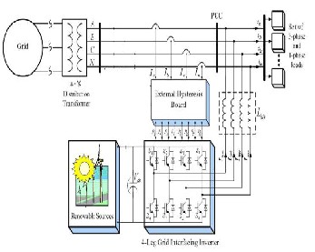
In this paper, it is shown that using an adequate control strategy, with a four-leg four-wire grid interfacing inverter, it is possible to mitigate disturbances like voltage unbalance. The topology of the investigated grid interfacing inverter and its interconnection with the grid is presented in Fig. 1. It consists of a four-leg four-wire voltage source inverter. The voltage source inverter is a key element of a DG system as it interfaces the renewable energy source to the grid and delivers the generated power. In this type of applications, the inverter operates as a current controlled voltage source. Fourth leg is used for neutral connection. The RES may be a DC source or an AC source with rectifier coupled to dc-link. In this paper wind energy is used as a RES, the variable speed wind turbines generate power at variable ac voltage. Thus, the power generated from these renewable sources needs to convert in dc before connecting on dc-link [8]–[10]. The simulink model of wind farm is given in Fig2.Wind farm generates a variable ac supply; this variable ac supply is converted into dc by connecting a rectifier at output side.
The paper is arranged as follows: Section II describes the system under consideration and the controller for grid interfacing inverter. simulation study is presented in Section III. Section IV concludes the paper.
2.SYSTEM DESCRIPTION
A. DC-Link Voltage and Power Control Operation
Due to the intermittent nature of RES, the generated power is
of variable nature. The dc-link plays an important role in transferring this variable power from renewable energy source to the grid. RES are represented as current sources connected to the dc-link of a grid-interfacing inverter. Fig. 2 shows the systematic representation of power transfer from the renewable energy resources to the grid via the dc-link. The current injected by renewable into dc-link at voltage level Vdc can be given as
𝑰𝒅𝒄𝟏=𝑷𝑹𝑬𝑺𝑽𝒅𝒄 (1)
IJSER © 2013 http://www.ijser.org
International Journal of Scientific & Engineering Research, Volume 4, Issue 9, September-2013 11
ISSN 2229-5518
figure 2
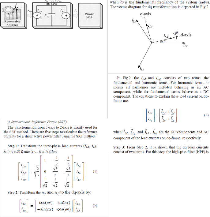
. DC-Link equivalent diagram. where PRES is the power generated from RES.The current flow on the other side of dc- link can be represented as
𝑰𝒅𝒄𝟐=𝑷𝒊𝒏𝒗𝑽𝒅𝒄=𝑷𝑮+𝑷𝑳𝒐𝒔𝒔𝑽𝒅𝒄 (2)
Where 𝑃𝑖𝑛𝑣,𝑃𝐺 𝑎𝑛𝑑 𝑃𝑙𝑜𝑠𝑠 are total power available at grid-
interfacing inverter side, active power supplied to the grid and
inverter losses, respectively. If inverter losses are negligible
then 𝑷𝑹𝑬=PG
B. Control of Grid Interfacing Inverter
control diagram of grid- interfacing inverter for a 3-phase
4-wire system is shown in Fig. 3. The fourth leg of inverter is used to compensate the neutral current of load. The main aim of proposed approach is to regulate the power at PCC during
1) PRES=0 , 2) PRES< Total load power (PL) and 3) PRES>PL.
IJSER © 2013 http://www.ijser.org
International Journal of Scientific & Engineering Research, Volume 4, Issue 9, September-2013 12
ISSN 2229-5518
The control diagram of grid- interfacing inverter for a 3-phase
4-wire system is shown in Fig. 3. The fourth leg of inverter is used to compensate the neutral current of load. The main aim of proposed approach is to regulate the power at PCC during:
1) PRES=0 , 2) PRES< Total load power (PL) and 3) PRES>PL
While performing the power management operation, the inverter is actively controlled in such a way that italways draws/ supplies fundamental active power from/ to the grid. If the load connected to the PCC is non-linear or unbalanced or the combination of both, the given control approach also
III. SIMULATION RESULTS
In order to verify the proposed control approach to achieve
multi-objectives for grid interfaced DG systems connected to a 3-phase 4-wire network, an extensive simulation study is carried out using MATLAB/Simulink. A 4-leg current controlled voltage source inverter is actively controlled to achieve balanced sinusoidal grid currents at unity power factor
(UPF) despite of highly unbalanced nonlinear load at PCC under varying renewable generating conditions. A RES with variable output power is connected on the dc-link of grid- interfacing inverter. The SRF algorithm accurately calculated the values of error and the grid interfacing inverter injects immediately after the 0.72s, the SRF algorithm improves the dynamic response when compared to the normal PLL. An unbalanced 3-phase 4-wire nonlinear load, whose unbalance, harmonics, and reactive power need to be compensated, is
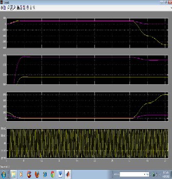
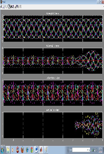
connected on PCC. The waveforms of grid voltage(𝑉𝑎,𝑉𝑏,𝑉𝑐) , grid currents (𝐼𝑎,𝐼𝑏,𝐼𝑐𝑎𝑛𝑑 𝐼𝑛 ), unbalanced load current and inverter currents 𝐼𝑙𝑎,𝐼𝑙𝑏,𝐼𝑙𝑐𝑎𝑛𝑑 𝐼𝑙𝑛 are shown in Fig. 4. The corresponding active-reactive powers of grid (𝑃𝑙𝑜𝑎𝑑,𝑄𝑙𝑜𝑎𝑑), load and inverter(𝑃𝑖𝑛𝑣 𝑄𝑖𝑛𝑣) are shown in Fig. 5.
Positive values of grid active-reactive powers and inverter
active-reactive powers imply that these powers flow from grid side towards PCC and from inverter towards PCC, respectively. The active and reactive powers absorbed by the load are denoted by positive signs. Initially, the grid- interfacing inverter is not connected to the network (i.e., the load power demand is totally supplied by the grid alone). Therefore, before time t=0.72 s, the grid current profile in Fig.
4(b) is identical to the load current profile of Fig. 4(c). At s, the grid-interfacing inverter is connected to the network. At t=0.72 s, this instant the inverter starts injecting the current in such a way that the profile of grid current starts changing from unbalanced non linear to balanced sinusoidal current as shown in Fig. 4(b). As the inverter also supplies load neutral current
demand, the grid neutral current (𝐼𝑛) becomes zero after s
t=0.72 s At t=0.72 s, the inverter starts injecting active power
generated from RES 𝑃𝑅𝐸𝑆⋍𝑃𝑖𝑛𝑣 . Since the generated power is
more than the load power demand the additional power is fed
back to the grid. The negative sign of 𝑃𝑔𝑟𝑖𝑑 , after time 0.72 s
suggests that the grid is now receiving power from RES.
Moreover, the grid-interfacing inverter also supplies the load reactive power demand locally. Thus, once the inverter is in operation the grid only supplies/receives fundamental active power. At t=0.82 s, the active power from RES is increased to evaluate the performance of system under variable power generation from RES. This results in increased magnitude of inverter current. As the load power demand is considered as constant ,this additional power generated from RES flows towards grid, which can be noticed from the increased magnitude of grid current as indicated by its profile. At t=0.92s;
the power available from RES is reduced. The corresponding change in the inverter and grid currents can be seen from Fig. 4. The active and reactive power flows between the inverter, load and grid during increase and decrease of energy generation from RES can be noticed from Fig. 5. The dc-link voltage across the grid- interfacing inverter (Fig. 5(d)) during different operating condition is maintained at constant level in order to facilitate the active and reactive power flow. Thus from the simulation results, it is evident that the grid-interfacing inverter can be effectively used to compensate the load reactive power, current unbalance and
IJSER © 2013 http://www.ijser.org
International Journal of Scientific & Engineering Research, Volume 4, Issue 9, September-2013 13
ISSN 2229-5518
current harmonics in addition to active power injection from
RES.
Figure 5
figure 3
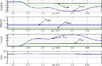
Figure 4
V. CONCLUSION
This paper has presented a novel control of an existing gridinterfacing inverter to improve the quality of power at PCC for a 3-phase 4-wireDGsystem. It has been shown that the grid-interfacing inverter can be effectivel y utilized for power conditioning without affecting its normal operation of real power transfer with integration of wind energy system and PV model. The grid-interfacing inverter with the proposed approach can be utilized to:
i) inject real power generated from RES to the grid, and/or, ii) operate as a shunt Active Power Filter (APF).
This approach thus eliminates the need for additional power conditioning equipment to improve the quality of power at PCC. Extensive MATLAB/Simulink simulation as well as the DSP based experimental results have validated the proposed approach and have shown that the grid-interfacing inverter can be utilized as a multi-function device. It is further demonstrated that the PQ enhancement can be achieved under three different scenarios:
1) 𝑃𝑅𝐸𝑆 = 0,
2)𝑃𝑅𝐸𝑆 < 𝑃𝐿𝑜𝑎𝑑 ,and
3)𝑃𝑅𝐸𝑆 > 𝑃𝐿𝑜𝑎𝑑
The current unbalance, current harmonics and load reactive
power, due to unbalanced and non-linear load connected to the PCC, are compensated effectivel y such that the grid side currents are always maintained as balanced and sinusoidal at unity power factor. Moreover, the load neutral current is prevented from flowing into the grid side by compensating it
IJSER © 2013 http://www.ijser.org
International Journal of Scientific & Engineering Research, Volume 4, Issue 9, September-2013 14
ISSN 2229-5518
locally from the fourth leg of inverter. When the power generated from RES is more than the total load power demand, the grid-interfacing inverter with the proposed control approach not only ful fills the total load active and reactive power demand (with harmonic compensation) but also delivers the excess generated sinusoidal active power to the grid at unity power factor.
Figire 4 and figure 5 shows the results that the SRF based Grid interfacing inverter improves the dynamic perfprmance of the renewable energy sources.
REFERENCES
[1] Energy Information Administration, "Greenhouse Gases, Climate Change, and Energy", http://www.eia.doe.gov/bookshelf/brochures/greenhouse/Chapter1.ht m Accessed: 19 March 2009.
[2] National Renewable Energy Laboratory, ―Learning About
Renewable Energy‖ http://www.nrel.gov/learning/ Accessed: 19
January 2009.
[3] J. M. Guerrero, L. G. de Vicuna, J. Matas, M. Castilla, and J. Miret, “A wireless controller to enhance dynamic performance of parallel in-verters in distributed generation systems,” IEEE Trans. Power Elec-tron., vol. 19, no. 5, pp. 1205–1213, Sep. 2004.
[4] J. H. R. Enslin and P. J. M. Heskes, “Harmonic interaction between a large number of distributed power inverters and the distribution net-work,” IEEE Trans. Power Electron., vol. 19, no. 6, pp. 1586–1593, Nov. 2004.
[5] Telmo Santos,J.G.Pinto, P.Neeves,D.Goncalves, Joao L. Afonso," comparision of three control theoriesfor single phase active filters,"IEEE Ind.Elcetron.society.,Nov.2009.
. [6J. P. Pinto, R. Pregitzer, L. F. C. Monteiro, and J. L. Afonso, “3-
phase 4-wire shunt active power filter with renewable energy interface,” presented at the Conf. IEEE Rnewable Energy & Power Quality, Seville,Spain, 2007
[6] F. Blaabjerg, R. Teodorescu, M. Liserre, and A. V. Timbus, “Overview of control and grid synchronization for distributed power generation systems,” IEEE Trans. Ind. Electron., vol. 53, no. 5, pp.
1398–1409, Oct. 2006.
.[7] M.J. Newman, D.N.Zmood, D.G.Holmes, “Stationary frame harmonic reference generation for active filter systems”, IEEE Trans.
on Ind. App., Vol. 38, No. 6, pp. 1591 – 1599, 2002.
IJSER © 2013 http://www.ijser.org