International Journal of Scientific & Engineering Research Volume 4, Issue 1, January-2013 1
ISSN 2229-5518
Pilot Channel Estimation: A Performance Analysis of
OFDM
Keshav Kumar, Amit Grover
Abstract
We prefer OFDM technique to achieve high data rates in mobile environment. The task of estimating the frequency response of the radio channel which the transmitted signal travels before reaching the receiver antenna is known as Channel Estimation. A dynamic estimation of channel is necessary before the demodulation of OFDM signals since the radio channel is frequency selective and time-variant for wideband mobile communication systems. In this article the channel estimation techniques for OFDM systems based on pilot arrangements are investigated. The channel estimation based on comb type pilot arrangement is studied through different algorithms for both estimating channel at pilot frequencies and interpolating the channel. The estimation of channel at pilot frequencies is based on LS and LMS while the channel interpolation is linear interpolation, second order interpolation, low-pass interpolation, spline cubic interpolation, and time domain interpolation. Time-domain interpolation [18] is obtained by passing to time domain through IDFT, zero padding and going back to frequency domain through DFT. In addition, the channel estimation based on block type pilot arrangement is performed by sending pilots at every sub-channel and using this estimation for a specific number of symbols like BPSK, QPSK and 16 QAM has been carried out. The Performance comparison of all schemes by measuring bit error rate using different modulation techniques like 16QAM, QPSK, and BPSK has been discussed. Simulation results shows that comb-type pilot based channel estimation with DFT interpolation [16] performs the best among all other comb based channel estimation algorithms. This is again expected since the comb type channel estimation allows the tracking of fast fading channels and low pass interpolation does the interpolation in such a way that mean square error is minimized. For fast varying channels, performance of comb arrangement with low pass interpolation is much better than other. It has been concluded that block type of arrangement performs better when the channel is changing slowly and the comb type channel estimation allows the tracking of fast fading channels.
Keywords: Orthogonal-frequency-division-multiplexing (OFDM), Quadrature Amplitude Modulation (QAM), Quadrature Phase Shift Key (QPSK), Binary Phase Shift Key (BPSK), Inter-symbol Interference (ISI), Inter Channel Interference (ICI), Linear Minimum mean-squared error (LMMSE), Least Square Error (LSE).
------------------------ ------------------------
1. Introduction to OFDM
Orthogonal frequency division multiplexing (OFDM) is based on multicarrier communication techniques which are based on the concept of dividing the total signal bandwidth into number of subcarriers and the information is transmitted on each of the subcarriers. In OFDM the
OFDM achieves orthogonality in the frequency domain [7] by allocating each of the separate information signals onto different sub carriers. OFDM signals are made up of sum of sinusoids, with each corresponding to a subcarrier.Since the carriers are all sine/cosine wave, we know that area [27] under one period of a sine or a cosine wave is zero.
2rr
frequency spacing between subcarriers is s elec te d such
that the subcarriers are mathematically orthogonal to each
F(t) = ½cos (m − n)wt
0
(1)
others. The spectra of subcarriers overlap each other but individual subcarrier can be extracted by baseband processing. This overlapping property makes OFDM more spectral efficient [13] than the conventional multicarrier communication scheme.
1.1 Othogonality in OFDM
Orthogonality is a property that allows multiple information signals to be transmitted perfectly over a common channel and detected, without interference. Loss of orthogonality results in blurring between these information signals and degradation in communications.
2rr
− ½cos(m + n) wt = 0
0
1.2 Generation of OFDM Symbols
To generate a baseband OFDM symbol, a serial digitized data stream is first modulated using common
modulation schemes such as the phase shift keying (PSK) or quadrature amplitude modulation (QAM). These data symbols are then converted to parallel streams before modulating subcarriers. Finally, a baseband OFDM symbols is modulated by a carrier to become a band-pass signal and transmitted to the receiver.
IJSER © 2013 http://www.ijser.org
International Journal of Scientific & Engineering Research Volume 4, Issue 1, January-2013 2
ISSN 2229-5518
1.3 Inter-symbol and Inter-carrier Interference
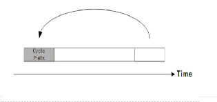
Interference caused by data symbols on adjacent subcarriers is referred to inter-carrier interference (ICI). Moreover, to reduce the ISI, a guard time is inserted at the beginning of each OFDM symbols before transmission as shown in Figure 1 and removed at the receiver before the FFT operation.
Figure1. Guard Time Insertion
If the guard time is chosen such that its duration is longer than the delay spread, the ISI can be completely eliminated.
2. Channel Estimation
The channel estimation can be performed by either inserting pilot tones into all of the subcarriers of OFDM symbols with a specific period or inserting pilot tones into each OFDM symbol. There are basically two types of classification of Channel estimation in OFDM
Pilot Based Channel Estimation: Known symbol
called pilots are transmitted.
Blind Channel Estimation: No pilots required. It
uses some underlying mathematical properties of
data sent.
In this paper we are going to study BER performance
evaluation of Pilot Based Channel estimation in OFDM. The Blind channel estimation methods are computationally complex and hard to implement. The Pilot based channel estimation methods are easy to implement but they reduces the bandwidth efficiency.
2.1 Pilot Symbol Assisted Modulation
Channel estimation usually needs some kind of pilot information [3] as a point of reference and this can be achieved by multiplexing pilot symbols into the data sequence, and this technique is called Pilot Symbol Assisted Modulation (PSAM).
2.2 Block Type Pilot based channel estimation
In this type, OFDM symbols with pilots at all subcarriers (referred to as pilot symbols herein) are transmitted periodically for channel estimation. Using these pilots, a time-domain interpolation [5] is performed to estimate the channel along the time axis. Since pilot tones are inserted into all subcarriers of pilot symbols with a period in time, the block type pilot arrangement [27] is suitable for frequency-selective channels.
2.3 Comb-Type Pilot channel estimation
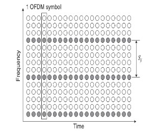
The comb –type pilot arrangement is suitable for fast-fading channels [2], but not for frequency-selective channels and are shown in the Figure.2
Figure2. Comb-type Pilot arrangement
2.2.1 Block Type pilot signal estimation
Channel can be estimated at pilot frequencies by two ways:
(LS) Estimation
(LMMSE) Estimation
For block type arrangements, channel at pilot tones can be estimated by using LS or LMMSE estimation, and assumes that channel remains the same for the entire block. So in block type estimation, we first estimate the channel, and then use the same estimates within the entire block.
2.3.1 Comb Type pilot channel estimation
To achieve high data rates as well as good performances, coherent detection is commonly used in most existing OFDM Systems. Coherent detection relies on knowledge of channel state information. One simple approach to obtain channel state information is to send some pilot symbols at the transmitter. Pilot subcarriers are often interlaced with data subcarriers. Comb-type pilot insertion has been shown to be suitable for channel estimation in fast fading channels. The channel estimation
IJSER © 2013 http://www.ijser.org
International Journal of Scientific & Engineering Research Volume 4, Issue 1, January-2013 3
ISSN 2229-5518
algorithm based on comb-type pilot is divided into pilot signal estimation and channel interpolation. Pilot signal estimation is based on LS or LMS criteria and interpolation algorithms include Linear Interpolation (LI), Second Order Interpolation (SOI), Cubic Spline Interpolation (CSI), Low Pass Interpolation (LPI) and DFT based interpolation.
2.2.1.1 Least Square Estimation (LSE)
The LS estimate [27] of the attenuations h, given the
received data Y and the transmitted symbols X is:
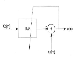
The LMS estimator uses a one-tap LMS adaptive filter at each pilot frequency. The first value is found directly through LS and the following values are calculated based on the previous estimation and the current channel output as shown in figure.3 e(m) is the error signal which is formed by taking the difference between the received pilot symbol Y P (m) and transmitted pilot symbol X P (m)


H X -1 y0 y1
0 1
… … … … … … . .

yN-1
N-1
(2)
2.2.1.2 Linear Minimum Mean Square Error Estimation
The linear minimum mean square error (LMMSE) estimate has been shown to be better than the LS estimate for channel estimation in OFDM systems based on block type [27] pilot arrangement. The minimum mean square error estimate block-type pilot channel estimation [27] is given by
-1
HLMMSE = Rpp {Rpp + an }
p (3)
Figure.3 Least Mean square Estimator
After pilot-symbol estimation, the data on the other sub-
2.3.1.1 Pilot Symbol Estimation in Comb Type (Least Square
estimator)
When ICI is eliminated by the GI, the received signal can be modeled with the following equation:
Y = XH+W …. (4) Where Y is the received signal vector, X is a diagonal matrix of the transmitted signal, least square estimator of OFDM signal is given by
HLS = ( XH X)-1 XHY……. (5) Since X is the diagonal matrix, the estimate is reduced to
HLS = X-1Y
This indicates that the LS Estimates of the frequency response channel is simply the division of the received signal by the transmitted signal. In comb-type OFDM channel estimation, the pilot sub-channel is first identified by using the transmitted pilot channel XP and received pilots YP the estimate of the channel at pilot sub-carriers is given by
HP (m) = Y P (m)/ X P (m)
m = , 1, 2…... N-1 …… (6)
2.3.1.2 Least Mean Square Estimator
channels is estimated by taking interpolation between the pilot sub-channel estimates.
3. Principle of Comb-Type OFDM Channel Estimation
For comb-type pilot subcarrier arrangement, the NP pilot signals, X P (m) where m=0, 1….N-1, are uniformly inserted into X(k). That is, all N subcarriers are divided into NP groups, each with L=N/ NP adjacent subcarrier. In each group, the first subcarrier is used to transmit the pilot signal. The OFDM signal modulated on the kth subcarrier can be expressed as
X (k) = X (mL + 1) = {X P (m) 1= 0
X d (m) 1= 1, 2, L-1 (16)
Each sub-channel transmits either a pilot symbols or a data
symbols, and is called pilot sub-channel, HP o a data sub- channel, Hd hence the channel response can be written as H (K) = H (mL+l) = { HP(m) l = 0
HP (mL + l), l = 1, 2 ……. L-1 (7)
Subsequently, the received pilot symbols and data symbols
can be expressed as
IJSER © 2013 http://www.ijser.org
International Journal of Scientific & Engineering Research Volume 4, Issue 1, January-2013 4
ISSN 2229-5518
Y P (m) = HP (m) X P (m) + IP (m) + N (m) (8) and
Y d (mL+1) = Hd (mL + l) Xd (mL+l) + Id (mL+l) + U (mL+l) (9)
Where, N (m) and U (mL+l) are the Gaussian noise in the pilot subcarrier
For coherent detection of the desired data symbol, the channel state information should be known a priori. In comb-type pilot aided OFDM System, channel state
information can be estimated by sending a sequence of pilot symbols. Generally, the process of comb-type pilot aided OFDM channel estimation has two major steps: pilot sub- channel identification and data sub-channel interpolation.
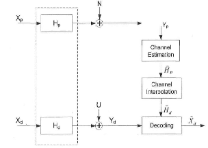
Figure.4 interpolation in comb type
3.1 Interpolation Technique in Comb-Type OFDM Channel
Estimation; LI (Linear Interpolation)
In the linear interpolation algorithm, two successive pilot subcarriers are used to determine the CIR for data subcarriers which are located between pilots. Using linear interpolation, the channel estimation at the data carrier k, where mL <k< (m+1) L, by is given by
Hd (k) = Hd (mL + l)
= {1-l/L} HP (m) + l/L HP (m+1)
= [HP(m+1) - HP(m)] l/L + HP 0 < l < L (10)
3.2 SOI (Second-Order Interpolation)
Theoretically, using higher-order polynomial interpolation will fit better than LI. However, the computational complexity grows as the order is increased. A piecewise second-order polynomial interpolation can be implemented as a linear time-invariant FIR filter.
The interpolation algorithm is given by
Hd (k) = Hd (mL + l) = C1HP (m-1) + C0 HP (m) + C-1HP (m+1) (11)
Where
C1 = α (α-1)/2
C0 =-(α-1) (α+1), and α = l/N
C-1= α (α+1)/2
The channel estimation at the data carrier k is calculated based on three channel estimates of the previous, present, and next pilot symbols. HP (m-1) is the channel estimate of the previous pilot symbol at position m-1, HP (m) is the channel estimate of the present pilot symbols at position m and HP (m+1) is the channel estimate of the next pilot symbol at position m+1.So the channel estimation for the first four data symbols of the first OFDM symbols is obtained using two pilot symbols as for the LI method.
3.3 CSI (Cubic Spline Interpolation)
In the CSI algorithm, the transfer function of each subcarrier is approximated by a third order polynomial with respect to l/L. Estimation is done by obtaining polynomial coefficients using four adjacent reference signals and their second order derivatives. In this case, given pilot points in one OFDM symbol, N-1 polynomials are obtained. A channel estimate for the data symbols between pilot symbols can then be obtained using these polynomials. The interpolation algorithm is given by
Hd (k)= A{l/L} HP (m) + B{l/L}HP (m+1) + C {l/L}z (m)+D{
l/L }z (m+1) ….. (12)
Where A {l/L}, B {l/L}, C {l/L} and D {l/L} are constants determined by l/L
Z (m) = HP (m) is the second derivative of the transfer
function of the mth reference signal.
3.4 LPI (Low-Pass Interpolation)
IJSER © 2013 http://www.ijser.org
International Journal of Scientific & Engineering Research Volume 4, Issue 1, January-2013 5
ISSN 2229-5518
The LPI method is performed by inserting zeros into the original sequence and then applying a low-pass finite- length impulse response (FIR) filter which allows the original data to pass through unchanged. This method also interpolates such that the mean-square error between the interpolated points and their ideal values is minimized.
3.5 DFT Based Channel Estimation
The DFT-based channel estimation [7] technique has been derived to improve the performance of LS or MMSE
channel estimation by eliminating the effect of noise outside the maximum channel delay. Let H [k] denote the estimate of channel gain at the k-th subcarrier, obtained by either LS or MMSE channel estimation method. Taking the IDFT [16] of the channel estimate:
IDFT {h[k]} = h[n] + z[n] n= 0, 1 … N-1 (13)
where z[n] denotes the noise component in the time domain. The coefficient for the maximum channel delay L as
hDFT [n] = { h[n] + z[n], n= 0,1 … L-1 (14)
0 otherwise
And transform the remaining L element back to the frequency domain as follows
HDFT [k] = DFT hDFT [n]
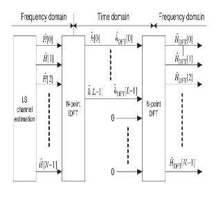
Figure.5 DFT based channel estimation.
After estimating the fading distortion due to the interpolation filter, this estimated channel transfer function is then transformed into the time domain by using IFFT.As a result, this transformed estimate can be regarded as the CIR and separated into two parts. The first part is located within the GI and contains the main energy of the CIR. The second part, which is outside the GI, is regarded as the noise components. Therefore zero values instead of noise components are inserted for the IFFT processing. As a result, the original transformed estimate within the GI plus these zero values are then transformed once more in the FD using an FFT to obtain a final CIR estimate without noise components.
4. Simulation and Results
In this paper, we used MATLAB 7.0 software for simulation for the Bit Error Rate (BER) performance of the different modulation techniques like BPSK and QPSK and 16QAM.
Figure.6 shows the least square estimation in block type and the BER performance of Block type pilot estimation using BPSK modulation has the best performance.
IJSER © 2013 http://www.ijser.org
International Journal of Scientific & Engineering Research Volume 4, Issue 1, January-2013 6
ISSN 2229-5518
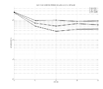
Figure6. Least Square Estimation in block
Figure 7 shows the implementation of least square estimation with different modulation ie BPSK, QPSK and QAM. In this graph as we seen LS estimation with BPSK has less Bit Error Rate as compared to the QPSK and 16
QAM. So there is less number of errors in case of BPSK
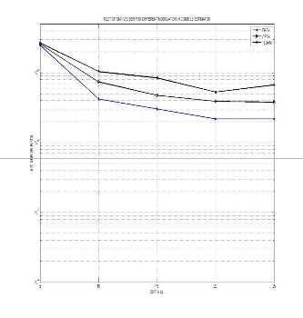
Figure7. Least Square Estimation in Comb type
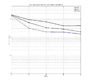
Figure8. Minimum Mean Square Error in block type
Figure.8 shows the Minimum mean square error estimation in block type and the BER performance of Block type pilot estimation using BPSK modulation has the best performance.
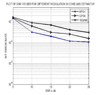
.Figure9. Least Mean Square Estimation in Comb type
Figure 9 shows the implementation of Least Mean Square Error estimation with different modulation ie BPSK, QPSK and QAM. In this graph as we seen LMS estimation with
IJSER © 2013 http://www.ijser.org
International Journal of Scientific & Engineering Research Volume 4, Issue 1, January-2013 7
ISSN 2229-5518
BPSK has less Bit Error Rate as compared to the QPSK and
16 QAM. So there is less number of errors in case of BPSK
Comparison between LS and LMS
Figure.10 shows the comparison between LS and MMSE in block Estimation. It has been observed that Minimum mean square error block type pilot channel Estimation has the better BER performance than the LSE
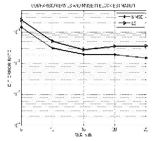
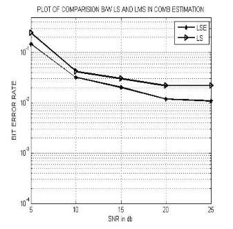
Figure11. Comparison between LS and LMS in Comb Type
Figure 11 shows the comparison between least square estimation and least mean square in case of comb channel estimation. As we seen in the graph the LMS has low bit error rate as compared to the LS estimation. Low bit error rate means there will be less numbers of errors. So LMS is the best technique as compared to the LS
DFT, LPI, CSI, SOI and LI using BPSK
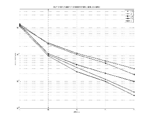
Figure10. Comparisons between LS and MMSE in Block
Estimation
Figure12. Implementation of different Interpolations using
BPSK
IJSER © 2013 http://www.ijser.org
International Journal of Scientific & Engineering Research Volume 4, Issue 1, January-2013 8
ISSN 2229-5518
Figure 12 shows the implementation of different interpolation i.e DFT based interpolation, Low pass interpolation, Cubic Spline interpolation, second order interpolation and linear interpolation using BPSK modulation. As seen in the graph the DFT based interpolation has low bit error rate. The best to worse interpolation as: DFT, LPI, CSI, SOI and LI.
DFT, LPI, CSI, SOI and LI using QPSK
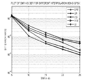
Figure13. Implementation of different interpolation using
QPSK
Figure 13 shows the implementation of different interpolation i.e. DFT based interpolation, Low pass interpolation, Cubic Spline interpolation, second order interpolation and linear interpolation using QPSK modulation as seen in the graph the DFT based interpolation has low bit error rate. The best to worse interpolation as: DFT, LPI, CSI, SOI and LI.
DFT, LPI, CSI, SOI and LI using 16 QAM
Table.1 All Simulation Parameters
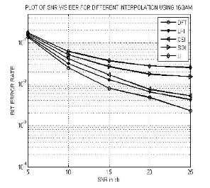
Figure14. Implementation of different interpolation using
16QAM
Figure 14 shows the implementation of different interpolation ie DFT based interpolation, Low pass interpolation, Cubic Spline interpolation, second order interpolation and linear interpolation using 16QAM modulation . As seen in the graph the DFT based interpolation has low bit error rate. The best to worse interpolation as: DFT, LPI, CSI, SOI and LI.
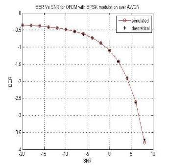
Simulation Result for OFDM with BPSK over AWGN
IJSER © 2013 http://www.ijser.org
International Journal of Scientific & Engineering Research Volume 4, Issue 1, January-2013 9
ISSN 2229-5518
[4] IEEE 802.11 Standard, “Wireless LAN Medium Access
Control (MAC) and Physical Layer (PHY) specifications,”
1999.
[5] H. Minn and V. K. Bhargava(2000), "An Investigation into Time-Domain Approach for OFDM Channel Estimation" IEEE Trans. on Broadcasting, Vol. 46, No. 1, pp.
240-248.
[6] M. Morelli and U. Mengali (2001), "A comparison of Pilot-Aided Channel Estimation Methods for OFDM Systems," IEEE Trans. on Signal Processing, Vol. 49, No. 12, pp. 3065-3073.
[7] P.-Y. Tsai and T. -D. Chiueh (2004), "Frequency-Domain Interpolation-Based Channel Estimation in Pilot-Aided OFDM Systems," IEEE 59th Vehicular Technology Conference (VTC'04), Vol. 1, pp. 420-424, Milan, Italy.
Figure15. BER Vs SNR for OFDM with BPSK over AWGN
Conclusion
In this paper, Channel Estimation based on comb type Pilot arrangement is presented and it is shown that this type of arrangement performs better when the channel is changing rapidly and block type has been used for the channels changing slowly. From the simulation results, it has been clear that if the length of the guard interval is chosen properly, then OFDM system exhibits robustness against multipath propagation, eliminates ISI and can be used for transmission at higher data rates. Simulation results also concluded that comb-type pilot based channel estimation with DFT interpolation performs the best among all other comb based channel estimation algorithms. In this article we have considered BPSK, QPSK and 16 QAM schemes and we found that BER performance of block type pilot estimation using BPSK modulation has the best performance. In comparison of LSE and MMSE, we calculated that MMSE block type pilot channel estimation has better performance than LSE.
References
[1] T.S.Rappaport (2009), “Wireless Communication”,
Prentice Hall.
[2] M. Hsieh and C. Wei (2002), “Channel estimation for OFDM systems based on comb-type pilot arrangement in frequency selective fading channels” in IEEE Transactions on Consumer Electronics, vol. 44.
[3] S. Coleri, M. Ergen, A. Puri and A. Bahai (2002), “Channel estimation techniques based on pilot arrangement in OFDM systems,” IEEE Trans. On Broadcasting, Vol. 48, No.3.
[8] A. Benzakour, S. Affes, C. Despins, and P.-M. Tardif (2004), "Wideband Measurements of Channel Characteristics at 2,4 and 5.8 GHz in Underground Mining Environments," Proc.of IEEE VTC'04-Fall, Los Angeles, California, USA, Vol. 5, pp. 3595-3599.
[9] M. Boutin (2004), “Statistical Modeling of a Radio
Propagation Channel in an Underground Mine at 2.4 GHz
and 5.8 GHz,” Master's Thesis, INRS-EMT, Montréal,
Canada.
[10] R. Steele (1992), “Mobile Radio Communications,” London, England, Pentech Press Limited.
[11] J. Heiskala, J. Terry (2002), “OFDM Wireless LANs: A Theoretical and Practical Guide,” Sams Publishing.
[12] C. Nerguizian, M. Djadel, C. Despins, and S. Affes
(2003), "Narrowband and Wideband Radio Channel
Characteristics in Underground Mining Environments at
2.4 GHz, " Proc. of IEEE PIMRC'03, Beijing, China, Vol. 1,
pp. 680-684.
[13] Yong Soo Cho, Won young Yang, “MIMO-OFDM
Wireless communication With Matlab”.
[14] Y. Li (2000), “Pilot-Symbol-Aided Channel Estimation for OFDM in Wireless Systems”, in IEEE Transactions on Vehicular Technology, vol. 49, no.4.
[15] Uma Shanker Jha, “OFDM Towards fixed and Mobile broadband wireless Access”.
[16] D. J. Young and C. Beaulieu (2000), “The generation of correlated Rayleigh random variates by inverse discrete Fourier transform,” IEEE Trans . on Communications , Vol.
48, No. 7.
[17] R. Prasad (2004), “OFDM for Wireless Communications
Systems,” Artech House, Boston- London.
[18] T. Roman, M. Enescu, and V. Koivunen (2003), "Time- domain method for tracking dispersive Channels in OFDM Systems," In Proc. of IEEE Veh. Technol. Conf., Vol.2, pp
1318-1321.
IJSER © 2013 http://www.ijser.org
International Journal of Scientific & Engineering Research Volume 4, Issue 1, January-2013 10
ISSN 2229-5518
[19] S. G. Kang, Y. M. Ha, and E. K. Joo (2003), "A comparative investigation on channel estimation algorithms for OFDM in mobile communications,'" IEEE Trans. on Broadcasting, Vol. 49, No. 2, pp. 142-149.
[20] R. Van Nee and R. Prasad (2000), “OFDM for Wireless Multimedia Communications, Artech House Publishers, Massachusetts.
[21] Richard Van Nee and Ramjee Prasad (2000), “OFDM for Wireless Multimedia Comunications. Artech House Publishers,”
[22] J Ae Kyoung Moon and Song In Choi (2000), “Performance of channel estimation methods for OFDM systems in multipath fading channels,”IEEE Trans. of Communication Electronics, vol. 46, pp. 161–170.
[23] Fredrik Tufvesson and Peter Hoeher (2000), “Channel Estimation using Superimposed Pilot Sequences,”IEEE Trans. on Communication.
[24] J.-J van de Beek, O. Edfors, M. Sandell, S.K. Wilson and P.O. Borjesson (1995), “ On channel estimation in OFDM systems” in Proc. IEEE 45th Vehicular Technology Conference, Chicago, IL, pp. 815-819.
[25] Jan-Jaap van de Beek. “On Channel Estimation in
OFDM Systems”.
[26] O. Edfors, M. Sandell, J.-J. Van de Beek, S. K. Wilson and P. O. Borjesson (1998), "OFDM channel estimation by singular value decomposition" IEEE Trans. Commun, pp.
931-939.
[27] Keshav kumar, Amit Grover (2012),”Comparison of Block Type Pilot Channel Estimation Techniques for Evaluating the Performance of OFDM”International Journal of Scientific & Engineering Research, volume , issue 11,pp.
1-9.
AUTHOR’S BIOGRAPHY
 The author place of birth is Banmankhi, Distt. Purnea, Bihar India on 15th, April 1989. Er. Keshav Kumar
is pursuing his Master of Technology in the area of
Electronics and Communication Engineering under the
supervision of Mr. Amit Grover, Assistant Professor, Department of Electronics and Communication Engineering, Shaheed Bhagat Singh State Technical Campus (Established by Govt. of Punjab) Moga road, Ferozepur, Punjab, India. Keshav Kumar received his B.Tech degree in the area of Electronics & Communication Engineering in 2011 From Baba Hira Singh Bhattal Institute of Engineering & Technology (Established by Govt. of Punjab) Lehragaga, Distt-Sangrur, Punjab, India. His area of interest includes Signal processing, MIMO systems, Wireless mobile communications, High speed digital communications and 4G Wireless communications.  Amit Grover (M’06-SM’09-PI’11&12) The author became a Member (M) of Association ISTE in 2006, a Senior Member (SM) of society SELCOME in September
2009, and a Project-In charge (PI) in august 2011 and in September 2012. The author place of birth is Ferozepur, Punjab, India on 27th, September 1980. The author received his M. Tech degree in Electronics and Communication Engineering from Punjab Technical University, Kapurthla, Punjab, India in 2008 and received his B. Tech degree in Electronics and Communication Engineering from Punjab Technical University, Kapurthala, Punjab, India in 2001. Currently, he is working as an Assistant Professor in Shaheed Bhagat Singh State Technical Campus, Ferozpur, Punjab, India. The email-id of corresponding author is amitgrover_321@rediffmail.com and his contact number is
+91-9988168581. His area of interest includes signal
processing, MIMO systems, Wireless mobile
communications, High speed digital communications and
4G Wireless communications.
IJSER © 2013 http://www.ijser.org
International Journal of Scientific & Engineering Research Volume 4, Issue 1, January-2013 11
ISSN 2229-5518
IJSER 2013
http://www.ijserorq