International Journal of Scientific & Engineering Research, Volume 6, Issue 5, May-2015 335
ISSN 2229-5518
Performance analyses of MHD Thruster using
CAE tools
Vikrant S Choudhary, Ujjal Kalita, Abhijeet Pratap, Mayur Randive
Abstract — MHD propulsion system is used for moving the vehicle in opposite direction of conducting fluid flow. The principle behind its propulsion is that it follows the flaming left hand rule of electromagnetism. The reaction force is used for propulsion. This paper reveals the analysis on velocity of thruster with some nozzle, by using 0.35T magnetic field strength. These analyses are done in the ANSYS 14.5 software by loading the MHD module. The analyses on velocity are done on three different nozzles such as divergent convergent nozzle, convergent divergent nozzle and throat divergent nozzle, by using same parameter. In these analyses we use salt water as a conducting fluid and the material for thruster is nickel alloys 200. The analytical and computational result indicated that the speed and performance increases proportionally with sea water conductivity. The comparison result shows that the convergent divergent nozzle produce good result as compare to other.
Index terms-- ANSYS, MHD thruster, Neodymium magnet, Nickel alloy 200, Nozzle, Propulsion, Salt water.
—————————— ——————————
1. INTRODUCTION
MHD thruster is a method for propelling vessel using only electric and magnetic field with no movable parts. Its main principle is that it involves electrification of the propellant (water) which can we guided by a magnetic field, pushing the vehicle in reverse direction. Here magneto means magnetic field, hydro means liquid and dynamics means movement. Its main function is that magnetic or electric fields induce currents in moving conductive fluid. These create forces on the liquid fluid. 80% of the electricity produced in the world is HYDRAL and the remaining is produced from non-conventional sources [1].
MHD power generation is new system of electric power generation which is said to be high efficiency and less pollution as compare to other sources. Purpose of MHD generator is to convert heat energy released by the fuel directly to electric energy without a traditional electric generator.
Figure 2 : MHD generation
Figure 1 : Magneto-hydrodynamic propulsion principle
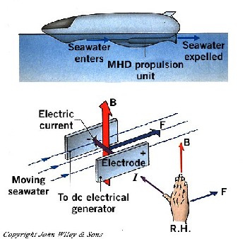
MHD thruster produce magnetic field by passing through an electric current through liquid conductor or salt
water. In the year 1832 Michael Faraday had done experiments on Magneto Hydro Dynamic (MHD) Electrical Power Generation [2]. In 1990, Mitsubishi built many prototypes of ships which is propelled by MHD thruster. These ships reached the speed of 15 km/h. After that japan started its sea trials on the magnetic ship .Yamato 1 is propelled by two MHD thrusters, which gained the speed more than 200 km/h with little noise. Ezzat D Doss Et al [3] gave advantages of MHD seawater propulsion over mechanical propellers. According to them due to the absence of mechanical propeller system in the ship there will be reduction in the vibration level, which reduce the mechanical noise which is generated by the propeller. Also the speeds of
IJSER © 2015 http://www.ijser.org
International Journal of Scientific & Engineering Research, Volume 6, Issue 5, May-2015 336
ISSN 2229-5518
MHD seawater vehicle are not affected by any physical restriction. MHD thruster concept offers easier maintenance because of no moving parts and as a result makes the vessel undetectable by sonar radars. Abdollahzadeh Et Al [4] considered transient, hydro-dynamically and thermally fully- developed laminar flows in an incompressible fluid between two parallel plates. Perspective of flow/fight control methods of high speed flights in upper atmosphere based on a wide varity of MHD and momentum conservation technique as
Which is equal to :
We know that:
F = A ∙ ρ ∙ h ∙ g [6]
v = A ∙ h [7]
F = v ∙ ρ ∙ g [8]
m = v ∙ ρ [9]
discussed by Bityurin Et Al [5].
In this study we are using DC current to generate the
electromagnetic current. The advantage of MHD flight control
are associated with extended interaction region including the gas dynamically undisturbed upsteam flow. The MHD flow comtrol system under consideration consists of two main components: a magnet system that provide the desirable level of magnetic induction in the interaction region and MHD generator repersent by an electrode system installed on vehicle upsteam surface.
Three types of MHD thruster are generally available.
Inner ducting type: it is a thruster duct which is installed in
the lower part of swath which increases the speed of the sea
water for generating thrust force.
Annular ducting type: they are composed of several segments
which are fitted in the surrounding of the lower half of the swath.
Pod mount type: In this case two pods of thrusters are
installed on both sides of the lower half of swath. Shinsuke AKAGI Et Al [6] did research on these three kinds of thruster system.
2. MATHEMATICAL FORMULATION OF MHD THRUSTER
For MHD thruster model or prototype, we need to calculate some forces such as thrust force, Lorentz force, and general thruster equation.
2.1 Thrust Force
Mass of the liquid displaced upward thrust force:
F = m ∙ g [10]
That is the weight of the liquid displace.
2.2 Lorentz Force
The Lorentz force law states that the charged particle experience a force when is moving in the electromagnetic field. This force can be explained as
F= Q (v x B) [11] Where,
F is the force acting on charged particle.
Q is the charge of the particle
V is the velocity of particle
B is the magnetic induction
2.3 Thruster Equation
For jet propulsion, linear momentum equation is:
�P⃗ = m ∙ v�⃗ [12]
Whereas:
�v⃗ = jet velocity of thruster device
m = mass
�p⃗ = pulse, momentum
Thruster force equation:

F�⃗ = ṁ ∙ v�⃗ = 3�4 ∙ w 2 ∙ |s⃗| ∙ ρ ∙ s� [13]
For collinear thruster with perfect efficiency:
ρ =density of the liquid.
P1 = lρg [1]
For real thruster:

F = 3�4 ∙ w 2
∙ s ∙ ρ
[14]
g =gravitational force.
P2 = (l + h) ∙ ρ ∙ g [2]

F�⃗ = 3�4 ∙ η2 ∙ w 2 ∙ |s⃗| ∙ ρ ∙ s� [15]
Downward force acting on the upper phase of the body:
F1 = P1 × A = l ∙ ρ ∙ g × A [3]
F2 = (l + h) ∙ ρ ∙ g ∙ A [4]
Net thrust force acting on the body, than subtract (4) to (3).
F = F2 − F1 [5]
This equation helps in making better and efficient thruster and also some engine depending on ion propulsion.
3. DESIGN OF MHD THRUSTER
This geometry of the nozzle done with the help of Creo 3D software in which the divergence and convergence nozzle are made. In which the two magnets are attached at the center part of the nozzle that shown in the figure below, the different
IJSER © 2015 http://www.ijser.org
International Journal of Scientific & Engineering Research, Volume 6, Issue 5, May-2015 337
ISSN 2229-5518
view of the nozzle are shown. This model of nozzle shows that the actual arrangement of the MHD thruster.
Figure 3 : Geometry of thruster
Here the total length of convergence divergence nozzle is
100mm, inlet and outlet diameter is 20mm, the taper angle is
450, and the internal diameter is 10mm.
Model 3: Throat divergent nozzle
Here the total length of throat divergence nozzle is 100mm, the inlet diameter is 30mm, the taper angle is 450, the outlet diameter is 10mm.
In all the cases the inlet velocity is taken as 1 m/s and magnetic strength of the magnet is 0.35 Tesla i.e. 3500 Gauss. Here analysis is performed for determining the pressure variation and velocity variation inside the nozzle. These analyses are performed in ANSYS and the results are shown in table.
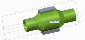
Figure 4 : 3D View of thruster after rotating
We are analysis on three different nozzles in ANSYS
14.5.computatonal analyses are done after loading the MHD
module in Ansys 14.5. The magneto hydrodynamic (MHD) module is provided as an additional module with the standard ANSYS FLUENT license software. This module is loaded, when the meshing is done and setup file is open than click on the models the window opened but there is no MHD module. The ANSYS FLUENT MHD model allows analyzing the behavior of electrically conducting fluid flow under the influence of constant (DC) or oscillating (AC) or electromagnetic field. The externally imposed magnetic field may be generated either by selecting simple built in function or by importing a user supplied data file. Equation of MHD are solved through user define scalar transport equation. MHD module is relatively new and some computing limits and other parts will we added in upgrade version.
4. RESULT AND DISCUSSION
Model 1: Divergent-Convergent nozzle
Here the total length of divergence convergence nozzle is
100mm, inlet and outlet diameter is 10mm, the taper angle is
450, and the internal diameter is 20mm.
Model 2: Convergent-Divergent or D-Laval nozzle
Table 1 : Velocity variation table
Type of nozzle | Velocity inlet(m/s) | Velocity outlet(m/s) |
Divergent- Convergent | 1 | 1.225 |
De-Laval | 1 | 4.3978 |
Throat divergent | 1 | 4.3937 |
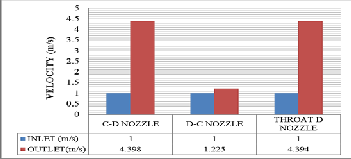
Figure 5 : Velocity variation chart of nozzles
Here it is found that for constant inlet velocity, there is variation in outlet velocity and the velocity at the outlet for De-Laval nozzle is maximum.
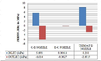
Table 2 : Pressure variation table
IJSER © 2015 http://www.ijser.org
International Journal of Scientific & Engineering Research, Volume 6, Issue 5, May-2015 338
ISSN 2229-5518
Figure 6 : Pressure variation chart of nozzles
This table shows the maximum and minimum pressure produced in the nozzle. Here maximum pressure is produce at inlet and minimum pressure is produce at outlet i.e. the velocity increases at outlet.
5. CONCLUSIONS
The velocity of the nozzle depends on different parameters i.e. diameter of nozzle, magnetic strength of magnet and the length of the nozzle. In the divergence convergence nozzle, the diameter of the nozzle initially increases till throat after this the diameter reduces. In case of De-Laval nozzle the diameter initially decreases and then increases. Again in throat divergent initially diameter decreases and then it remains constant. From all the analyses it is found that for constant flow from the inlet, the outlet velocity varies according to nozzle. It is found that De-Laval nozzle exhibits maximum velocity at the outlet. Thus it can be concluded that De-Laval nozzle will be the most effective nozzle that can be used as MHD Thruster.
REFERENCES
[1] Vishal. D.Dhareppagol & Anand Saurav, “The Future Power Generation with MHD generators Magneto hydrodynamic generation”, ISSN: 2278-8948, Volume-2, Issue-
6, 2013.
[2] P. F. Sens, Commission of the European Communities. Brussels. Belgium, “Coal-fired magneto hydrodynamic (MHD) book of electric power generation”, 1992.
[3] Ezzat D. Doss and Howard K. Geyer, “An Overview of MHD Seawater Thruster Performance and loss Mechanisms”, Cass Avenue Argonne, Illinois 60439 U.S.A.
[4] M.Y.Abdollahzadeh Jamalabadi, “Analytical Study of Magneto-hydro-dynamic Propulsion Stability” J. Marine Sci. Appl., 13: 281-290,2014.
[5] V.A.Bityurin, A.N.Bocharov (IVTAN, Mosow), J.T.Lineberry (LyTee LLC, Tullahoma, TN, USA), “MHD AROSPACE APPLICATIONS”.
[6] Shinsuke AKAGI, Kikuo FUJITA and Kazuo SOGA, “Optimal Design of Thruster System for Superconducting Electromagnetic Propulsion Ship”, May 24-27, Delft, the Netherlands, 1994.
IJSER © 2015 http://www.ijser.org