International Journal of Scientific & Engineering Research Volume 2, Issue 9, September-2011 1
ISSN 2229-5518
Performance Investigations on DWDM-OADM Optical Ring Network for CRZ Data Format at Different Fiber Length
Sarbjit Singh, Love Kumar
single mode fiber at data rates of 10 Gbps for CRZ data format has been reported. The performance of the system is reported on the basis of eye diagram, optical OSNR, optical power and noise power. It is reported that the variation of OSNR at wavelength 1.5550 nm is 2.5868,
2.5125 and 2.5399 dB at fiber length of 50, 75 and 100 km and maximum variation at wavelength 1.5528 nm is 9.0459, 9.3128 and 9.1299 dB at fiber length 50, 75 and 100 km.
—————————— ——————————
information signal is generally referred to as homodyne crosstalk [8].
ue to increase in bandwidth demand in the field of
network the use of optical fiber is recommended. To
achieve the higher data rate to support new multimedia application and services different network providers are moving towards optical network. Optical networks, based on the optical fibers provide higher data rate and reduced the cost of the bandwidth starving application such as the video and multimedia services and interaction etc [1]. Therefore, Dense Wavelength Division Multiplexing (DWDM) technology is developed to support tremendous bandwidth. Recently, the channel bandwidth of commercial DWDM system has reached to OC-192 and the total bandwidth of an optical network exceed 20 Tbps [7]. The term “dense” WDM or DWDM, was once used to signify the use of wavelengths with a channel spacing of 50 GHz in a single
mode fiber system (SMF) [1].
Optical Add/Drop Multiplexer (OADM) is an important
network element in DWDM-OADM system that can be used to reduce the number of conversions between the electrical and optical domains and frame processing time, thus decreasing the delay of the network. An OADM takes a multi-wavelength signal arriving in an input fiber, drops one or more preselected wavelengths from the signal, and adds one or more pre- selected wavelengths into the multi-wavelength signal that exits in an output fiber. An OADM may be well thought-out to be a certain type of optical cross-connect [2].
————————————————
Sarbjit singh is currently pursuing masters degree program in electronics communication engineering in DAV institute of engineering & technology, Jalandhar, Punjab, INDIA, PH-0972103329.
E-mail: hometheaterworld@mail.com
Love kumar is currently A.P in electronics communication engineering in
DAVIET, Jalandhar, Punjab, E-mail: er.lovekumar@gmail.com
The main factor in OADM is crosstalk which arises due to component imperfections and limits the performance of the system. Optical crosstalk at the same wavelength as the
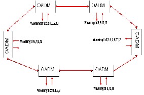
In the optical network, the signal riding on one of the wavelength channels may originate at one edge, in the network and leave the network at any other point. Along any particular route in the network, that wavelength may pass through several optical network elements such as OXCs and OADM [3].The proposed network architecture is based on a single unidirectional fiber ring topology having data rates of 10 Gbps. It consists of six OADM nodes as shown in fig. 1 connected by non linear single mode fiber. Each node is converting the electrical data into the optical signal and transmitted the optical link of DWDM ring. Each node is also equipped with tunable transmitter operating in multiband environment and compound receiver with multiple filters; each receiver takes care of a particular data channel which owns a unique specific wavelength.
Fig. 1. Network architecture of DWDM-OADM ring network
Each node has the ability to access any wavelength of each data channel. EDFA (erbium doped fiber amplifier) after each fiber span is inserted to compensate the fiber attenuation. The power per channel of -9 dBm was used at transmitters. We used 12
IJSER © 2011
International Journal of Scientific & Engineering Research Volume 2, Issue 9, September-2011 2
ISSN 2229-5518
wavelengths at 50 GHz spacing ranging from 1550 to 1544 nm
wavelength. After each node multiplot is used to observe optical performance matrix. Time delay block is used to connect signal form last node back to first node for performing ring simulation with multiple iterations. The Simulation setup for DWDM-OADM optical ring network has been shown in fig.2. Each OADM node has one input and one output for line signal (in- and out-transport interfaces), and also 12 inputs/outputs for added/dropped wavelengths (in- and out- clients interfaces) as shown in fig.3. The random data block generate the pseudo random bits which are change into electrical signals and then converted into 1550 nm optical signal to be transmitted as shown in fig 3. Output from these ports are connected to optical receiver blocks and then to MultiPlot visualizer which provide plots for electrical signal spectrum, and eye diagram.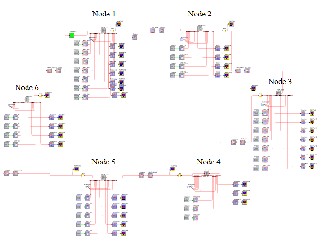
Fig. 2. 12-Wavelength DWDM-OADM Optical Network Simulation setup
Each node is consisting of demultiplexer and multiplexer which work in multiband environment. The optical multiplexer and demultiplexer are used to combines the add signal from the current node and to drop signal from current node which arrived from the other neighboring downstream node. The OADM Node block consists of one 1x12
Demultiplexer, 12x1 Multiplexer, and 12 optical switches as shown in fig.3. The input from transport interface (Input1) is demultiplexed into 12 wavelengths and each of them goes to a switch with corresponding input from client interface (Input2- Input13). The switch can be in either bar or cross state (is set by the switching array value). One output from the switch goes back to clients interface out ports (Output2-Output13) and the other output is being multiplexed with 11 other outputs and then sent to transport interface output (Output1). The OADM CC block can specify following parameters: crosstalk level [ -30
dB], switching configuration [1,1,1,1,1,0,0,0,1,1,0,0], first
channel wavelength [1.55E-6] and channel spacing [4.0E-10], optical filter bandwidth [3.2E-10] used in demultiplexing.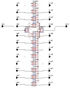
Fig. 3. Internal Architecture of OADM Node
The performance of DWDM-OADM optical ring network is reported on the basis of eye diagram, OSNR, Optical Power and Noise Power at different fiber lengths. The slope of eye diagram determines how sensitive the signal is to timing error. A smaller slope allows eye to be opened more and hence less sensitivity to timing error [7]. The width of the crossover represents the amount of jitter present in the signal. With all these methods it becomes very easy to distinguish between two eyes at different fiber length. The fig. 4, 5 and 6 shows the eye pattern for channel 1 (1.5550 nm) for CRZ data format at fiber lengths 50, 75 and 100 km respectively. It has been observed that the eye diagram of the system changes as fiber length increases.
IJSER © 2011
International Journal of Scientific & Engineering Research Volume 2, Issue 9, September-2011 3
ISSN 2229-5518
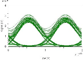
Fig. 4. Eye diagram of wavelength 1 at fiber length of 50 km
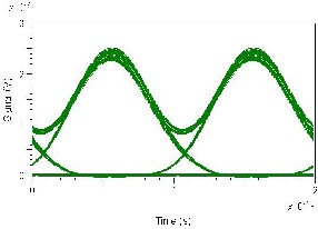
Fig. 5. Eye diagram of wavelength 1 at fiber length of 75 km
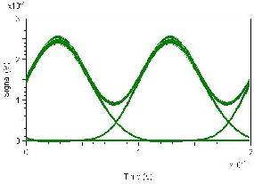
Fig. 6. Eye diagram of wavelength 1 at fiber length of 100 km
Fig. 7, 8 and 9 represent the eye diagram of middle channel 8 at wavelength 1.5528 nm for CRZ data format at fiber length 50,
75 and 100 km. It has been observed that the eye opening of the system changes with increase in fiber length and results in more sensitivity to timing errors.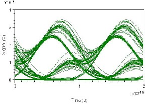
Fig. 7. Eye diagram of wavelength 8 at fiber length of 50 km
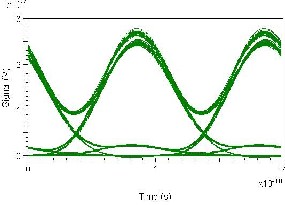
Fig. 8. Eye diagram of wavelength 8 at fiber length of 75 km
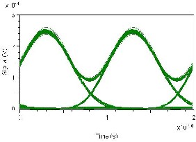
Fig. 9. Eye diagram of wavelength 8 at fiber length of 100 km
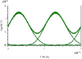
Fig. 10, 11 and 12 represent the eye diagram of channel 12 at wavelength 1.5544 for CRZ data format at fiber length 50, 75 and 100 km. It has been observed that the eye opening of the system changes due to crosstalk and span loss and results in more sensitivity to timing errors.
IJSER © 2011
International Journal of Scientific & Engineering Research Volume 2, Issue 9, September-2011 4
ISSN 2229-5518
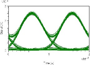
TABLE 1
SNR at different fiber lengths
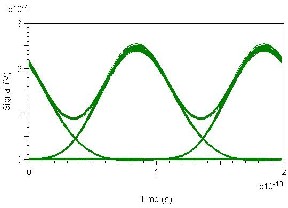
. Fig. 10. Eye diagram of wavelength 12 at fiber length of 50 km
Fig. 11. Eye diagram of wavelength 12 at fiber length of 75 km
The fig.13 represents the OSNR values for the wavelength
1(1.5550 nm) is 2.5868, 2.5125 and 2.5399 dB at fiber length of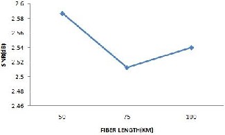
50, 75 and 100 km. The values of the systems are varying with change in fiber distance as tabulated in table 1.
Fig. 12. Eye diagram of wavelength 12 at fiber length of 100 km
The OSNR values for the DWDM-OADM optical ring network
for CRZ data format has been tabulated in table 1. It has been
analyzed that OSNR vary with increase fiber length as well as wavelength of the system. It has been observed that the OSNR of the system at 1.5550 nm wavelength is 4.9192, 4.0744 and
2.9736 dB for fiber length 50, 75 and 100 km. The OSNR observed at Wavelength 1.5528 is 2.6454,-1.7751 and 2.8296 dB for fiber length of 50, 75 and 100 km.
Fig. 13. SNR of wavelength1 at different fiber length
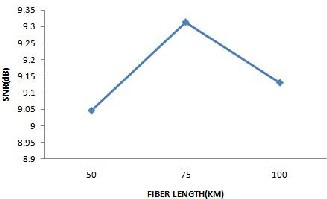
The fig.14 represents the OSNR at middle wavelength 1.5528 nm is 9.0459, 9.3128 and 9.1299 dB at fiber length 50, 75 and 100 km is due the nonlinearity of the fiber and crosstalk of the system. Maximum effect of crosstalk has been observed at middle channel of the system.
IJSER © 2011
International Journal of Scientific & Engineering Research Volume 2, Issue 9, September-2011 5
ISSN 2229-5518
Fig. 14. SNR of wavelength 8 at different fiber length
The fig.15 represents the OSNR values for the wavelength
12(1.5544 nm) is 2.7515, 2.7469 and 2.7260 dB at fiber length 50,
75 and 100 km.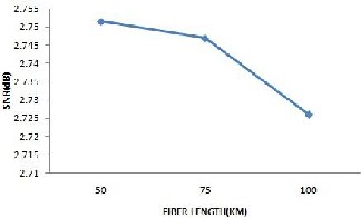
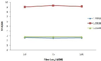
Fig. 15. SNR of wavelength 12 at different fiber length
Fig. 16. SNR of different wavelengths at different fiber length
The fig.16 represents the comparison of OSNR of wavelength
1.5550, 1.5528 and 1.5544 nm at fiber length 50, 75 and 100 km. The first and last wavelength shows very less variation in its SNR. The maximum variation is at mid wavelength due to crosstalk and nonlinear property of fiber.
The noise power of DWDM-OADM ring network for each
and every channel at different fiber length is tabulated in table
2. The optical noise power for wavelength 1(1.5550 nm) is
1.6359, 1.0797 and 1.0076 W at fiber lengths 50, 75 and 100 km. The variation of noise power at wavelength 8(1.5528 nm) is
1.4807, 9.6666 and 9.0131 W at fiber length 50, 75 and 100 km. These values have very less variation in top and bottom wavelength. The variation is in mid wavelengths due to nonlinearity in the fiber and crosstalk of the system.
TABLE 2
OPTICAL NOISE POWER AT DIFFERENT FIBER LENGTHS
WAVELENGTH (nm) | Optical Noise Power (w) | |||
WAVELENGTH (nm) | 50 km | 75 km | 100km | |
1. | 1.5550 | 1.6359 | 1.0797 | 1.0076 |
2. | 1.5504 | 1.6643 | 1.0786 | 1.0065 |
3. | 1.5508 | 2.8890 | 1.6644 | 1.4914 |
4. | 1.5512 | 1.5142 | 1.0676 | 1.0007 |
5. | 1.5516 | 1.4972 | 1.0629 | 9.9637 |
6. | 1.5520 | 2.2982 | 1.5544 | 1.4820 |
7. | 1.5524 | 2.8779 | 1.6609 | 1.4912 |
8. | 1.5528 | 9.4807 | 9.6666 | 9.0131 |
9. | 1.5532 | 3.1230 | 1.8670 | 1.6779 |
10. | 1.5536 | 1.6300 | 9.6657 | 8.6715 |
11. | 1.5540 | 1.6122 | 9.5602 | 8.5769 |
12. | 1.5544 | 2.1243 | 1.4556 | 1.3619 |
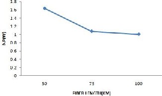
The fig.17 represents the optical noise power for the wavelength 1(1.5550 nm) is 1.6359, 1.0797 and 1.0076 W at fiber length 50, 75 and 100 km. The Noise Power of the systems is varying with change in fiber distance as tabulated in table 2. The fig.18 represents the optical noise power at middle wavelength 1.5528 nm is 9.4807, 9.6666 and 9.0131 W at fiber length 50, 75 and 100 km. The fig.19 represents the optical noise power at wavelength 12 (1.5544 nm) is 2.1243, 1.4556 and
1.3619 W at fiber length 50, 75 and 100 km. The variation is in mid wavelengths due to crosstalk and nonlinearity of the fiber.
IJSER © 2011
International Journal of Scientific & Engineering Research Volume 2, Issue 9, September-2011 6
ISSN 2229-5518
The fig.20 represents the comparison of optical noise power of wavelength 1.5550, 1.5528 and 1.5544 nm at fiber length 50, 75 and 100 km. The first and last wavelength shows very less variation in its noise power. The maximum variation is observed at mid wavelength due to crosstalk and nonlinearities of fiber.
Similarly table 3 represents the optical powers at different fiber lengths.
TABLE 3
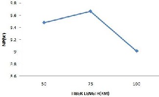
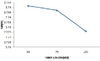
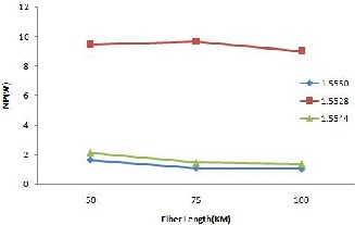
Fig. 17. Noise Power of wavelength 1 at different fiber length Fig. 18. Noise Power of wavelength 8 at different fiber length Fig. 19. Noise Power of wavelength 12 at different fiber length
Fig. 20. Noise power of different wavelengths at different fiber length
OPTICAL POWER AT DIFFERENT FIBER LENGTHS
WAVELENGTH (nm) | Optical Power (w) | |||
WAVELENGTH (nm) | 50 km | 75 km | 100km | |
1. | 1.5550 | 9.1736 | 7.6690 | 7.9672 |
2. | 1.5504 | 1.1783 | 7.4357 | 7.6602 |
3. | 1.5508 | 2.6750 | 7.2923 | 2.8255 |
4. | 1.5512 | 8.0741 | 7.9609 | 7.9441 |
5. | 1.5516 | 7.9364 | 7.9439 | 7.9434 |
6. | 1.5520 | 4.5749 | 4.1397 | 4.1673 |
7. | 1.5524 | 5.9218 | 4.3120 | 4.3116 |
8. | 1.5528 | 7.4319 | 7.1638 | 7.1809 |
9. | 1.5532 | 5.9688 | 4.6494 | 4.6408 |
10. | 1.5536 | 9.5285 | 7.3801 | 7.5991 |
11. | 1.5540 | 7.1758 | 7.7130 | 7.6818 |
12. | 1.5544 | 5.3381 | 4.2430 | 4.1604 |
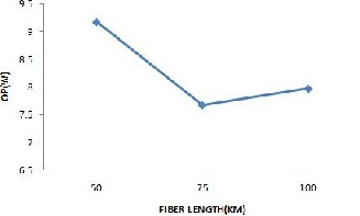
Fig. 21. Optical Power of wavelength 1 at different fiber
Length
The optical power for wavelength 1(1.5550 nm) is 9.1736,
IJSER © 2011
International Journal of Scientific & Engineering Research Volume 2, Issue 9, September-2011 7
ISSN 2229-5518
7.6690 and 7.9672 W at fiber lengths 50, 75 and 100 km as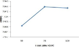
represents in fig. 21.
The fig.24 represents the comparison of optical power of
wavelength 1.5550, 1.5528 and 1.5544 nm at fiber length 50, 75 and 100 km.
22. Optical Power of wavelength 8 at different fiber length
Fig.
It has been concluded that the timing error of the system is
increases as we increase the fiber length in the DWDM-OADM optical ring network for CRZ data format. For non linear fiber the OSNR of the system reduced at middle wavelength due to the nonlinear effect of optical fiber and crosstalk of the system. It has been observed that the values of OSNR for the wavelength 1(1.5550 nm) is 2.5868, 2.5125 and 2.5399 dB at fiber length 50, 75 and 100 km. The value of OSNR at middle wavelength 8 (1.5528 nm) is 9.0459, 9.3128 and 9.1299 dB at fiber length 50, 75 and 100 km. The values of OSNR for the
The variation of optical power at wavelength 8(1.5528 nm) is
7.4319, 7.1638 and 7.1809 W at fiber length 50, 75 and 100 km as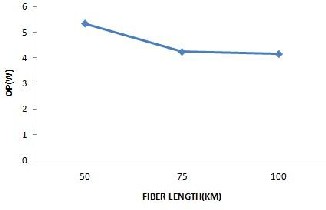
represents in fig. 22.
wavelength 12(1.5544 nm) is 2.7515, 2.7469 and 2.7260 dB at fiber length 50, 75 and 100 km. It has been observed that the noise power of the system is almost similar for the first and last channel and maximum variation reported at middle channel
15528 nm is 9.4807, 9.6666 and 9.0131 W at fiber length 50, 75
and 100 km.
23. Optical Power of wavelength 12 at different fiber length
Fig.
[1] R D Rallison, Ralcon corp, “Dense Wavelength Division Multiplexing DWDM and the Dickson Grating”, Wasatch Photonics, AUG-2001
[2] Yuefeng Ji; Jie Zhang; Yongmei Sun; Wanyi Gu; Bing Ye; Yong Zhao, “Research and realization of OADM technology in metro optical network” Proceedings Vol. 453, Metro and Acess Networks, Wanyi Gu; Jianhui; Jin-Yi Pan, Editors, pp.159-170, Publication: SPIE.org, 16 oct 2001
[3] Mohammad Syuhaimi Ab-Rahman, “Survivability Schemes in
Optical Cross ADD and Drop Multiplexer ” Feb. 17-20, 200,
The fig.23 represents the optical power at wavelength 12
(1.5544 nm) is 5.3381, 4.2430 and 4.1604 W at fiber length 50, 75 and 100 km.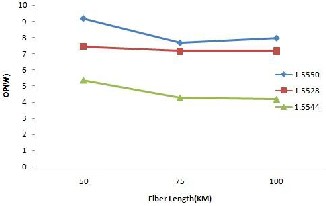
Fig. 24. Optical power of different wavelengths at different fiber length
ICACT2008
[4] P. Ferreira and B. Cossa “Testing the Scaliability of DWDM networks” 4th International Conference on technology policy and innovation, Curitiba, Brazil, August 28-31, 2000
[5] Jorg B.Micheei “lambda MON-A Passive Monitoring Facility for DWDM Optical Networks”U.S. National Science Foundation Collaborative Agreement ANI-0129677 (NLANR/MNR, 2002), New Zealand
[6] Kazem A. Sohraby, Mohammad T. Fatehi, Victor B. Lawrence, Mark R. Wilson, “Network Architecture for an All-Optical Internet” NFOEC 2000 Technical Proceedings, VOL. 1, August 27-
31, Denver, CO, pp. 568-577
[7] M.Ifran Anis, Naveed Ahmed, Usman Ahmed “ Performance Analysis Of Optical Network Based on OADM by using Different Filters” . IEEE, 978-1-4244-4740-4/09, 2009.
[8] M.Mahiuddin and M.S Isham “Incoherent Crosstalk Analysis in Fiber Bragg Grating Based Optical Add/Drop Multiplexer in Optical Network” 6th International Conference on Electrical and Computer Engineering ICECE 2010.
IJSER © 2011
International Journal of Scientific & Engineering Research Volume2, Issue 9, September-2011 8
ISSN 2229-5518
IJSER !b) 2011