Inte rnatio nal Jo urnal o f Sc ie ntific & Eng inee ring Re se arc h, Vo lume 3, Issue 1, January -2012 1
ISS N 2229-5518
Parametric influence on cutting parameters characteristics in precision machining of ceramic coating materials
PROF. MOHAMMED YUNUS, DR.J. FAZLUR RAHMAN
Abstr act— Ceramic coated components have the advantage f eatures of both metal and ceramics, i.e. good t oughness, high hardness and w ear resistance. Despite their outstanding characteristics, ceramic materials are not used in many cases due to high cost of machining. A major draw back to engineering applications of ceramic is due to their brittleness and f rac ture toughness, w hich makes them diff icult and costly to machine.
In order to study the precision machining processes of ceramics like grinding and lapping, experiments w ere conducted to f ind out the in- f luence of various cutting parameters on surf ace quality production as w ell as grinding and lapping performance.
Surface grinding of ceramic coating materials w as done on samples specimens coated w ith Alumina (Al2O3), Alumina - Titania (Al2O3- TiO2) and Partially stabilized zirconia (PSZ )using diamond and CBN (cubic boron nitride) grinding w heels. Based on the experimental r e- sults, the inf luence of cutting parameters, namely, cutting f orce, surf ace roughness and bearing area characteristics w ere ev aluated and optimu m machining conditions have been suggested for better perf ormance in precision machining of ceramic coating materials.
Inde x Terms— Bearing Area Characteristics, Cutting f orce, Diamond and CBN grinding w heel, Grinding and Lapping, Optimizations of
Cutting parameters, Precision Machining Processes Surf ace roughness.
—————————— ——————————
1 INTRODUCTION
ITH the projected wide spread applications of ceramic coating materials, it is necessary to develop an appro- priate technology for their efficient and cost effective
machining processes[5],[7], [9] and [11 ]. Grinding of c eramics
is a difficult task, as it is generally associated with cracking, splintering and delamination of surfaces. Conventional processes and tools are not generally suited for the machining of ceramics. Standard machining tools can be used with opti- mization of machining parameters in operating conditions [
13-14 ]. Various precision machining techniques that could be
adopted for efficient machining of cera mic materials, namely grinding and lapping processes are studied in detail for the parametric influence of various cutting parameters of prec i- sion machining of ceramic coating materials.
Ceramic coated components used in industrial applica-
tions, generally require post treatments like heat treatment
and surface finishing by precision machining [1-8]. Good sur- face finish and high efficiency in machining to meet the d e- mands of tight tolerances are generally achieved by grinding, lapping and polishing like precision machining processes [3].
Grinding of ceramics is a difficult task, as it is generally associated with cracking of surface. In order to study the
———— ——— ——— ——— ———
Mr.Mohammed Yunus is currently pursuing Ph.D. degree program inMa- terial engineering inAnna University of Technology, Professor,HKBKCE, Bangalore, India, PH-00919141369124. E- mail:yunus.mohammed@rediffmail.com.
Dr.J.Fazlur Rahaman, is Professor Emeritus in Mechanical engineering in
H.K.B.K.C.E (affliated to Visweswaraiah Technological University, Bel-
gaum), Bangalore, India, PH -00919845350742.
E-mail:jfazlu2003@yahoo.co.in
effect of precision measuring processes [15], experiments were conducted to check the machining parameters like surface quality, grinding forces etc. on ceramic coated components for different machining conditions.
The main object of this s tudy is to evaluate the behavior of A, AT, PSZ, Super-Z a lloy and ZTA cera mic coating materia ls s ub- jected to different grinding conditions . The performance was ev a- luated by machining grinding force [20-22], s urface finis h [17] and bearing area characteris tics [18] and als o oil film retainability characteris tics [15].
2 EXP ERIM ENTAL PROCEDURE
Three different commercially available ceramic coating powd- er materials namely, Alumina (Al2O3), Alumina-Titania (Al2O3-TiO2), Partially Stabilized Zirconia (PSZ) were used for the preparation of coatings [10-14]. A 40 KW Sulzer, Metco plasma spray system with 7MB gun is used for this plasma spraying of coatings. Mild steel plates of 50x50 x6 mm were used as substrate to spray the ceramic oxides. They were grit blasted, degreased and spray coated with a 50 to 100 microns Ni Cr Al bond coat. The above ceramic materials were then plasma sprayed using optimum spray parameters.
2.1 Precision Machining of Ceramic Coating
Grinding: Using diamond and CBN grinding wheels [20] with the surface grinding trials were conducted with the grinding conditions mentioned below in table 1. Machining trials were conducted on different ceramic coated specimens (A, AT and PSZ ceramic coatings).
IJSER © 2012
http :// www.ijser.org
Inte rnatio nal Jo urnal o f Sc ie ntific & Eng inee ring Re se arc h, Vo lume 3, Issue 1, January -2012 2
ISS N 2229-5518
Table1. Grinding specifications
Type of gr inding Sur face grinding
Grinding wheel used Diamond of 185 grit size
CBN of 120 grit size
Wheel speed used 5 to 30m/sec Depth of grinding 10 to 40μm Work feed 0.5 mm/sec

The main object of this study is to evaluate the behavior of A, AT and PSZ ceramic coatings subjected to different grin d- ing conditions. The performance [18] was evaluated by mea- suring
1. Grinding force (Normal and Tangential force)
2. Surface finish produced which also includes the bea r-
ing area characteristics
3. Oil retainability characteristics.
2.2 Force Measurement
The normal gr inding force (Fn) and the tangential force (Ft) wer e measur ed using gr inding dynamom eter [17] and [21].The gr ound samples w er e measur ed for differ ent sur face finish parameters such as Ra , Rt, and t p using Taylor Hobson’s stylus tracing pr ofilometer.
2.3 Lapping

A circular disc of 200 mm in diameter made of bright steel and a pin of 6mm diameter were coated with NiCrAlumel bond coat of thickness 75μm and subsequently coated with different coaing materials namely, Alumina (A), Alumina- Titania (AT), Partial Stabilized Zirconia (PSZ), Super-Z alloy and ZTA [19-20].
Table2. Lapping specifications
Type of Machine Flat sur face hand lapping
Lapping medium Abrasive and diamond compound paste.
Diamond size 2-10 μ m
Lapping speed 0.2 m/sec Lapping pressure 0.5 MPa Lapping time duration 25 minutes
Samples were initially ground to achieve pre lapping finish and then further lapped under the conditions mentioned above in table 2. The process variables were lapping time (ranging 5 to 25 minutes ) and size of the diamond abrasives in lapping [18].
The lapped dis cs were thoroughly cleaned and meas urement
in res pect of s urface finis h was made us ing Taylor Hob son’s sur- face finis h profilo meter.
2.4 Oil retainability test
The oil retainability of ceramic coated surfaces was estimated us ing SAE 120 lubricating oil. In order to exp lain the oil retain ability of cera mic coated s urfaces , the coated plates (s pecimens )
were ground and lapped to half the area of the plate and the rest half left as it is . Oil droplets were then put o n thes e two parts of the s pecimen and left untouched for 3 hours . The specimens with the oil droplets were then obs erved further increas e in diameter us ing a travelling micros cope and oil s preadability on ground and lapped surfaces were s tudied.
3 R ES ULTS AND DIS CUSS ION
3.1 Results of Grinding
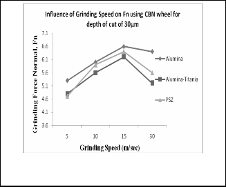
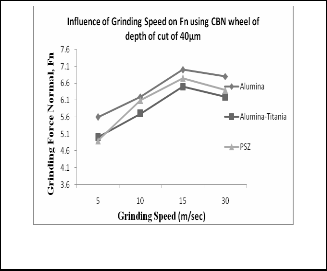
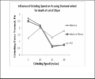
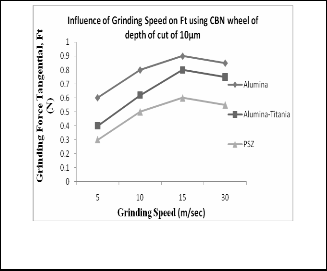
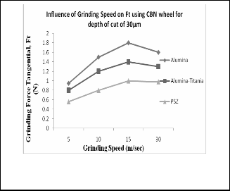
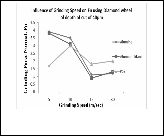
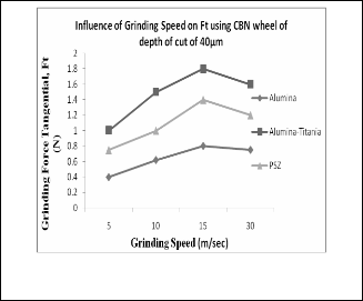
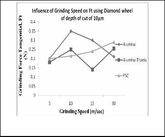
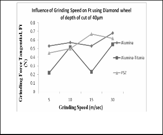
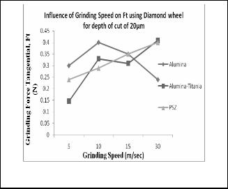
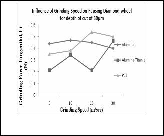
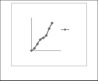
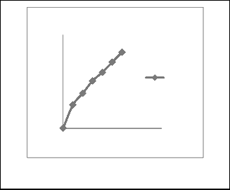
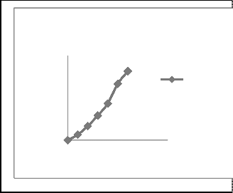
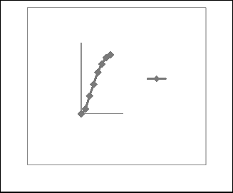
It has been noticed that, during the grinding of ceramic coa t- ings, grinding forces were found to be varying considerably with increasing grinding speed. Also, it is observed that, with CBN wheels grinding force components (Ft and Fn) were found to be higher when compared to diamond grinding wheel as shown in figures1, 2, 3, 4, 5, 6, 7, 8, 9, 10, 11, 12, 30, 31,
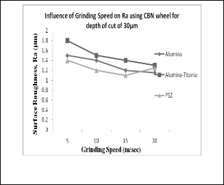
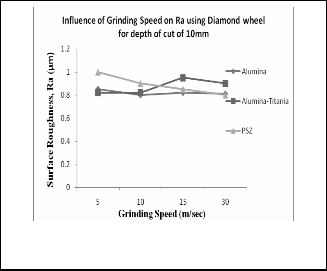
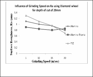
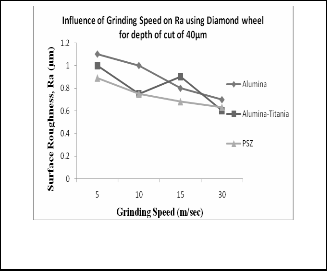
32 and 33. Besides, it is noticed that, the increase in the depth of grinding, generally improved the surface finish. During trials on grinding of ceramic coatings, grinding velocity, a range of 10 – 15 m/sec and depth of grinding 30µm were a s- sessed to be more critical. It is also observed grinding of Al u- mina-Titania (AT) and Partially stabilized zirconia (PSZ) c e- ramic coatings with diamond wheel gave better surface finish.
3.2 Results of Lapping
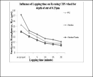
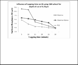
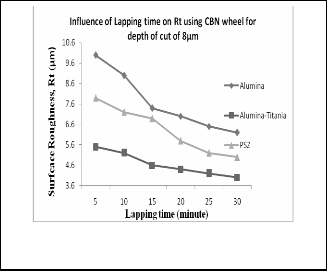
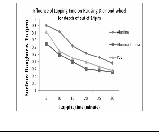
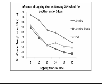
It is concluded that, surface finish of lapped ceramic coa t- ings, improved with lapping time and remains constant after
15 minutes of lapping time in case of AT and PSZ, whereas in
case of Alumina (A), it attains saturation after 20 minutes of lapping time. It is also seen among the coatings that, AT could be lapped better than the other two.
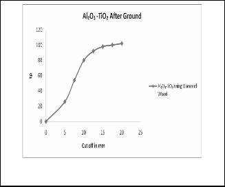
Bearing area characteristics of sprayed and ceramic coa t- ings with diamond wheels are shown in figures 36, 37, 38, 39,
40, 41, 42, 43, 44 and 45. It is observed there is no much varia-
tion in the bearing area characteristics of coated ceramic su r- faces subjected to diamond wheel grinding, but AT exhibits faster tendency to attain cent percent tp area. With CBN grind- ing, rapid improvement in bearing area characteristics of Alumina is observed due to improved grinding of brittle ma- terials (like Alumina). This is due to grinding forces ass ociated with CBN grinding wheels, CBN grains, cuts the ceramics rel- atively cooler (CBN is thermally more conductive) compared to diamond wheel. It is also seen that, diamond wheel is more sensitive to grinding condition and with CBN wheel it is poss- ible to go for higher depth of grinding , because of better thermal properties of CBN.
3.3 Results of Oil Retainabilty Test
Ceramics find wider applications from bearings to critical components of I.C.Engines. Some of the applications require for porosity control to enhance the strength and also to pro- vide adequate film and damping qualities. For evaluating oil retention capability and to find out the surface quality during precision machining, oil machining test have been carried out. It is seen that, as sprayed ceramic surface could not retain more oil on the surface (because of its layer surface porosity) and hence the oil film thickness was found to be less, but thickness of oil film on ground and lapped surface was larger
IJSER © 2012
http :// www.ijser.org
Inte rnatio nal Jo urnal o f Sc ie ntific & Eng inee ring Re se arc h, Vo lume 3, Issue 1, January -2012 3
ISS N 2229-5518

compared with the as sprayed ceramic surface. This may be due to the closure of pores in surface grinding. It is seen that, closure of pores and surface asperities take place on the su r- faces of AT and PSZ coating than with Alumina coatings. Lapping further improved surface finish of ceramic coa tings by reducing porosity and oil film thickness on the lapped su r- face was correspondingly higher. The oil retainability of the different coated plates after machining to 10μm depth of cut on the basis of three hours observation is shown table 3.
Table 3. Results of oil speadability in diameter
Condition Alumina Alumina- Titania
Par tial stabi- lized zir conia
As
sprayed
2 times 2 times 2 times
Grinding 3 times 1.25times 2.5times
Lapping 3.5 times 1 time 2.75 times
Fig. 3. Normal f orce v/s grinding speed using CBN w heel and depth of cut 30μm.
The occurre nce o f e arly be aring are a improve me nt fo r AT and PS Z co at- ing by g rinding and lapping c an be v isualize d in the marg inal diffe re nce in film thic kness.
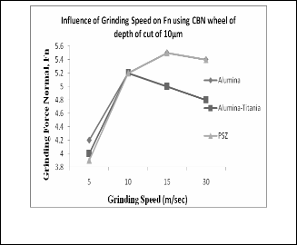
Fig. 4. Nor mal f orce v/s grinding speed using CBN w heel and
depth of cut 40μm.
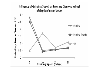
Fig.1. Normal f orce v/s grinding speed using CBN w heel and
depth of cut 10μm.
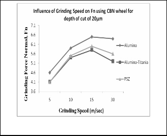
Fig. 5. Nor mal f orce v/s grinding speed using Diamond w heel and depth of cut 10μm
Fig. 2. Normal f orce v/s grinding speed using CBN w heel and
depth of cut 20μm.
IJSER © 2012
http :// www.ijser.org
Inte rnatio nal Jo urnal o f Sc ie ntific & Eng inee ring Re se arc h, Vo lume 3, Issue 1, January -2012 4
ISS N 2229-5518

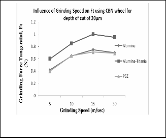
Fig. 6. Nor mal f orce v/s grinding speed using Diamond w heel and depth of cut 20μm.
Fig. 9. Tangentia l f orce v/s grinding speed using CBN w heel and
depth of cut 10μm.
Fig. 7. Nor mal f orce v/s grinding speed using Diamond w heel and depth of cut 30μm.
Fig. 10. Tangential f orce v/s grinding speed using CBN w heel
and depth of cut 20μm.
Fig. 8. Nor mal f orce v/s grinding s peed using Diamond w heel and depth of cut 40μm
Fig. 11. Tangential f orce v/s grinding speed using CBN w heel and depth of cut 30μm.
IJSER © 2012
http :// www.ijser.org
Inte rnatio nal Jo urnal o f Sc ie ntific & Eng inee ring Re se arc h, Vo lume 3, Issue 1, January -2012 5
ISS N 2229-5518
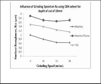
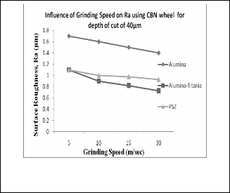
Fig. 12. Tangential f orce v/s grinding s peed using CBN w heel and depth of cut 40μm.
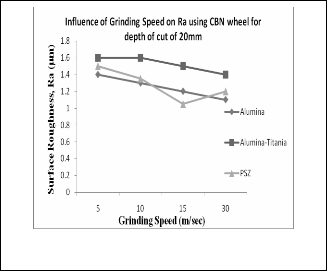
Fig. 15. Surf ace roughness (Ra) v/s grinding speed using CBN
w heel and depth of cut 30μm.
Fig. 13. Surf ace roughness (Ra) v/s grinding speed using CBN
w heel and depth of cut 10μm.
Fig. 16. Surf ace roughness (Ra) v/s grinding speed using CBN
w heel and depth of cut 40μm.
Fig. 14. Surf ace roughness (Ra) v/s grinding speed using CBN
w heel and depth of cut 10μm.
Fig. 17. Surf ace roughness (Ra) v/s grinding speed using Di-
amond w heel and depth of cut 10μm.
IJSER © 2012
http :// www.ijser.org
Inte rnatio nal Jo urnal o f Sc ie ntific & Eng inee ring Re se arc h, Vo lume 3, Issue 1, January -2012 6
ISS N 2229-5518
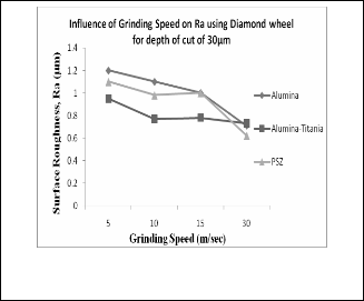
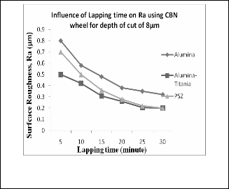
Fig. 18. Surf ace roughness (Ra) v/s grinding speed using Di- amond w heel and depth of cut 20μm.
Fig. 21. Surface roughness (Ra) v/s lapping time using CBN
w heel and depth of cut 0.25μm.
Fig. 19. Surf ace roughness (Ra) v/s grinding speed using Di- amond w heel and depth of cut 30μm.
Fig. 22. Surface roughness (Ra) v/s lapping time using CBN

w heel and depth of cut 8μm.
Fig. 20. Surf ace roughness (Ra) v/s grinding speed using Di- amond w heel and depth of cut 40μm.
Fig. 23. Surf ace roughness (Ra) v/s lapping time using CBN
w heel and depth of cut 14μm.
IJSER © 2012
http :// www.ijser.org
Inte rnatio nal Jo urnal o f Sc ie ntific & Eng inee ring Re se arc h, Vo lume 3, Issue 1, January -2012 7
ISS N 2229-5518
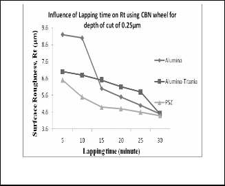
Fig. 27. Surf ace roughness (Rt) v/s lapping time using CBN
w heel and depth of cut 0.25μm.
Fig. 24. Surf ace roughness(Ra) v/s lapping time using Diamond
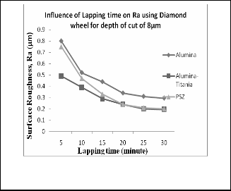
w heel and depth of cut 0.25μm.
Fig. 25. Surf ace roughness(Ra) v/s lapping time using Diamond w heel and depth of cut 8μm.
Fig. 28. Surf ace roughness (Rt) v/s lapping time using CBN
w heel and depth of cut 8 μm.
Fig. 26. Surf ace roughness(Ra) v/s lapping time using Diamond w heel and depth of cut 14μm.
Fig. 29. Surf ace roughness (Rt) v/s lapping time using CBN
w heel and depth of cut 14 μm.
IJSER © 2012
http :// www.ijser.org
Inte rnatio nal Jo urnal o f Sc ie ntific & Eng inee ring Re se arc h, Vo lume 3, Issue 1, January -2012 8
ISS N 2229-5518
Fig. 30. Tangential f orce v/s grinding speed using Diamond w heel and depth of cut 10μm.
Fig. 33. Tangential f orce v/s grinding speed using Diamond w heel and depth of cut 40μm.
120
100
80
60
40
20
0
Al₂O₃ Sprayed
0 100
Cut off in mm
Al₂O₃
Spray…
Fig. 31. Tangential f orce v/s grinding speed using Diamond w heel and depth of cut 20μm.
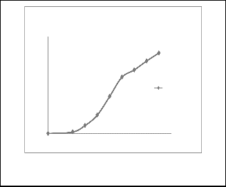
Fig. 34. % Bearing area(tp) v/s cutoff for as sprayed Alumina.
120
100
80
60
40
20
0
0 100
Cut off in mm
Al₂O₃-TiO₂
Sprayed
Fig. 32. Tangential f orce v/s grinding speed using Diamond
w heel and depth of cut 30μm.
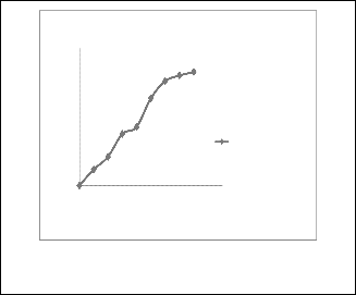
Fig. 35. % Bearing area(tp) v/s cutoff f or as sprayed Alumina- Titania (AT).
IJSER © 2012
http :// www.ijser.org
Inte rnatio nal Jo urnal o f Sc ie ntific & Eng inee ring Re se arc h, Vo lume 3, Issue 1, January -2012 9
ISS N 2229-5518
120
100
80
60
40
20
0
Al₂O₃ -TiO₂ Sprayed
Al₂O₃- TiO₂ after lapping
0 5 10
Cut off in mm
120
100
80
60
40
20
0
0 5 10
PSZ
after…
Fig. 36. % Bearing area (tp) v/s cutoff after lapping surf ace of
Alumina-Titania (AT).
Fig. 39. % Bearing areCau(tp)ovff/sincumtoffmafter lapping surf ace of
PSZ.
120
100
80
60
40
20
0
PSZ Sprayed
0 50 100
Cut off in mm
PSZ
Sprayed
Fig. 37. % Bearing area (tp) v/s cutoff for as sprayed PSZ.
Fig. 40. % Bearing area (tp) v/s cutoff , ground w ith diamond w heel f or Alumina-Titania (AT).
120
100
80
60
40
20
0
0
Al₂O₃ After lapping
C5ut off in m1m0 15
120
100
80
60
40
20
0
PSZ After Ground
0 5 10 15 20 25
Cut off in mm
PSZ using CBN Wheel
Fig. 38. % Bearing area (tp) v/s cutoff after lapping the surf ace of
(A).
Fig. 41 % Bearing area (tp) v/s cutoff , ground w ith CBN w heel f or PSZ.
IJSER © 2012
http :// www.ijser.org
Inte rnatio nal Jo urnal o f Sc ie ntific & Eng inee ring Re se arc h, Vo lume 3, Issue 1, January -2012 10
ISS N 2229-5518
120
100
80
60
40
20
0
PSZ After Ground
0 5 10 15 20 25
Cut off in mm
PSZ After wear USING DIAMOND
120
100
80
60
40
20
0
Al₂O₃ After Ground
Al₂O₃ using CBN wheel
Fig. 42. % Bearing area (tp) v/s cutoff , ground w ith diamond w heel f or PSZ.
0 2 4 6 8 10
Cut off in mm
Fig. 45 % Bearing area (tp) v/s cutoff, ground wit h CBN wheel for
Alumina (A)
120
100
80
60
40
20
0
Al₂O₃ -TiO₂ After Ground
0 10 20 30 40 50
Cut off in mm
Al₂O₃-TiO₂ using CBN wheel
4 CONCLUSION
Oxide ceramics such as Alumina (A), Alumina -Titania (AT) and Partial stablized zirconia (PSZ), Zirconia Toughened Alumina (ZTA) and Super-Z alloy have been widely used for many industrial applications by deposition of thick film of hard materials on a relatively softer substrate of the engineering components. Before deciding on particular type of coatings, it is essential to look into its characteristics which includes machinability for control of size and shape of end products. Hence it has become objective of the present work to characterise and machine for precision and to identify the optimal conditions for the development of oxide ceramic coatings. Based on the trials on grinding and lapping of
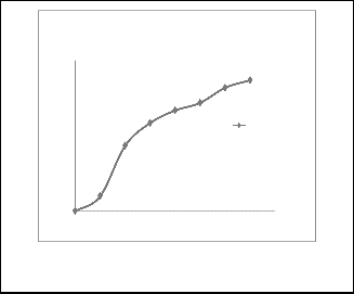
Fig. 43 % Bearing area (tp) v/s cutoff , ground w ith CBN w heel f or AT.
Al₂O₃ After Ground
120
100
80
Al₂O₃ with diamond wheel
60
40
20
0
0 2 4 6 8 10 12 14 16
Cut off in mm
Fig. 44 % Bearing area (tp) v/s cutoff, ground w ith Diamond w heel f or Alumina (A)
ceramic coatings the following conclusions are made.
1. With CBN grinding wheels, grinding force components (Ft and Fn) were found be higher when compared to diamond grinding wheel[20].
2. It is noticed that, increase in depth of grinding,
generally the surface finish is improved.
3. During grinding of ceramic coatings, grinding velocity range 10 – 15m/sec and depth of grinding
30µm were found to be more critical.
4. Grinding of AT and PSZ ceramic coatings generally give better surface finish with diamond wheel.
5. From the data obtained by lapping of ceramic
coatings, it is observed that, surface finish increases with lapping time and saturation of surface finish takes place after 15 minutes of lapping time in the three ceramic coating materials mentioned.
6. AT could be lapped better than the other two (
Ra=0.25 µm and Rt= 4.2µm).
7. Surface texture details show that, AT exhibits faster tendency to attain cent percentage tp area (bearing area characteristic).
IJSER © 2012
http :// www.ijser.org
Inte rnatio nal Jo urnal o f Sc ie ntific & Eng inee ring Re se arc h, Vo lume 3, Issue 1, January -2012 11
ISS N 2229-5518
8. With CBN wheels, it is possible to go for higher depth of grinding than using Diamond grinding wheel because of better thermal properties of CBN wheels.
9. The oil retainability test reveals the thickness of oil
film on ground and lapped surfaces were larger
compared with as sprayed ceramic surfaces, which is due to closure of pores and surface irregulariti es taking place on machined surfaces. Which ishelpful from the point of view of oil film lubrication between parts having relative motion.
The above work has taken as product and development of
ceramic coated s urfaces are having immens e value for indus trial applications .
REFERENCES
[1] ] Erry Yulian T. Adesta, Muhammad Riza, Muataz Hazza,De lv is Ag usman, Rose han Too l We ar and S urface Finish Inve stig atio n in Hig h S pee d Turning Using Ce rme t Inse rt by Apply ing Neg ative Rake Ang le s Euro pe an Jo urnal o f Sc ie ntific Re se arc h,Vo l.38 (2), 2009, pp.180-188.
[2] Thamizhmanii S ., Kamarudin K., Rahim E.A., S aparudi n A., Hassan S., 2007. Too l We ar andS urfac e Ro ug hne ss inn Turning AIS I 8620 using Co ate d Ce ramic Too l, Procee dings o f The Wo rld Co ng re ss o n Eng inee ring Vo l. II WCE, 2007, Lo ndo n, UK.
[3] Se nthilkumar A., Rajadurai A., and So rnakumar A., 2003.
Mac hinability o f harde ne d stee l using alumina base d ce ramic c utting too ls, Inte rnatio nal Jo urnal o Re frac to ry Me tals and HardMate rials,
21 pp. 109-117.
[4] Ms. Shruti Me hta, Mr. Av adhoo t Rajurkar, Mr. Jig ne sh Chauhan, A Rev ie w o n Curre nt Re se arc h Tre nds in Die -S inking Elec tric al Disc harge Mac hining o f Co nduc tive Ce ramic s, Inte rnatio nal Jo urnal o f Rece nt Tre nds in Eng inee ring , Vo l. 1(5), 2009, pp.100 -104.
[5] Yaho ng Liang and So urin P Dutta, “Appl ic atio n tre nd in adv anc e d ce ramic tec hno logy ”, Technova tion 21(2001), pp. 61-65.
[6] R. A. Mahdav inejad, A. Mahdav ine jad, “ED mac hining o f WC -Co ”,
Journa l of ma teria ls processing technology, 162-163, 2005, pp. 637 -643.
[7] M. Wakuda, Y. Yamauc hi and S . Kanzaki “Effec t o f wo rk piece pro pe rties o n mac hinability in abrasiv e je t mac hining o f ce ramic mate rials”, Public atio n: Prec isio n Eng inee ring , Vo lume 26 (2), 2002, pp. 193-198.
[8] H. Hoche ng, K.R. Chang , Mate rial Re mov al Analysis in Abrasive Wate r Je t c utting o f Ce ramic Plates, Jo urnal o f Mate rial Processing Tec hno logy, Elsev ie r, Vol. 40, No . 5, 1994, pp.287 -304.
[9] Ko nig W., Po pp M., Prec isio n Mac hining o f Adv ance d Ce ramics, Ce ramic Bulle tin, Vo l.68 ( 3), 1989, pp.550 -553.
[10] Dr.J.Fazlur Rahman and Mo hamme d Yunus, ―Be ne fits o f TBC Co ating s o n Eng ine applic atio ns‖, Inte rnatio nal co nfe re nc e, INCAM
2009 at Kalsaling am Unive rsity , Tamil Nadu, India, Marc h 2009.
[11] Dr.J.Fazlur Rahman and Mo hamme d Yunus, Mec hanic al and Tribo log ic al c harac te ristics o f Tung ste n Carbide Co balt HVOF co atings, Inte rnatio nal co nfe re nce he ld at Anjuman co lleg e o f Eng inee ring, Bhatkal Oc to be r 2008.
[12] Mo hamme d y unus, Dr.J. Fazlur rahman, Opti mizatio n o f usage parame te rs o f ce ramic co ating s in hig h te mpe rature applic atio ns
using Tag uc hi de sig n, Int. J. o f Eng ine e ring scie nce and Tec
Eng inee ring Sc ie nce and Tec hno logy, Vo l.3(8), 2011, pp.193 - 198.
[13] Mo hamme d y unus, Dr.J. Fazlur rahman, An investig atio n to wards c harac te rizatio n o f the rmally spraye d industrial co ating s , Int. J. o f Adv ance d Eng inee ring Scie nc es and Tec hno log ie s Vol.10( 2), 2011, pp.6364 – 6371.
[14] Mo hamme d y unus, Dr.J. Fazlur rahman, Optimizatio n o f proce ss parame te rs o f we ar and hardne ss c harac te rizatio n o f industrial ce ramic coating s using Tag uc hi desig n appro ac h , Int. J. o f Adv ance d Eng inee ring Sc ie nces and Techno logies, Vo l.9(2), 2011, pp.193 - 198.
[15] S. Go wri, K. Naray ana, Prec isio n Grinding o f S pray e d Ce ramic co atings, 7th Annual Co nfe re nce , ASPE, USA, oc tobe r 1992.
[16] S. Go wri, K. Naray ana, S tudy o n Flat Lapping Charac te ristics o f Plasma spray e d Ce ramic Co atings, Inte rnatio nal Co nfe re nce o n surfac e Mo dific atio n Tec hno log ies, Nagsaka, Japan, oc to be r 1993.
[17] Cave ney , R.J., The il N.W., Grinding Alumina with Dio amo nd
Abrasiv e, NBS special public atio nb,1972, pp. 99.
[18] Che n. C., S aki.S ., InasakiI, Lappi ng adv ance d ce ramics, Jo urnal o f
Mate rials and Manufac turing processes, vo l 6(2), pp.211 -226.
[19] Dav is. C.E., A study o f the influe nce o f flat Lapping with Diamo nd mic ro abrasiv ray ing , Diamo nd Info rmatio n Se rie s 1.32, De bee rsIndustrial diamo nd div iio nU.K.
[20] Ho n. K.K., Charac te ristics o f fo rce patte rn in CBN g rinding ,1983, 24 th IMTDR co nfre nve pp.277 -283.
[21] Krishnamurhy R, annac halam L.M.,Go kulRatnam. C.V ., Grinding Transfo rmatio n o f to ug hne d Y-ZTP ce ramic s, Annals o f CIRP, Vo l40(1),1991, pp.331 -337.
[22] Marshe ll, S haw M.C., Fo rces in Dry S urface Grinding , ASME, pp. 51. [23] Malkim S ., Curre nt Tre nd in CBN Tec hno logy, Annals o f CIRP vo l
34, 1985, Pp. 557-563.
IJSER © 2012
http :// www.ijser.org