Engineering and Management, India, PH-9903967916. E-mail: desubhas@gmail.com
International Journal of Scientific & Engineering Research, Volume 3, Issue 11, November-2012 1
ISSN 2229-5518
Papers for International Journal of Scientific & Engineering Research on Railway Safety
Mr.Kaushik Banerjee, Mr.Subhas De, Mr. Rahul Sourav Singh
—————————— ——————————
OST accidents are caused when the pilot can’t see the signal- it happens when there is fog. Another chance of missing the signal is somehow the signal is
not lit or driver falls ill and cannot operate the system.
One of the proposed ways is to apply external magnetic force to pull the valve of the vacuum brake. This can be achieved by placing an electromagnetic bar along with the track just before the signal. As soon as the red signal is activated, simultaneously a strong magnetic field induced in the bar such that in case the train does not come to halt and passes the signal the high magnetic field pulls off the brake valve. The brake pipe hanging between the two adjoining bogies or engine and boogie must be fitted with a valve at the joint. There must be a stretch of induced magnet. Hence as it pulls off the valve the pipe's joint breaks and thus train comes to halt after a while. The brake pipes hanging between two compartments are fitted with a valve which is fixed firmly, but they are made up of magnetic material. Due to magnetic nature the valve gets pulled off due to high induced magnetic field.
Another method that can be applied is that signals be
————————————————
Kaushik Banerjee is currently Professor in Institute of Engineering and
Management, India, PH-09830203495.E-mail: kaushik.saltlake@gmail.com
Subhas De is currently pursuing masters degree program in Institute of
Engineering and Management, India, PH-9903967916. E-mail: desubhas@gmail.com
Rahul Sourav Singh is currently pursuing masters degree program in
Institute of Engineering and Management, India, PH-09681090300. E-mail: rahul.sourav.singh.85@gmail.com
fitted with a wave emitter which emits a particular frequency
wave which is accepted by the engine with which it matches. Every engine has a particular range of frequency and when a signal goes red it emits the frequency. The frequency is captured by the sensor fitted in the engine. When the frequency matches a message is sent to pilot and the guard by some physical activity like audio signal or light signal inside their cabins, on seeing that even if due to fog the driver misses to see the signal he can apply break by seeing it. We can make the braking system more reliable by applying Real time circuitry-if the pilot or guard doesn’t applies brake within a given time period of sensor sensing the signal meant for that train, automatically brake is applied.
The momentum of a moving body increases with the weight and speed of that body, this concept is important in the design of brakes. In the olden days brakes were generally of the hand lever type. They are substituted by more improved and safer brakes nowadays with the advancement of technology.
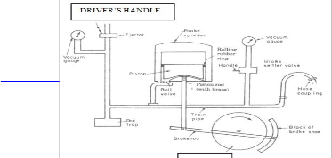
Vacuum brakes (Figure - 1) are mainly employed as railway brakes. The basic principle on which its operation is based, is the necessary force required for stopping the wheels.
IJSER © 2012 http://www.ijser.or
International Journal of Scientific & Engineering Research, Volume 3, Issue 11, November-2012 2
ISSN 2229-5518
admits the air into the train pipe thus applying brake
throughout the train. Two more important points to be noted are:
(i) Train pipe is connected at the junction of two coaches by using hose couplings.
(ii) Piston rod is made airtight by passing through a packing called gland packing ring.
This force is derived by the expansion of air
At atmospheric pressure against partial vacuum in a cylinder and the motion of piston thus obtained is transmitted to brake shoe. Let us now discuss the working of vacuum brake, when used as a railway brake. Initially (i.e. before starting the train) the driver moves driver handle in running position.
As a result, air is removed with the help of ejector from all the brake cylinders installed throughout the length of train. The air is removed both from the top and bottom side of the piston of cylinders, using ball valve and via train pipe till necessary vacuum, as indicated by the vacuum gauge, is obtained.
Now, when the train is moving and brakes are required to be applied the driver moves the driver handle to the necessary position. This makes the air at atmosphere pressure to enter into the train pipe through ejector. The air thus admitted is made to enter at the bottom side of the piston of the brake cylinders by the ball valve. The air is prevented from leaking to the top side of piston (through the clearance between piston and cylinder walls) by using rolling rubber rings. The rolling rubber rings make the piston airtight. Due to difference in pressure on the top side (at partial vacuum) and bottom side of piston (having air at atmospheric pressure) the piston moves up. As clear from the diagram this upward movement of the piston is transmitted to the brake shoes via connecting rod and brake rod. The brake shoes thus make contact with the moving wheels and the frictional force between the brake shoes and wheels stops the wheels and train comes to rest. Now, to release the brake, the driver handle is again returned to the running position which makes the air to be removed from the cylinders via train pipe and ejector.
It is important to note that the guard can also apply brakes by moving the handle of the brake settler valve. This
We use a strong magnetic bar (Figure – 2) with the rail track. It will be activated after deadline distance from signal post is crossed by the train. It will attract the vacuum break junction link between the two bogies. The vacuum hose coupling junction will be cut by the strong magnetic field from the track. After disconnecting the junction the train will be automatically retarded after certain distance. Thus we can prevent the huge accident.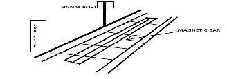
Figure – 2: Railway Track with magnetic Bar
Below Figure – 3 shows the condition before applying the magnetic field which is along the railway track. We are considering two bogies in the figure. But the mechanism is same throughout the all bogies.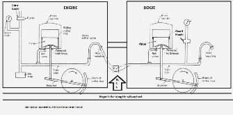
Figure – 3
In this figure the train is in running mode. The hose coupling is joined between two bogies. When we apply
IJSER © 2012 http://www.ijser.org
International Journal of Scientific & Engineering Research, Volume 3, Issue 11, November-2012 3
ISSN 2229-5518
strong magnetic field of attraction then the hose coupling will
be disconnected and the air goes to the lower part of the piston with ball valve (Figure -3).
As the pressure will increase to atmospheric pressure against the vacuum, the piston will go upwards. So it will pull the piston rod upward. The adjacent break rod will pull the break shoe. The frictional force will stop the train wheel after certain distance. The distance depends on the frictional force which is applied by the break shoe on the wheel. After applying the Magnetic field of attraction is shown in (Figure –
4).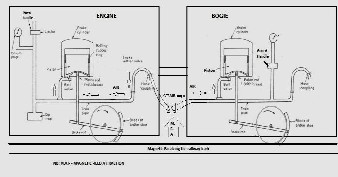
Figure - 4
In (Figure – 4) the air enters through the broken hose coupling junction is directed by arrow.
We know that Red, Green and Yellow light have specific wave length. Red Wave length (~620–740 nm) and frequency(
~480–400 THz)[1], Green (Wavelength 520–570 nm) and Frequency (~575–525 THz)[2], Yellow(Wavelength 570–590 nm Frequency 525–505 THz)[3].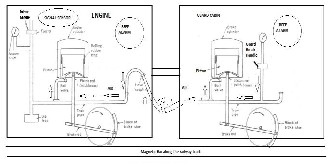
Every signal post is emitting this light with proper wave length and frequency. But now we are using extra emitting frequency wave to recognize the oncoming engine.
Figure – 5
Every engine has a receiver to receive the oncoming signal frequency and blow the wake up ring in the driver cabin and replicate the wake up ring in the guard cabin. So that the sleeping or sick driver can wake up and after deadline. The guard can also press the break (Figure – 5).
In Figure – 5, there is a signal sensor in the engine bogie. It will receive the red signal frequency and blow the alarm beeper inside the cabin and guard room. Then guard and driver both can press the break.
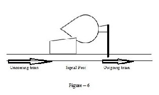
We are using one signal generator and one power supply.
This transmitter will be operated automatically in synchronization with the light signal. Whenever the signal turns red, the transmitter will also be turned on [Figure – 6].
The transmitted wave will reach the oncoming train which will receive the same using a receiver. The receiver in turn will set off an alarm sound and flashing light inside the driver’s cabin and optionally in the guard’s cabin.
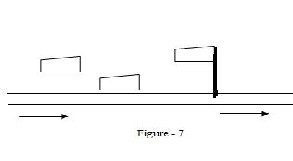
The braking distance of a train is to be considered. According to collected information, it is about 1.2KM. So, it is sufficient if the signal reaches the intended train when it is within 2 KM distance from the post. Any train beyond that distance may not be the intended one. Still if it is, then it will receive the signal when it comes within 2KM [Figure – 7].
IJSER © 2012 http://www.ijser.org
International Journal of Scientific & Engineering Research, Volume 3, Issue 11, November-2012 4
ISSN 2229-5518
Directive antennae are used to receive the signal from the post. This antenna is attached in front of the oncoming train at a good height from the ground. So that no other obstacle can disturb the receiving of the signal. We are using directive antenna because there may be two side by side posts of two side by side rail lines.
The electric field strength at a specific point can be determined from the power delivered to the transmitting antenna, its geometry and radiation resistance. Consider the case of a center-fed half-wave dipole antenna in free space (L=λ/2). It is constructed from thin conductors; the current distribution is essentially sinusoidal. After calculating the signal strength that will be at a particular point after which the signal has to be sighted for safety reasons, we can fix a threshold signal power equal to the signal strength calculated. Circuit is designed such that when the signal strength received by the receiver at the pilot's end of the oncoming train has crossed the threshold signal power then the signal alerts system will be activated.
Every track will have an assigned frequency. The posts on that track will transmit waves of that particular frequency. Every signal post on any particular track will be sending particular frequency signal and every oncoming train receives that signal. If it is red then there will be a alarm bell, otherwise it will pass the signal post. Again it will enter the region of next signal post frequency region. The previous signal post is now converted to the red and it emits a particular frequency signal. We are using frequency of a threshold level strength between two signal posts. So that ongoing train can understand the nearest post between two consecutive posts. Threshold strength of the signal will determine handoff. If the strength of the signal received is above the threshold level then the signal will be acknowledged.
We are concerning the breaking distance from post about
1.2 KM (maximum). So we are using the frequency of
100MHz range. It is more than sufficient for 1.2 KM distance. The power requirement for the system is very low. We can use solar power also.
Every signal post is emitting this light with proper wave
length and frequency. But now we are using extra emitting frequency wave to recognize the oncoming engine.
Every engine has a receiver to receive the oncoming signal frequency and blow the wake up ring in the driver cabin and replicate the wake up ring in the guard cabin. So that the sleeping or sick driver can wake up and after deadline. The guard can also press the break (Figure – 4).
In Figure – 4, there is a signal sensor (receiving antennae) in the driver’s cabin. It will receive the red signal frequency and blow the alarm beeper inside the cabin and guard cabin. Then guard and driver both can press the break.
We are using simple ways to avoid massive accidents. The accidents are unfortunate. But we can cut off the number of casualties with these ways.
[1] http://en.wikipedia.org/wiki/Red. [2] http://en.wikipedia.org/wiki/Green. [3] http://en.wikipedia.org/wiki/Yellow
IJSER © 2012 http://www.ijser.org