International Journal of Scientific & Engineering Research, Volume 5, Issue 2, February-2014 779
ISSN 2229-5518
PWM Boost Inverter at VAR mode in Rural Areas
Rafia Akhter
Abstract— The electrical infrastructure around the world is based on AC voltage, with a few exceptions, with a voltage of 120 Volt or 230 Volt in the distribution grid. But In Rural areas where the power supply is not available, there energy demand has to fulfill by renewable energy sources like solar/wind etc. Among these two sources solar energy is preferred as it is easily available in every part of the country in the world where as wind energy is restricted to the coastal area only. On average, most of today’s grid-tie PV inverters operate an average of 6-8 hours per day. In order to increase the utilization of grid-tie PV inverters, they can be operated in reactive power compensation mode when PV power is unavailable. While injecting reactive power into the grid can be easily realized by applying the appropriate phase shift between current reference and grid voltage, the task gets more complex when PV power is not available since the inverter needs to draw power from the grid, regulate the DC bus, and inject the desired level of reactive power. The paper presents development of a utility interface solar power Inverter that converts a solar energy directly to 220 V ac in Grid / DG power supply and enables inverter to absorb little active power from grid, regulate its DC bus voltage within limits, and inject the desired level of reactive power for a Solar lighting system used in rural areas.
Keywords- Solar; inverter; PWM; PV; Grid
1 Introduction
One type of renewable energy source is the photovoltaic (PV) cell, which converts sunlight to electrical current, without any form for mechanical or thermal interlink. PV cells are usually connected together to make PV modules, consisting of 72 PV cells, which generates a DC voltage between 23 Volt to 45 Volt and a typical maximum power of 160 Watt, depending on temperature and solar irradiation.. PV modules can therefore not be connected directly to the grid, but must be connected through an inverter. [1]
Rafia Akhter, BUET,Bangladesh
Assistant Professor, EEE East Delta University
rafia@eastdelta.edu.bd
Grid-tie inverters are at the heart of today’s renewable energy conversion systems. These inverters convert the energy harnessed from the various renewable energy sources, such as wind, sun, … into a grid quality AC power that can be fed into the utility grid. These inverters inject power into the grid as long as the renewable sources are active (i.e. if sun is out and wind is blowing). However, if the renewable sources are not available, such as during night hours in the case of PV systems, inverters will remain idle. This reduces the effective utilization of these inverters. One way to increase the effective utilization of these inverters is to operate them as VAR compensators to generate reactive power whenever the renewable sources are not available. As the number of grid-tied inverters increases, their usage as VAR compensators will help in grid voltage regulation and reduce the need of expensive capacity banks[2]. When active power is not available, the challenge is how to pre-charge the DC bus and keep it regulated within limits while injecting the desired level of reactive power into the grid. If the inverter is to merely operate in reactive power mode, it needs to compensate for its internal losses and keep its DC bus voltage within an acceptable range. Although a number of papers discuss the design of PV inverters and reference operation in VAR mode during night hours [3, 4, 5, 6], none of the aforementioned issues have been addressed or discussed. This paper will provide a novel control strategy that enables PV inverters to absorb little active power from the grid when the renewable source (e.g. sun) is not available to compensate for the inverters‟ internal losses, regulate the DC bus voltage to keep it within limits, and operate the inverters in VAR mode. This eventually extends the utilization of PV inverters beyond active power generation and helps improving grid stability and voltage regulation. Detailed design procedure is provided and will be validated by and will be validated by simulation and experimental results.
2 ANALYSIS OF VAR MODE
A grid-tie inverter (GTI) is a special type of inverter that converts direct current electricity into
IJSER © 2014 http://www.ijser.org
International Journal of Scientific & Engineering Research, Volume 5, Issue 2, February-2014 780
ISSN 2229-5518
alternating current electricity and feeds it into an existing electrical grid. Gridinteractive inverters typically cannot be used in standalone applications where utility power is not available. In grid tie mode, inverters usually operate in current mode to inject a desired current into the grid. The performance of the converter depends on the accuracy of the applied current control strategy. The phase-shift full- bridge converter is dopted in the first stage in this grid- connected inverter. The full-bridge DC-AC inverter is adopted in the second stage and the output current of the inverter is controlled to synchronize it with the utility grid. The output voltage of the PV array is increased by DC-DC circuit, supplying enough high bus bar voltage for the latter inverter circuit. This configuration of grid-connected PV system is shown in Fig.1.
Fig.1 Configuration of grid connected PV system
2.1 Normal operating mode
Fig. 2. shows the grid tie inverter which is preceded with a DC/DC stage, which regulates the DC bus voltage of the inverter. When the active power is not available, the DC/DC stage becomes idle. In normal operating mode the inverter convert the energy harnessed from the PV module into a grid quality AC power that can be fed into the utility grid. These inverters inject power into the grid as long as the renewable sources are active. During this mode of operation the capacitor acts as DC link. But when the renewable source is not available during night time the Grid tie Inverter becomes idle. To increase the utilization of the inverters during night it can be operated in VAR mode.[7]
Fig.2 Inverter in normal mode
2.2 VAR mode at night
Typically, grid-tie inverters are preceded with a
DC/DC stage that regulates the DC bus voltage of the
inverter; however when active power is not available, the
DC/DC stage becomes idle as shown in Fig. 3.
Fig.3 Inverter in VAR mode
However an appropriate control scheme can help the inverter operate in reactive power compensation mode even with the absence of active input power. Operating the inverter in VAR mode involves two steps,
1. Pre charging the DC bus capacitance
2. Regulating the DC bus voltage within limits while
regulating the injected reactive power
The inverter needs to draw some active power from the
grid in order to precharge the DC bus capacitor. In the
following sections, these steps will be discussed in greater detail.
3 INVERTER SWITCHED TO REACTIVE MODE
Normally when the active power is not available the inverter remains idle. Here the inverter utilization is improved by operating the inverter in VAR mode. In order to operate in VAR mode, the DC bus capacitor must be pre charged first. To do so, the inverter can be operated as a line rectifier by utilizing the inverter switches’ anti parallel diodes as shown in Fig. 4.
Fig.4 Anti parallel diodes across inverter switches acts as rectifier
3.1 PRECHARGING OF CAPACITOR
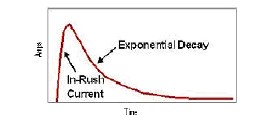
Peak inrush current as shown in Fig. 5. when flowing into a high voltage capacitor upon power up can stress the component, reducing its reliability. When a long life of the components and a high reliability of the high voltage system are needed, then a power-up method which reduces and limits the power-up stress is required.
IJSER © 2014 http://www.ijser.org
International Journal of Scientific & Engineering Research, Volume 5, Issue 2, February-2014 781
ISSN 2229-5518
Fig. 5 Inrush current
Since most PV inverters incorporate AC relays to connect
/disconnect from the AC grid, the same relays can be employed to pre charge the DC bus as shown in Fig. 6. In order to limit the current inrush and minimize the potential for a voltage overshoot across the DC bus, an inrush limiting circuit needs to be incorporated.
Fig. 6 Precharging the capacitor
• During normal operation (active power mode), the main
and pre-charge relays are switched together.
• In VAR mode, the main relay is closed first while the pre- charge relay is delayed.
• So the pre-charge resistor is connected in series with the
DC bus capacitor thus limiting the inrush current.
• Allowing proper charging of DC bus capacitor.
• Once the DC bus capacitor is fully charged, the precharge relay is closed to short the resistor and initiate the VAR compensation mode.
4 INVERTER DESCRIPTION
The typical single phase VSI uses the topology which has the characteristic that the average output voltage is always lower than the input dc voltage. Thus if an output voltage higher than the input one is needed, a boost dc-dc converter must be used between the dc source inverter. Depending on the power and voltage levels involved, this solution can result in high volume, weight, cost and reduced efficiency. The full bridge topology can, however, be used as a boost inverter that can generate an output ac voltage than the input dc voltage [8, 9]. But in case of boost inverter the average output voltage is always higher than the input dc voltage. In this paper, a technique of boost inverter is used which gives direct 220V ac conversion.
4.1 CIRCUIT DESCRIPTION
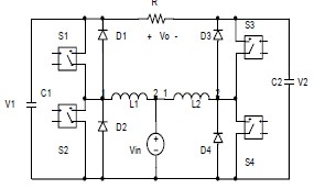
Fig.7 The DC-AC boost converter
Mode 1: When the switch S1 is closed and S2 is open as shown in fig.8a ,current iL1 rises quite linearly, diode D2 is reverse polarized, capacitor C1 supplies energy to the output stage, and voltage V1 decreases.
Mode 2: When switch S1 is open and S2 is closed as shown in fig.8b ,current iL1 flows through capacitor and the output stage. The current iL1 decreases while capacitor C1 is recharged.
5 SIMULATION AND EXPERIMENTAL RESULTS
The parameters of the circuit for fig. 8 are as follows: S1 – S5 : IRGBC40U (IGBT);
D1-D5 : MUR850 (diodes); C1-C2- C3 : 400 uF
L1 -L2-L3 : 10 mH Frequency, f=50Hz. R= 200 ohm
Vin = 12 Vdc
Vout = 220 Vac
IJSER © 2014 http://www.ijser.org
International Journal of Scientific & Engineering Research, Volume 5, Issue 2, February-2014 782
ISSN 2229-5518
Fig.8 The inverter output
6 CONCLUSION
This paper presented is to increase the utilization of PV inverters, as a key element in smart grids, beyond the active power generation during day time. The performance of the current controlled voltage source inverter is studied which gives direct 12Vdc conversion to 220 Vac . On average, most of today’s grid-tie PV inverters operate an average of 6-8 hours per day. So by using PWM boost inverter in VAR mode, the utilization of grid-tie PV inverters may increase and it will help the locality in rural areas.
REFERENCES
[1] Søren Bækhøj Kjær,” Design and Control of an Inverter for
Photovoltaic Applications”, 2012.
[2] A. Maknouninejad, M. Godoy Simoes, M. Zolot, “Single Phase and Three Phase P+Resonant Based Grid Connected Inverters with Reactive Power and Harmonic Compensation Capabilities”, IEEE Tr. IEMDC 09, 3-6 May 2009, pp. 385-391.
[3] A.O. Zue, A.Chandra, “Grid Connected Photovoltaic Interface with VAR Compensation and Active Filtering Functions”, PEDES 2006, pp 1-6.
[4] Kuo Yeong-Chau, Liang Tsorng-Juu; Chen Jiann-Fuh "A high efficiency single-phase three-wire photovoltaic energy conversion system" IEEE Trans.on Industrial Electronics, vol. 50, no 1, pp. 116-122, Feb. 2003.
[5] Huajun. Yu, Junmin. Pan, and An. Xiang, "A multi-function grid connected PV system with reactive power compensation for the grid", Solar Energy, vol. 79, no. 1, pp. 101-106, July. 2005.
[6] Nak-gueon Sung Jae-deuk Lee; Bong-tae Kim; Minwon Park; In- keun Yu "Novel concept of a PV power generation system adding the function of shunt active filter" in proc. 2002 Power Engineering Society Transmission and Distribution Conf, pp. 1658-63.
[7Ali Maknouninejad, Nasser Kutkut & Issa Batarseh ,“Analysis and
Control of PV Inverters Operating in VAR Mode at Night”
[8]Ramon, Ivo Barbi,” A boost dc-ac converter analysis ,design and
Experimentation “, IEEE Transactions on Power Electronics, vol. 14,pp.
134-141, January 1999
IJSER © 2014 http://www.ijser.org