The research paper published by IJSER journal is about PERFORMANCE IMPROVEMENT OF AN OIL FIRED FURNACE THROUGH OSCILLATING COMBUSTION TECHNOLOGY 1
ISSN 2229-5518
PERFORMANCE IMPROVEMENT OF AN OIL FIRED FURNACE THROUGH OSCILLATING COMBUSTION TECHNOLOGY
M.V. Aditya Nag
Department of Mechanical Engineering
Gokaraju Rangaraju Institute of Engineering Technology
Bachupally, Hyderabad-500090, India
E-mail address : nagaditya88@yahoo.com
Ramana Reddy Dareddy
Department of Mechanical Engineering
Gokaraju Rangaraju Institute of Engineering Technology
Bachupally, Hyderabad-500090, India
E-mail address: ramana4u.iitm@gmail.com
Abstract— Energy is one of the important crucial input factor in the thermal industries require new combustion concepts for effective utilization of the fuel with controlled emissions.Due to the depletion of fossil fuels at alarming rate and increasing of pollution levels from the various combustion processes such as I.C. Engines, boilers and furnaces, the need arises for the evolution of the new combustion techniques in contrast with the existing combustion techniques. The increased consumption rate and crude oil price leads to the usage of alternate fuels or newer technological development. Furnaces operating below optimum efficiency and emission levels can be improved by new technological approaches by retrofitting in new systems. Oscillating combustion is relatively a simple process. It is accomplished by introducing an oscillating valve on the path of the fuel line. The oscillations are introduced by the valve which operates at different amplitudes and oscillating frequency. The effect of these oscillations is increased heat transfer to the load which results in low fuel consumption, increased production rate and boosts furnace efficiency. Oscillating combustion methodology for overall improvement performance of an aluminium foundry furnace was taken up. Overall Equipment Effectiveness (OEE) of an oil fired furnace which is a metric for total productive maintenance initiative has been calculated. The results of these experiments led to significant savings in fuel consumption, enormous reduction in NOx emissions and highly cost effective which results in revenue savings.
Keywords: Oscillatory Combustion Technology, oil fired crucible furnace, fuel consumption, efficiency
I. INTRODUCTION
Manufacturers using natural gas fired industrial furnace must comply with increasingly stringent regulations on NOx emissions without compromising production quality. Oscillating combustion is a low-cost, patented, low-NOx, high efficiency technology that can be integrated in any combustion system and whose principle is based on a cyclic perturbation of gas line [1]. Stretcher, Eric et al (2001) have reported that in oscillating combustion, the flow of fuel is oscillated around the stoichiometric value. This action produces alternating fuel-rich and fuel-lean zones within the flame, which produces less NOx
than stoichiometric conditions [2]. As regard to energy conservation opportunities, the furnace efficiency can be improved by reducing the heat losses. The greatest contribution to the heat losses is the heat carried away by the flue gas leaving chimney. This can be controlled, by having a good check and control over the excess air supplied to the furnace [3]. A system utilizes oscillating combustion technology through introducing an oscillating valve on the flow of fuel to the burner to achieve improved operational performance of combustion process. An oscillating valve was designed and fabricated by this author and introduced on the path of fuel flow and tested at different operating conditions. The effect of the oscillations was to produce fuel-rich and fuel-lean zones in the flame. Fuel rich zones are more luminous and longer length with increased turbulence due to oscillations; produce low emissions and results in higher heat transfer rate [4]. The aim of developing the oscillating valve as one of the fuel efficient technologies for cost effective operations is introduced in fossil fuel fired furnaces such as aluminum melting furnaces and glass melting furnaces [8]. The tests have shown higher efficiency in terms of low fuel consumption with visibly low emissions.
II. MATERIALS AND METHOD USED FOR OPTIMIZATION
The test equipment comprises of a medium size oil fired crucible furnace, crucibles of different sizes, digital temperature indicator, a blower with motor, oscillatory valve with electromechanically circuits for controlling of the frequency, a U- shaped manometer to calculate the amount of air flow in the furnace as shown in figure 1 and 2. An oil filter is placed between the fuel container and the for controlling the furnace system and to the oscillatory value to filter any micro dust particles in the diesel reaching to the value and further to the burner nozzle to avoid and blockage during experimentation. Two Burettes is connected to the fuel tank which is placed at a height and also nearly the furnace setup using the three way cork for the measurement of the accurate amount fuel flow rate to the burner. A gun type burner is used in this experiment which has an adjustment in it to vary the
IJSER © 2012 http://www.ijser.org
The research paper published by IJSER journal is about PERFORMANCE IMPROVEMENT OF AN OIL FIRED FURNACE THROUGH OSCILLATING COMBUSTION TECHNOLOGY 2
ISSN 2229-5518
amount of fuel and air passing through it to the nozzle. A small furnace having the volume around 0.0829 m3 could accommodate a crucible in which the stock can be placed.
Aluminum stocks of varying mass were placed in the crucible and the crucible was placed in the furnace. An air box is connected to the blower. Digital temperature indicator with sensing probe was used to obtain the temperatures of the stocks. The electro-mechanical value or oscillating valve [] comprising two different CAMs at different amplitudes (100o
& 40o) is being introduced in the experimentation process for inducing the oscillations in the fuel ahead of the burner. Aluminum is used for the experimental investigations.
Different weight of stocks were placed in the furnace and subjected to different air fuel ratios and at different oscillating conditions. Relation between furnace efficiency, mass fuel consumption Melting Time with the changes in the mass of
the stock at different conditions of experimental set up (figure
1&2) such as furnace working without oscillatory combustion valve (Case 1); with oscillatory valve with 40o amplitude and
10Hz frequency (Case 2) and with oscillatory valve with 100o
amplitude and 10Hz frequency in being noted. Observations are being made using resultant data at different phases such as percentage changes in the furnace efficiency; melting time and mass fuel consumption with respect to the different weights of the stock.
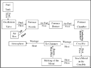
Figure 1. Schematic of furnace setup
III. RESULTS AND DISCUSSION
The Furnace embedded with an oscillating valve was operated at different air-fuel ratios varying from 14:1 to
17:1.According to the observations made by Aditya Nag et al.
[7] the maximum efficiency was found when the fuel is kept at
14:1 A/F ratio for the initial 30minutes and later changed to
17:1 A/F ratio. This is done for regulating the temperature in the furnace and also to minimize the fuel consumption in the furnace without varying the status of the furnace during the experimentation process. The results and discussions in this paper are based on 14:1-17:1 air-fuel ratio for different
performance characteristics between two different CAMs (at
20o & 80o amplitude). They are studied during the experimental process at different conditions by using the oscillatory valve .
A. Relation between Melting time and weight of the stock
According to the observations made from the Figure 2 and Table 1 which represents the relation between the melting time and weight of the stock .It is being noted that the melting time with respect to the weight if the stock in minimum using the
100o Amplitude CAM in the electromechanical valve (i.e., oscillatory valve).The melting time when compared to the initial state of the furnace have improved economically through the introduction of the oscillatory valve. This is because when the load heats up faster , the heat transfer from
flame to the load increase due to more luminous fuel-rich zone and increased turbulence created by the oscillations produced
by the valve. The decrease in melting time of the load is the result of higher rate of heat transfer due to the oscillating combustion which is economic.
TABLE I. MELTING TIME AT DIFFERENT CONDITIONS AND WEIGHT OF THE STOCK AT 14:1-17:1 AIR FUEL RATIO
Weight of the stock used for experimentation (kg) | Melting Time taken by Experiment Material at different conditions (min) |
Weight of the stock used for experimentation (kg) | Without Oscillations | Oscillatory Condition |
Weight of the stock used for experimentation (kg) | Without Oscillations | o 40 Amplitude CAM | o 100 Amplitude CAM |
5 | 54 | 47 | 40 |
10 | 57 | 52 | 44 |
15 | 61 | 56 | 48 |
20 | 66 | 61 | 52 |
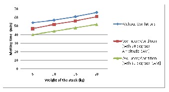
Figure 2. Relation between melting time and weight of the stock at different conditions at 14:1-17:1 air fuel ratio
B. Relation between mass fuel consumption and weight of the stock
The effect of the fuel consumption in the furnace in directly proportional to the weight of the stock but varies at different scenarios of the experimentation process. This is clearly observed from the table 2 and the figure 3. The fuel consumption was observed to be more for steady state combustion mode (Case 1) than that of the oscillating

Don’t write anything in this box. This is meant for the WAIRCO content.
IJSER © 2012 http://www.ijser.org
The research paper published by IJSER journal is about PERFORMANCE IMPROVEMENT OF AN OIL FIRED FURNACE THROUGH OSCILLATING COMBUSTION TECHNOLOGY 3
ISSN 2229-5518
combustion mode. It is also been noted that minimum fuel consumption of the oscillating made was found Case 3 than compared to that of Case 2. Though the fuel consumption is marginally more for higher loads but larger quantity of load was processed. During the oscillating combustion mode the fuel consumption was at its low for Case 3. There is a variation of 1kg of fuel less consumed during case 3 in comparison to the steady state combustion mode (case 1) for one of the operations. This can be stated as, within a reasonable short time the furnace all temperature becomes relatively uniform because time scale of the flame propagating is less and its velocity is faster due to more luminous flame from the fuel-rich zone of the flame [7].
TABLE II. MASS FUEL CONSUMPTION AT DIFFERENT CONDITIONS AND WEIGHT OF THE STOCK AT 14:1-17:1 AIR FUEL RATIO
Weight of the stock used for experimentation (kg) | Mass fuel Consumption at different conditions for melting of the stock (kg) |
Weight of the stock used for experimentation (kg) | Without Oscillations | Oscillatory Condition |
Weight of the stock used for experimentation (kg) | Without Oscillations | 40o Amplitude CAM | 100o Amplitude CAM |
5 | 3.66 | 3.20 | 2.59 |
10 | 3.87 | 3.48 | 2.75 |
15 | 4.16 | 3.59 | 2.99 |
20 | 4.48 | 3.98 | 3.13 |
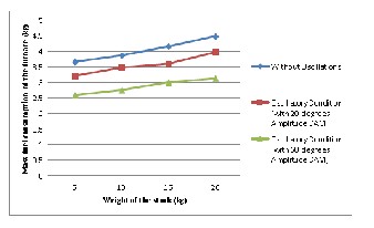
Figure 3. Relation between mass fuel consumption and weight of the stock at different conditions at 14:1-17:1 air fuel ratio
C. Relation between Furnace Efficiency and weight of the stock
From the Figure 4 and Table 3 it can be observed that the efficiency was found to be greater for 20kg of load at minimum oscillating frequency of the oscillating valve at 14:1-17:1 air- fuel ratio. The efficiency is found to be greater from steady state combustion mode to oscillating combustion mode. There is a huge increase inefficiency at lower frequency operation is due to the oscillations introduced by the oscillating valve oscillates the air-fuel ratio of 14:1-17:1 into above and below the stoichiometric ratio resulting in improved efficiency.
TABLE III. FURNACE EFFICIENCY AT DIFFERENT CONDITIONS AND WEIGHT OF THE STOCK AT 14:1-17:1 AIR FUEL RATIO
Weight of the stock used for experimentation (kg) | Efficiency of the furnace at different conditions (%) |
Weight of the stock used for experimentation (kg) | Without Oscillations | Oscillatory Condition |
Weight of the stock used for experimentation (kg) | Without Oscillations | 40o Amplitude CAM | 100o Amplitude CAM |
5 | 4.44 | 5.07 | 6.28 |
10 | 8.40 | 9.34 | 12.03 |
15 | 11.71 | 13.58 | 16.99 |
20 | 14.5 | 16.33 | 21.45 |
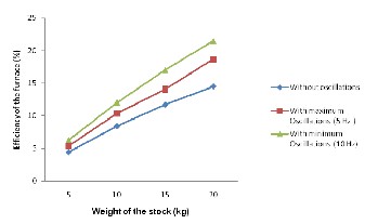
Figure 4. Relation between Furnace Efficiency and weight of the stock at different conditions at 14:1 -17:1 air fuel ratio
IV. CONCLUSION
The objective of this research work was a demonstration of the “Oscillatory Combustion Technology” on a diesel fired crucible furnace to melt aluminium for process operations. Oscillating combustion valve was installed in the testing furnace as a retrofit and carried our experiments to study the performance of the oil fired crucible furnace at different combustion modes through the study of different parameters (such as melting time, fuel consumption, heat transfer rate) and also through visual observations of various flames and emissions. The experimental results obtained using the test stand of oscillating valve in the furnace are very promising. The main conclusions that were drawn based on the data are:-
 There is an increase in furnace efficiency up to 6%.
 Fuel savings vary 7% to 39% in the oscillating combustion mode depending upon the condition.
 There is a huge increase in efficiencies for all loads during the oscillating combustion modes.
 The melting time observed with oscillating combustion operation is lower than the non oscillating
IJSER © 2012 http://www.ijser.org
The research paper published by IJSER journal is about PERFORMANCE IMPROVEMENT OF AN OIL FIRED FURNACE THROUGH OSCILLATING COMBUSTION TECHNOLOGY 4
ISSN 2229-5518
combustion mode. However there is a change in melting time within the oscillating combustion mode operation.
 The maximum efficiency, minimum fuel consumption and melting time of the stock are observed at oscillations at minimum frequency.
With all the above characteristics, the concept of Oscillating Combustion Technology is superior to the standard study state combustion technology currently being used in the heat transfer industries in terms of both energy efficient and consequential fuel cost savings as well as significantly helps reduce pollutant emissions.
ACKNOWLEDGMENT
The authors are grateful to the Management of GRRIET Engineering College, Nizampet, R.R. Dist. A.P & P.R.R.M.E.C., Shabad, R.R Dist., A.P., India, India for providing the facilities for the execution of this experimental analysis in the Thermal Engineering and Production Technology Laboratory at Department of Mechanical Engineering.
REFERENCES
[1] O. Delabroy, O. Louédin, R. Tsiava, G. Le Gouefflec, P.
Bruchet,"Oxycombustion for reheat furnaces:major benefits based on ALROLLTM ,A mature technology", AFRC / JFRC / IEA 2001 Joint International Combustion Symposium, Kauai, Hawaii,September 9 -
12,2001.pp. 1-23
[2] Stretcher, eric et al. oscillating combustion technology boosts furnace efficiency. Industrial heating. 2001. AFRC/JFRC/IEA 2001. Joint international combustion symposium. Air Liquide.
[3] Rajani K. and Varagami et al. Advanced control system for enhanced operation of oscillating combustion technology. Air Liquide ,TX, US,
2004
[4] John C. Wagner,NOX Emission Reduction by Oscillating Combustion, Gas Technology Institute,, GTI Project No. 61111, U.S. Department of energy,Contract No. DE-FC36-96EE41260, 2004.
[5] W. Tinks, Industrial furnaces (Vol.2), John Wiley and sons Inc. New
York, 1925.
[6] J. Govardhan, G.V.S. Rao, "Evaluation of thermal characteristics of oscillating combustion", International Journal of Engineering, Science and Technology,Vol. 2, No. 2, 2010, pp. 165-173.
[7] M.V.Aditya Nag, J.Govardhan, G.S.V.Rao, , “Experimental study of performance characteristics of a diesel fired furnace and optimization of its thermal energy”. Proceedings of International conference on fasninating advancements in mechanical engineering, 208 (F.A.M.E -
2008), Mepco Schlenk engineering college, Sivakasi, Tamilnadu, India, pp. 781-786.
[8] Kumar, R. N. and Culick, F. E. C. (1977) Role of Condensed Phase Details in the Oscillatory Combustion of Composite Propellants. Combustion Science and Technology, 15 (5). pp. 179-199
IJSER © 2012 http://www.ijser.org