Inte rnatio nal Jo urnal o f Sc ie ntific & Eng inee ring Re se arc h, Vo lume 3, Issue 2, February -2012 1
ISS N 2229-5518
Optimal Placement of Phasor Measurement Units for State Estimation using Artificial Intelligence Techniques
Ganga Reddy Tankasala, Sridhar Sanisetty, Varun Kumar Vala
Abs tract— This paper deals w ith a study carried out to determine the optimal locations of phasor measurement units (PMUs) f or a given pow er system. Pow er systems are rapidly becoming populated by PMUs as they provide valuable phasor inf ormation of voltages and currents f or protection, operation and control of pow er systems during normal and abnormal operation. This paper f ocuses on the use of PMU measurements in state estimators. The principle objective w as to investigate methods of determining optimal locations f or PMUs so that the entire pow er system is observable. The recently developed AI techniques, like Genetic Algorithm and artif icial bee colony techniques are applied to f ind out the optimal place ment of PMUs f or various systems. It is f ound that the entire system can be made observable by strategically placing PMUs at one-third of the system buses f or a given system.
Inde x Terms— Artif icial Bee colony (ABC), Artif icial Intelligence Techniques, Genetic Algorithm (GA), Phasor Measurements Unit (PMU), Pow er system, State estimation
—————————— ——————————
1 INTRODUCTION
ower systems operation mainly consists of data acquistion, monitoring and controlling of the system. of which the data acquisition and monitoring plays a very important role in
its secure operation. Before the advent of the Phasor measure- ment units (PMU)'s the data i.e, the analog and digital da- ta(statuses) of the circuit breakers from various substations are fed as input to the estimators present in the control center com- puter. Now with the development of GPS, these devices use a navigational satellite system to synchronize digital sa mpling at different substations. That summer the data was analysed using modem digital signal processing software.
State estimators of a power grid provide optimal estimates of bus voltage phasors based on the available measurements and knowledge about the network topology. These measurements are commonly provided by the remote terminal units (RTU) at the substations and include real/reactive power flows, power injections, and magnitudes of bus voltages and branch currents. More recently, synchronized phasor measurements have started to become available at selected substations in the system. One of the issues faced by the planning engineers is how to select the best locations to install new PMUs . Earlier work done by Phadke and his co-workers [1-2] introduces the use of PMUs for such applications. This work is later extended to the investiga- tion of optimal location of PMUs where each PMU is assumed to provide voltage and current phasors at its associated bus and all incident branches [3].
It is therefore possible to fully monitor the system by using rela- tively small number of PMUs much less than the number of buses in the system. This problem isformulated and solved by using a graph theoretic observability analysis and an optimiza- tion method based on Artificial bee colony [4]. Possible loss or failure of PMUs is not considered in that study.
werer
2 OPTIM AL PLACEM ENT O F PMUS
2.1 Problem Formulation
A numerical method based on Integer Programming is ex- plained here under to solve our problem. The formulation of problem is shown as below.
For an n-bus system, the PMU placement problem is formu- lated as follows:
Objective functio n (J) = Min (∑ W i * Xi) ∀ i ∈ Bus es (1)
Such that f(X) ≥ 1ˆ (2)
Where X is a binary decision variable vector, whose entries are defined as:
Xi = { 1 if a P MU is installe d at bus i ;
= { 0 othe rw ise (3)
Wi is the cost of the PMU installed at bus i.
f(X) is a vector function, whose entries are non -zero if the cor- responding bus voltage is solvable using the given measure ment set and zero otherwise.
1ˆ is a vector whose entries are all ones.
Inner product of the binary decision variable vector and the cost vector represents the total installation costs of the selected PMUs. Constraint functions ensure full network observability while minimizing the total installation cost of the PMUs.
IJSER © 2012
http :// www.ijser.org
Inte rnatio nal Jo urnal o f Sc ie ntific & Eng inee ring Re se arc h Vo lume 3, Issue 2 , Fe bruary -2012 2
ISSN 2229-5518
2.2 Con straints
The procedure for building the constraint equations de- scribed for three following possible cases is presented
1. No conventional measurement or zero injections
2. Flow measurements and
3. Flow measurements as well as injection measure- ments (they may be zero injections or measured in- jections).
Description of the procedure for each case is given using IEEE
14-bus system example for clarification.
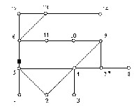
Fig 1.IEEE 14-bus system with conventional measurements
The numbers at each node represents the bus number. One can see the grid connections among all the buses.The con- straints, categorized in to three classes are discussed below in detail.
3 ILLUS TRATIONS
3.1 A system with no conventional measurements and/or measurements
In this case, the flow measurement and the zero injection are ignored. In order to form the constraint set, the binary connectivity matrix A, whose entries are defined below, has to be formed first:
Matrix A can be directly obtained from the bus admittance matrix by transforming its entries into binary form. Building the A matrix for the 14-bus system yields:
Ak,m = { 1 if a k=m or k a nd m a re co nne cted ;
= { 0 o therwise (4)
The A matrix for IEEE 14 bus system shown in fig (1) can be evaluated as
A = [0 0 0 0 0 0 0 0 1 0 0 0 1 1
0 0 0 0 0 1 0 0 0 0 0 1 1 1
0 0 0 0 0 1 0 0 0 0 0 1 1 0
0 0 0 0 0 1 0 0 0 1 1 0 0 0
0 0 0 0 0 0 0 0 1 1 1 0 0 0
0 0 0 1 0 0 1 0 1 1 0 0 0 1
0 0 0 0 0 0 1 1 0 0 0 0 0 0
0 0 0 1 0 0 1 1 1 0 0 0 0 0
0 0 0 0 1 1 0 0 0 0 1 1 1 0
1 1 0 1 1 1 0 0 0 0 0 0 0 0
0 1 1 1 1 0 1 0 1 0 0 0 0 0
0 1 1 1 0 0 0 0 0 0 0 0 0 0
1 1 1 1 1 0 0 0 0 0 0 0 0 0
1 1 0 0 1 0 0 0 0 0 0 0 0 0 ]
The constrants for this case can be formulated as
f(X) = A.X (5) The
fi = A (i, :) × X (i, 1) ∀ i ∈ Bus es of the g rid (6 )
f1 = ( X1 + X2 +X5 ) ≥ 1
f2 = (X1 + X2 + X3 +X4 + X5) ≥ 1 (7)
The operator “+” serves as the logical “OR” and the use of 1 in the right hand side of the inequality ensures that at least one of the variables appearing in the sum will be non -zero which means one of atleast 1, 2 and 5 numbered buses of eq (6) should be provided with aPMU to make bus1 observable.
Similarly the second constraint implies that one PMU should be installed at any of the buses 1,2,3,4 or 5 inorder to make bus
2 observable.
3.2 A system with atleast one flow measurement or zero injection bus
This case considers the situation where some flow mea- surements may be present. Existence of flow measurement will lead to the modification of the constraints for buses a c- cordingly. Modification follows the observation that having a flow measurement along a given branch allows the calculation of one of the terminal bus voltage phasors when the other one is known. Hence, the constraint equations associated with the terminal buses of the measured branch can be merged into a single constraint. In the case of the example system, the con- straints for buses 5 and 6 are merged in to a joint constraint as there is flow measurement in branch between 5 and 6.
f5 = (X1 + X2 + X4 + X5 + X6) ≥ 1 (8)
f6 = (X11 + X12 + X13 + X5 + X6) ≥ 1 (9)
f5-6 new = f5 + f6
= (X1 + X2 + X4 + X5 + X6 + X11 + X12 + X13) ≥ 1 (10)
Which implies that if either one of the voltage phasors at bus 5 or 6 is observable, the other one will be observable.
Remove the f5 and f6 from function f and them by new con- straint f5-6 new .
IJSER © 2012
http :// www.ijser.org
Inte rnatio nal Jo urnal o f Sc ie ntific & Eng inee ring Re se arc h Vo lume 3, Issue 2 , Fe bruary -2012 3
ISSN 2229-5518
3.3 A system with both injection measurements (some of which may be zero injection pseudo measurements) and flow measurements.
This case considers the most general situation where both injection and flow measurements may be present, but not enough to make the entire system observable. Injection mea- surements whether they are zero injections or not, are treated the same way. Consider again the same 14 -bus system shown in fig (1), where bus 7 is a zero injection bus. It is easy to see that if the phasor voltages at any three out of the four buses 4,
7, 8 and 9 are known, then the fourth one can be calculated
using the Kirchhoff‟s Current Law applied at bus 7 where the
net injected current is known.
One way to treat the injection buses is to modify the con- straints associated with theneighboring buses of th ese buses and form a set of non-linear constraints. This is accomplished as shown below. To treat the zero injection bus 7 in the IEEE
14-bus system, constraints associate with its neighboring buses
4, 8 and 9 will be modified as follows .
f4 = (X2 + X3 + X4 + X5 + X7 + X9 + f7.f8 .f9) ≥ 1 (11) f7 = (X4 + X7 + X8 + X9 + f4 .f8 .f9) ≥ 1 (12) f8 = (X7 + X8 + f4 .f7 .f9) ≥ 1 (13) f9 = (X4 + X7 + X9 + X10 +X14 + f4 .f7 .f8) ≥ 1 (14)
The operator „.‟ in the above equations serves as the logical “AND”Operation. The expressions for fi can be further simpli- fied by using the following properties of the Boolean logical AND (.) and OR (+) operators.
Given two sets A and B, where set A is a subset of set B,
then A + B = B and A⋅ B = A
By substituting f7, f8 and f9 in expression for f4, f4 can be writ-
ten as
f4 = (X2 + X3 + X4 + X5 + X7 + X9 + X8.X10 + X8.X14)
Applying similar simplification to other expressions, other constraints can be redefined as
f8 = (X4 + X7 + X8 + X9)
f9 = (X4 + X7 + X9 + X10 + X14 + X2.X8 + X3.X8 + X5.X8)
The constraints corresponding to all other buses will re- main the same as given in eq (2). The zero injection bus con- straint is eliminated as it is taken care of by its neighbors.
4 ARTIFICIAL B EE COLONY ALGOTITHM FOR OP TIM AL
PLACEM ENT O F PHAS OR M EAS UREMRNT UNITS
1. Generate n random solutions with in boundaries of the system
a. X = Boolean (rand (No of solutions, size of
solution))
2. Check that random solutions satisfy the inequality
constraints of buses i.e.
a. f(X) = (A.X ) ≥ 1ˆ
b. where A is binary impedance matrix , X is the solution.
3. Calculate the objective function and fitness of each s o- lution
4. Store the best fit as Xbest solution
5. A mutant solution is formed using a randomly s e- lected neighbour
a. If (rand > 0.5)
b. Xk mutant = Xk (i) OR Xj(i)
c. Else
d. Xk mutant = Xk (i) AND Xj(i)
e. Where j is the randomly selected neighbour and i is a
f. random parameter. OR and AND refers to
Boolean
g. Operators. Rand represents a random num- ber
h. between 0 and 1.
6. Check for constraints f(X) = (A.X ) ≥ 1ˆ . If the con- straints are satisfied proceed to step 7 , else move back to step 5.
7. Replace Xk mutant by Xk, if the mutant has higher fitness or lower cost of PMU.
8. Repeat the above procedure for all the solutions.
9. Onlooker bee phase (Simple ABC)
10. Probability of each solution is calculated as
a. Probability (i) =a*fitness (i)/max (fitness) +b b. Where {a+b =1}
11. The solution X is selected if its Probability is greater than a random number.
i. If (rand<probability (i))
ii. Solution is accepted for mutation . b. Else
c. Solution is discarded for mutation
12. Again the best Xbest is determined
13. Replace a X by random X if its trial counter exceeds threshold (Scout bee phase)
14. Repeat the above for max no of iterations
15. The Xbest and F (Xbest) are the best solution and Global minimum of the objective function.
5 PLACEM ENT O F PMUS FOR VARIOUS C AS ES
The integer bases artificial bee colony optimization method is tested on IEEE 14-bus, 30-bus, 57-bus and 118-bus systems. Detailed system information and simulation results are presented in the following sub-sections named 5.1, 5.2.5.3
and 5.4.
IJSER © 2012
http :// www.ijser.org
Inte rnatio nal Jo urnal o f Sc ie ntific & Eng inee ring Re se arc h Vo lume 3, Issue 2 , Fe bruary -2012 4
ISSN 2229-5518
5.1 IEEE 14 bu s system
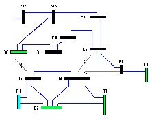
Fig 5.1 IEEE 14 bus system
The above mentioned system is considered for applying the ABC approach to find evaluate the optimal placement of PMU‟s in order to observe the total system.The results of the simulation are tabulated below.
Table 1. Simulation results of IEEE 14 bus system
Zero injec- tion buses | Number of branches | Location of PMUs | Total no. of PMUs |
None | 20 | 2,7,11,13 | 4 |
7 | 20 | 2,6,9 | 3 |
5.2 IEEE 30 bu s system
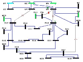
Fig 5.2 IEEE 30 bus system
The IEEE 30 bus system is simulated with and without con- sidering the zero injections and the results are tabulated in the below table.
Table2. Simulati on results of IEEE 30 bus system
5.3 IEEE 57 bu s system
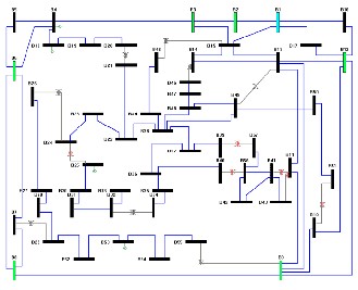
Fig 5.3 IEEE 57 bus system
Simulation results for above shown IEEE 57 -bus system with and without considering zero injections are tabulated in the table 5.3.
Table3. Simulati on results of IEEE 57 bus system
Zero injec- tion buses | Number of branches | Location of PMUs | Total no. of PMUs |
None | 78 | 1, 6, 13, 15, 18, 21, 22, 25, 27, 29, 32, 34, 38, 40, 41, 46, 51, 54, 57 | 19 |
4,7,11,21,22, 24,26,34,36, 37,39,40,45, 46, 48 | 78 | 1,6,9,15,20, 25,27,32,38, 47,50,53,56 | 13 |
5.4 IEEE 118 bu s system
Results of the IEEE 118 bus system simulated with and without considering the zero injections are tabulated below. The data of IEEE 118 bus system is presented in Table no 1 of the Appendice.
Table4. Simulati on results of IEEE 14 bus system
Zero injection buses | Number of branches | Location of PMUs | Total no. of PMUs |
IJSER © 2012
http :// www.ijser.org
Inte rnatio nal Jo urnal o f Sc ie ntific & Eng inee ring Re se arc h Vo lume 3, Issue 2 , Fe bruary -2012 5
ISSN 2229-5518
———— ——— ——— ——— ———
Each of the three authors trio holds Undergraduate grad uate degree from Elec- trical Engineering department of National Instit ute of Technology Warangal (NITW). They are currently working on “Artificial intelligent techniques for Modern engineering”.
Ganga reddy Tankasala , email id: gangareddy.ts@gmail.com ph: +91
Sridhar Sanisetty, email id: aries.sridhar@gmail.com ph: +919441894838
Varun kumar Vala, email id: varunkumar2205@gmail.com ph :+91
6 CONCLUSION
The ABC approach for solving a binary mode of op- timization gives the desired optimized results succesfully. The ABC approach gurantees a global or near global solution with a properly chosen colony parameters like maximum number of iterations, population size, onlooker bees, employed bees and threshold limit.
APP ENDICES
The standar d IEEE 57 Bus and IEEE 118 Bus systems data ar e pr esented in a separ ate document attached to avoid congestion of data in the paper. The same can be obtained fr om any IEEE w ebsite or other r eliable sour ces.
ACKNOWLEDGM ENT
We would like to convey our sincere regards to our mentor Dr. D.M.Vinod Kumar, Department of electrical Engi- neering, National Institute of Technology Warangal for his constant support in our endeavors.
REFERENCES
[1] A. G. Phadke, “Synchronized phasor measurements in power sys-
tems”, IEEE Computer Applications in Power, Vol. 6, Issue 2, pp. 10-
15, April 1993.
[2] A. G. Phadke, J. S. Tho rp, and K. J. Kari mi, “S tate Estimatio n with Phaso r Me asure me nts”, IEEE Transac tio ns o n Po we r Syste ms, Vol. 1, No. 1, pp. 233-241, Fe bruary 1986.
[3] T. L. Baldwin, L. Mili, M. B. Bo ise n, and R. Adapa, “Po we r Syste m
Obse rv ability With Minimal Phaso r Me asure me nt Place me nt”, IEEE
Transac tio ns o n Po we r Syste ms, Vol. 8, No . 2, pp. 707-715, May 1993.
[4] D.Karabog a, "An ide a Base d o n Ho ney Bee Swarm fo r Nume ric al Optimizatio n" , Technica l Repor-Tr06t, Erc iyes Unive rsity, Eng inee ring fac ulty, Co mpute r Eng inee ring De partme nt, Turkey, 2005.
[5] Be i Xu and A. Abur, “Obse rv ability Analy sis and Me asure me nt
Place me nt fo r Syste mswith PMUs”, Procee dings o f the IEEE PES Po we r Sy ste ms Co nfe re nce and Expo sitio n, Oc to be r 2004, New Yo rk, NY.
[6] Be i Xu, Y. J. Yoo n and A. Abur, “Optimal Plac e me nt and Utilizatio n
o f Phaso r Me asure me nts fo r S tate Estimatio n”, Po we r Syste m Co m- putatio n Co nfe re nce, Aug ust 2005, Liege , Be lg ium.
IJSER © 2012
http :// www.ijser.org