The research paper published by IJSER journal is about Optimal Corona Ring Selection for 230 kV Ceramic I-string Insulator using 3D Simulation 1
ISSN 2229-5518
A. Rahimnejad, M. Mirzaie
Abstract— Porcelain string insulators are extensively utilized in high voltage transmission lines. However, the electric field and potential distribution along an insulator string owing to the existence of metal conjunctions and resulting stray capacitances is not uni form and the units near to energized end fitting are more highly stressed. One practical way to improve the voltage distribution is corona ring installation at the energized side. Thus the investigation of electric field and potential distribution along insulators, in presence of va rious corona ring designs, is an effective method to choose the most appropriate one. In this paper 3-D software -based on Finite Element Method- is used to investigate the influences of three different corona ring types, which are more common in Iran 230 kV transmission line, conductor length and also insulator numbers on voltage distribution along 230 kV porcelain insulator string. Eventually, the simulation results will be discussed.
Index Terms— Corona Ring, Finite Element Method Based Software, Insulator String, Voltage Distribution, Sphere Gap.
—————————— ——————————
nsulator strings are considered as one of the most important components of the transmission lines, since leakage current and consequently surface flashover on insulators besides the energized end fitting, especially under wet condition, can eventually lead to the break-down of a transmission network
[1], [2].
As mentioned before, the most prominent problem in sus-
pension insulator strings is non-uniform electric field and po- tential distribution, because of capacitive current between in- sulator metal conjunctions (cap and pin) and tower, conductor and also insulators metal parts with each other. One practical
solution is equipping insulator strings with corona rings to regulate the field distribution along the insulator strings and to alleviate the corona discharges and radio interferences gen- erally caused by insulators and insulator metal conjunctions [2], [3]. However, all these issues are extremely reliant on the corona ring design parameters and its arrangement. Even though generic recommendations have been embodied by different organizations, these recommendations differ and are merely guidelines that may or may not be applicable to im- prove the insulator string performance [2].
Regarding the mentioned issues, the investigation of the electric field and potential distribution in and around high voltage insulators is a significant factor in the design of the insulator string and the detection of defects in insulators. This approach will also be efficient to evaluate the influence of dif- ferent corona rings arrangement to improve the string perfor- mance.
Several circuit methods for calculating potential distribu- tion were studied in [4]. Also Izgi et al [5] used circuit method
————————————————
![]() M. Mirzaie is Assistant Professor in High Voltage engineering in Babol
M. Mirzaie is Assistant Professor in High Voltage engineering in Babol
(Noshirvani) University of Technology/ Faculty of Electrical and Computer
Engineering, Mazandaran, Iran. E-mail: mirzaie@nit.ac.ir
for calculating voltage distribution over insulator string de- pending on atmospheric conditions such as wind and conta- mination; but these methods could not analyze electric field distribution. Methods based on field theoretical approach were reviewed in [6], which indicated its advantages in the analysis of electrical insulation problems. However, the elec- tric field evaluation of a practical insulator is so complex that an analytical method is very difficult, if not possible, to com- pute the exact solutions. Numerical methods are thus often adopted in engineering applications to derive acceptable solu- tions. Wei et al [7] applied charge simulation method (CSM) to calculate potential and electric field distribution along insula- tor strings, but they simplified the problem which could not include the influence of conductors or towers. A finite differ- ence method (FDM) to calculate the electric field in and around polluted insulators with asymmetric boundary condi- tions has been proposed by Morales et al [8]. Zhao et al [9] applied boundary element method (BEM) in calculating the potential and electric field distribution along insulators. Their method considered the effects of conductors, grading devices and transmission towers. But computational requirements were high.
Finite element method (FEM) was applied in calculating po-
tential and/or electric field distribution along insulators in [10], [11], [12]. In [10] a two-dimensional (2-D) FEM was used for simulation of electric field distribution on ceramic insula- tors. In [1] Ashouri et al used FEM-based software, Maxwell 3- D for investigating the wind effect on the potential distribu- tion of an insulator string. Reddy et al [11] used FEM-based software to study the potential and electric field distribution of different types of porcelain disc insulators; but their method was two-dimensional (2-D) and could not consider the sup- porting structures, conductors and other accessories.
However, in this paper the Maxwell software based on FEM is used to investigate the effect of three different corona ring types on improving the performance of a typical 230 kV I- string insulator. In addition, the effects of conductor length
IJSER © 2012
The research paper published by IJSER journal is about Optimal Corona Ring Selection for 230 kV Ceramic I-string Insulator using 3D Simulation 2
ISSN 2229-5518
and insulator numbers are examined in 3D simulation and eventually, the simulation results will be discussed.
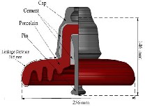
The investigations were carried out on three types of grad- ing rings, which were denominated by type-R1 to type-R3, respectively. Technical parameters of the simulated porcelain insulator and the mentioned rings are introduced in Fig. 1 and Fig. 2 , respectively.
Fig. 1. Geometrical characteristics of each porcelain insulator unit.
It must be mentioned that corona ring type R3 is consi- dered as compound of type R2 installed at the energized side and corona ring R installed at the grounded side.
The analysis presented in this paper was carried out using commercially available program Maxwell 3-D (Ansoft Corpora- tion), which is a FEM based software. Finite element method (FEM) was introduced in 1960, and initially applied in electrical engineering in 1965. Now FEM is being widely used in electrical engineering as a main numerical calculation method for quantify- ing and optimizing the performance of an insulator under electro- magnetic fields [12].
The finite element method for any problem consists of, basical-
ly, discretizing the solution domain into a finite number of ele- ments, deriving governing equations for a typical element, as- sembling of all elements in the solution domain, and solving the system of equations.
High voltage apparatus, including outdoor insulators, lie in the domain of the electrostatics application modes. The 'statics' im- plies that the time rate of change is slow, and that wavelengths are very large compared to the size of the domain of interest, in this case an outdoor insulator [13].
The boundary problem of the 3-D electrostatic-field FEM is
expressed as (1) with being the electric potential [13].
2 2 2
x 2 y 2 z 2
0 B1
(a)
S 0 0 B2
1 2 , 1 1 2 2 B3
(1)
n n
S n dS
0, S i
i B4
(b)
![]()
where boundary condition B1 is true in the whole region, B2 is known potential boundary, B3 is the boundary condition on the interface of different mediums and B4 is floating potential
boundary. φ0 is 230 / 3 kV on the high voltage terminal, con- ductor and corona ring, and 0 V on the lower voltage terminal and iron tower. Cap and pins with unknown potentials must be set as floating potential boundaries. For high voltage insu- lator string problems considering effects of tower and conduc- tor, there is no symmetry plane.
For better studying of voltage distributions all values of vol-
tages was normalized as following: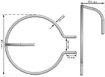
%Ui
![]()
Ui
230 / 3
*100
(2)
(c)
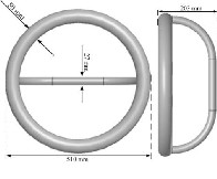
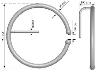
Fig. 2. Different Corona rings
(a) Corona ring R1 (b) Corona ring R2 (c) Corona ring R
where Ui is the voltage of i-th unit in kV and %Ui is the normalized voltage of the same unit in %.
IJSER © 2012
The research paper published by IJSER journal is about Optimal Corona Ring Selection for 230 kV Ceramic I-string Insulator using 3D Simulation 3
ISSN 2229-5518
Fig. 3 shows the thorough three-dimensional model of the cap-and-pin insulator string structure consisting of 13 units, which is utilized for the suspension of 230kV overhead trans- mission lines.
Simulation studies cover electric field and voltage distribu- tion calculation in the vicinity of insulator string. The equipo- tential contours around a 230-kV string insulator consisting of
13 insulator units are shown in Fig. 4.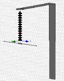
Fig. 3. Model used for both simulation and experiments with simplified tower model.
between the scales of zero to eleven times longer than the in- sulator string length consisting of 13 units. The effects of three different corona ring types on the potential distribution along the insulator string are presented in Section 4.3. It should be noted that in the simulation procedure the first insulator unit was considered the unit whose location is near the energized side.
4.1 Effect of conductor length
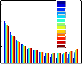
Potential distributions along the insulator string consisting of 13 units for various conductor lengths are presented as a bar chart in Fig. 5. Simulation results show that the influence of conductor lengths on the voltage distribution decreases as the conductor length increases [9]. The differences can be neg- lected (<0.5 %) for the scale of 7-times of string length and above.
As can be seen, the difference between results with and with-
out conductor effect is too high. Thus hereafter a model of con- ductor is included in all simulations.
Scale = 0
28 Scale = 0.5
Scale = 1
24 Scale = 2
Scale = 3
20 Scale = 4
Scale = 5
16 Scale = 6
Scale = 7
Scale = 8
12 Scale = 9
Scale = 10
8 Scale = 11
4
0
1 2 3 4 5 6 7 8 9 10 11 12 13
Insulator Number
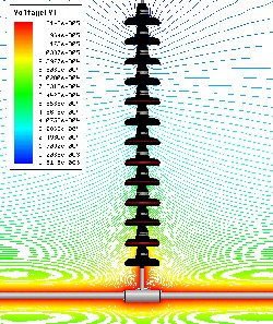
Fig. 5. Potential distributions along the insulator string for various co n-
ductor lengths.
Fig. 4. Equipotential contours around a 230-kV insulator string.
A group of simulations were carried out for investigating the effect of different factors on string performance. In Section
4.1, the effects of number of insulator units are presented. In section 4.2, the length of the conductor was chosen to vary
4.2 Effect of Number of Insulator Units
As mentioned before, because of the stray capacitances ex- isting between the insulator discs, the conductor and the tower, the voltage distribution along the insulators is unba- lanced so that, the insulator units closer to the conductor are more highly stressed. One way to make the potential distribu- tion more uniform is increasing the numbers of insulators.
Fig. 6. presents the potential distribution along a suspen- sion insulator string for various insulator numbers from 13 to
16 units. It must be noted that the length of the conductor used for this simulation of the model, was chosen to be equal to the insulator length.
It is obvious that the bottom insulator which is connected
to high voltage conductor bears the maximum voltage drop
and maximum electric field which makes it first vulnerable for
damage and subsequent breakdown. As can be seen, when the
number of units increased from 13 to 16, the electric potential
over the unit nearest to the line conductor decreased from
19.98 % to 19.64 %, which is not a significant reduction.
IJSER © 2012
The research paper published by IJSER journal is about Optimal Corona Ring Selection for 230 kV Ceramic I-string Insulator using 3D Simulation 4
ISSN 2229-5518
20 n= 13
18 n= 14 n= 15
16 n= 16
14
12
10
8
6
4
2
5

x 10
15
10
5
0
X=0 , Y=0
X=120, Y=0
X=250, Y=0
2 4 6 8 10 12 14 16
Insulator Number
0 500 1000 1500 2000
Insulator String Length (mm)
Fig. 6. Potential distribution along a suspension insulator string for vari- ous number of insulator.
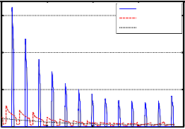
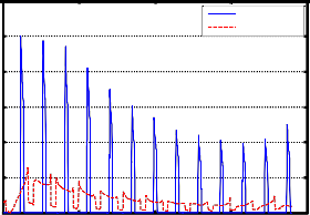
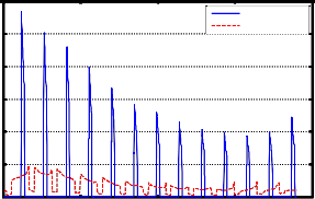
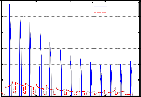
For the electric field results, two series of graphs are ob- tained. The first series includes lines that have constant Y = 0 and the Z-coordinate gradually increases at constant x- coordinates. The second series includes lines that have con- stant X = 0 and gradually draw away, both from insulator and the conductor at constant y-coordinates. The electric field dis- tribution for the insulator string containing 13 units along lines which have constant X = 0 and constant Y = 0 are shown in Figs. 7 and 8, respectively.
The electric field strength along the lines (X = 120 mm, Y =
0 mm) and (Y = 0 mm, X = 120 mm), which abut the outside
sheds of the insulators, goes sharply down when the line goes
through the porcelain sheds. This is for the reason that the
value of the dielectric constant of the porcelain is greater than
the dielectric constant of the surrounding air. Consequently,
there is a noticeable decrease in the electric field strength at
the region of porcelain [12]. In addition, the maximum values
of the electric field of the series with constant Y = 0 are slightly
Fig. 8. Electric field distribution for the insulator string along lines which have constant y = 0.
4.3 Effect of Corona Ring Types
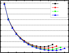
In this section, to inspect the corona ring effect on voltage distribution, three different corona ring types, as introduced in section 2, were considered. It is predictable that the usage of corona ring in an insulator string will remarkably decrease the voltage percentage on the lowermost insulators and will slightly increase the voltage sharing on the uppermost insula- tors.
Fig. 9. shows the effects of corona rings R1, R2, R3 on po- tential distribution across the 13-units insulator string. As it can be observed, corona ring R1 had the most significant effect on improving the potential distribution, so that it reduces the voltage across the first unit from 19.98 to 12.02 % due to the best placement of the ring R1 in its vertical plane, which had about 40 % reduction.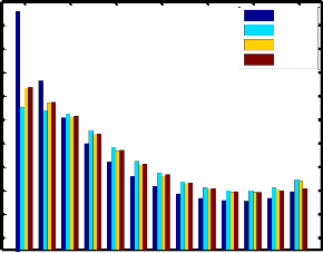
higher than the series with constant X = 0 owing to the influ- 19
ence of conductor for the latter one. 17
5 15
No Ring
Type R1
Type R2
Type R3
x 10
15
10
5
0
X=0, Y=0
X=0, Y=120
X=0, Y=250
0 500 1000 1500 2000
Insulator String Length (mm)
Fig. 7. Electric field distribution along lines which have constant x = 0.
Fig. 9. Effects of corona rings R1, R2, R3 on potential distribution across the 13-units insulator string.
Electric field distribution results under mentioned ring types along the lines with constant y = 0 mm are given in Figs.
10, 11 and 12 which approve the results obtained from voltage
IJSER © 2012
The research paper published by IJSER journal is about Optimal Corona Ring Selection for 230 kV Ceramic I-string Insulator using 3D Simulation 5
ISSN 2229-5518
distribution.
5
12 x 10
10
8
6
4
2
0
X= 0 , Y=0
X=120, Y=0
and y=0 reduced from about 16 kVrms/cm to 10, 11.4 and 11.5 kVrms/cm for corona rings R1, R2 and R3, each. It must be noted that the effect of corona ring installation on field reduc- tion over the first unit was extremely more significant than increasing the insulator units, which led to at least a reduction about 28 %.
An attempt was done to understand the effect of various co- rona rings, which are more utilized in Iran 230 kV transmis- sion line, on the voltage and electric field distribution of 230- kV insulator strings. 3-D simulations were carried out using software based on FEM and the effects of nonsymmetrical components such as tower and conductor is taken into ac-
0 500 1000 1500 2000
Insulator String Length (mm)
Fig. 10. Electric field distribution for corona ring R1 along the lines with constant y = 0 mm.
5
12 x 10
X= 0 , Y=0
10 X=120, Y=0
8
6
4
2
0
0 500 1000 1500 2000
Insulator String Length (mm)
Fig. 11. Electric field distribution for corona ring R2 along the lines with constant y = 0 mm.
5
12 x 10
X= 0 , Y=0
10 X=120, Y=0
8
6
4
2
0
0 500 1000 1500 2000
Insulator String Length (mm)
Fig. 12. Electric field distribution for corona ring R3 along the lines with constant y = 0 mm.
For instance, the maximum electric field along the line x=0
count. Also, the effects of some secondary factors including
variation in number of insulator units and conductor length have been evaluated.
When investigating the simulation results corona ring R1
had the best effect on improving insulator string performance
by virtue of the best placement of the ring R1 in its vertical
plane and also its optimal configuration. On the whole, the
introduced experimental method can be used for other insula-
tor and corona ring types, leading to trustworthy results, pro-
viding the HV overhead lines planners to design them at a
reliable insulation level.
[1] Ashouri M., Mirzaie M. and Gholami A., "Calculation of Voltage Distribution along Porcelain Suspension Insulators Based on Finite Element Method" Journal of Electric Power Components and Systems, Vol. 38, pp. 820-831, May
2010.
[2] Andrew J. Phillips, John Kuffel and Anthony Baker, "IEEE Taskforce on Elec- tric Fields and Composite Insulator, Electric Fields on AC Composite Trans- mission Line Insulators", IEEE Transactions on Power Delivery, Vol. 23, pp.
823-830, 2008.
[3] T. Doshi, R. S. Gorur and J. Hunt, "Electric Field Computation of Composite Line Insulators up to 1200 kV AC", IEEE Transactions on Dielectrics and Electrical Insulation, Vol. 18, pp. 861-867, 2011.
[4] S. M. Al Dhalaan, and M. A. Elhirbawy, ―Simulation of voltage distribution
calculation methods over a string of suspension insulators‖, 2003 IEEE PES
Transmission and Distribution Conference and Exposition, Vol. 3, pp. 909 -
914, 2003.
[5] E. Izgi., A. Inan, and S. Ay, ―The analysis and simulation of voltage distri- bution over string insulators using Matlab/Simulink‖, Electric Power Com- ponents and Systems, Vol. 36, No. 2, pp. 109–123,2008.
[6] W. McAllister, ―Electric fields and electrical insulation‖, IEEE Transactions
on Dielectrics and Electrical Insulation, Vol. 9, No. 5, pp. 672-696, 2002.
[7] H. Wei, Y. Fan, W. Jingang, Y. Hao, C. Minyou, and Y. Degui, ―Inverse
application of charge simulation method in detecting faulty ceramic insula- tors and processing influence from tower‖, IEEE Transactions on Magnet- ics, Vol. 42, No. 4, pp. 723-726, 2006.
[8] N. Morales, E. Asenj, and A. Valdenegro, ―Field solution in polluted insula- tors with non-symmetric boundary conditions‖, IEEE Transactions on D i- electrics and Electrical Insulation, Vol. 8, No. 2, pp. 168 -172, 2001.
[9] T. Zhao, and M. G. Comber, ―Calculation of electric field and potential distribution along nonceramic insulators considering the effects of condu c- tors and transmission towers‖, IEEE Transactions on Power Delivery, Vol.
15, No. 1, pp. 313-318, 2000.
IJSER © 2012
The research paper published by IJSER journal is about Optimal Corona Ring Selection for 230 kV Ceramic I-string Insulator using 3D Simulation 6
ISSN 2229-5518
[10] Sh. M. Faisal, ―Simulation of Electric Field Distribution on Ceramic Insula- tor Using Finite Element Method‖, European Journal of Scientific Research, Vol.52, No.1, pp.52-60, 2011.
[11] B. S. Reddy, N. A. Sultan, P. M. Monika, B. Pooja, O. Salma and K. V.
Ravishankar, ―Simulation of potential and electric field for high voltage ce- ramic disc insulators‖, International Conference on Industrial and Informa- tion Systems (ICIIS) 2010, Indian Institute of Science, Bangalore, India, pp.
526 - 531
[12] F. YaDong, W. Xishan, Z. FiYu, “Simulation of Electric Field Distribu- tion of Composite Insulator”, Proceedings of the 2005 XIVth Interna- tional Symposium on High Voltage Engineering, Tsinghua Universi- ty, Beijing, China, August 25-29.
[13] J. He, J. Hu, Sh. Gu, B. Zhang and R. Zeng, “Analysis and Improve- ment of Potential Distribution of 1000-kV Ultra-High-Voltage Metal- Oxide Arrester”, IEEE Transactions on Power Delivery, Vol. 24, No.
3, pp. 1225-1233, 2009.
IJSER © 2012