International Journal of Scientific & Engineering Research, Volume 4, Issue 8, August-2013 1166
ISSN 2229-5518
OFDM Modulator for Wireless LAN (WLAN)
standard
Madhavi B Dubal., Prof S.A.Shirsat.
Abstract— Multicarrier modulation is required for wireliess communication system.OFDM is multicarrier modulation which provides good spectral efficiency and eliminates intersymbol interference and intercarrier interference.Proposed work is to simulate OFDM modulator for IEEE802.11a standard.OFDM modulator is simulated using Simulink tool from Matlab 2010b and System generator tool from Xilinx 12.2. and implemented on FPGA board.Sytem performance is evaluated as BER vs SNR using AW GN noise channel and Multipath Rician Fading Noise channel .
Index Terms - OFDM, FPGA,BER ,SNR,IEEE802.11a,ICI,ISI.
—————————— ——————————
INTRODUCTION
OFDM allows high speed for wireless communications. OFDM could be considered either a modulation or multiplex- ing technique, and its hierarchy corresponds to the physical and medium access layer. A basic OFDM system consists of a QAM or PSK modulator/demodulator, a serial to parallel / parallel to serial converter, and an IFFT/FFT module. FFT re- quires intensive calculation so OFDM modulator has been implemented on FPGA.FPGA provides less computationtime. This paper divides the work in VI sections; Section I presents the introduction; Section II presents the Related Work; Section III gives brief introduction of the Std.IEEE802.11a and funda- mentals of OFDM. Section IV gives the block diagram and explanation of each block. Sections V explain the implementa- tion and result and section VI discuss the conclusion.
1 RELATED WORK
Author [1] has implemented OFDM transmitter for IEEE
802.11a standard only. This work uses System generator and
Simulink. This work does not focus on suitability of FPGA for
IF processing
Author [2] has implemented enhanced IEEE802.11a MAC lay-
er which is applied to wireless LAN for Multimedia services
Author[3] has discussed detailed simulation of different
OFDM systems with different constellation mapping schemes
will be obtained using MATLAB-2011 program to study the effect of various design parameters on the system perfor- mance.
Author [4] has discussed a multiple carrier modulation tech- nique known as OFDM (Orthogonal Frequency Division Mul-
tiplex). It focuses on problems that are specific for its use in the future mobile multimedia communications (MMC) in the range of 60 GHz.
Author [5] has implemented a data scrambler, convolution encoder, data interleaver and BPSK modulator for WLAN
802.11a transmitter, it also presents the synthesis and simula- tion results for the same using Xilinx CPLD XA9536XL-15- VQ44.3 Std.802.11a & OFDM Fundamentals
3.FUNDAMENTALS OF OFDM AND IEEE802.11A
STANDARD
3.1 THE STANDARD IEEE 802.11A
The IEEE 802.11 specification is a wireless LAN (WLAN) standard it allows frequency band of 5GHz. IEEE802.11a frame format contains eight carriers are spaced across 200
MHz in the lower spectrum (5.150 - 5.350 GHz) and four carri-
ers are spaced across 100 MHz in the upper spectrum (5.725 -
5.825 GHz). The channels are spaced 20 MHz apart, which
allows for high bit rates per channel. Figure 2 shows the IEEE
channel scheme.
Figure1. IEEE 802.11a channel scheme
IEEE802.11a contains preamble data field and signal field.The first field of the PLCP header is called the preamble. The pre- amble consists of 12 symbols, which are used to synchronize the receiver. The second field is the signal field. The signal field is used to indicate the rate at which the OFDM symbols of the PSDU payload are transmitted.Data field data which is transmitted.
3.2 OFDM FUNDAMENTALS
OFDM is multi-carrier modulation and multiplexing tech- nique. OFDM contains 52 subcarriers per channel in the 5- GHz band. Out of these channels, only 48 carry actual data.
IJSER © 2013 http://www.ijser.org
International Journal of Scientific & Engineering Research, Volume 4, Issue 8, August-2013 1167
ISSN 2229-5518
The remaining four subcarriers are used as pilot subcarriers, which assist in phase tracking for coherent demodulation.
Table 1 shows the Physical layer parameters of OFDM Modula-
tor.
Table 1 Physical layer parameters [2]
Parameter | Value |
NSD : Number of data subcarriers | 48 |
NSP : Number of pilot subcarriers | 4 |
NS : Number of subcarriers, total | 52(NSD + NSP) |
∆F : Subcarrier frequency spacing | 0.3125 MHz |
TFFT : IFFT/FFT period | 3.2 µs (1/∆F) |
TPREAMBLE : PLCP preamble duration | 16 µs (TSHORT + TLONG) |
TSIGNAL : Duration of the SIG- NAL BPSK-OFDM symbol | 4.0µs(TGI+TFFT) |
TGI : GI duration | 0.8µs (TFFT /4) |
TGI2 : Training symbol GI duration | 1.6 µs (TFFT /2) |
TSYM : Symbol interval | 4µs (TGI + TFFT) |
TSHORT :Short training sequence duration | 8µs(10 ×TFFT /4) |
TLONG : Long training sequence duration | 8 µs (TGI2 + 2×TFFT) |
The OFDM signal is generated through the use of complex signal processing such as fast Fourier transforms (FFTs) and inverse FFTs in the transmitter and receiver. One of the ad- vantage of OFDM is it eliminates the intersymbol interference in a channel. Also OFDM is spectrally efficient.
4 SYSTEM BLOCK DIAGRAM
Figure 2 shows Block diagram of OFDM modulator for IEEE
802.11a standard.
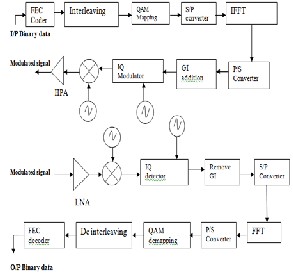
Figure.2: Block diagram of OFDM transreceiver.
The OFDM Physical layer (PHY) transmitter contains follow- ing blocks such as FEC Coder/decoder, Interleav-
ing/deinterleaving, IFFT/FFT, Guard Interval (Cyclic Pre- fix)addition /GI Removal.
4.1 FEC CODER/DECODER
This is channel encoder which encodes the digital data at the transmitter side and decodes at the receiver side with cod- ing rate R = 1/2, 2/3, or 3/4, corresponding to the desired data rate.
4.2 INTERLEAVING/DEINTERLEAVING
Interleaving is applied to randomize the occurrence of bit er- rors. Due to interleaving coded bits are permuted in a certain way, which makes sure that adjacent bits are separated by several bits at the transmitter side and vice versa operation take place at receiver side.
4.3 PSK AND QAM MAPPER/DEMAPPER
These block performs the constellation mapping and de- mapping of input binary data according to modulation schemes such as BPSK, QPSK, 16-QAM and 64-QAM. QAM is used extensively as a modulation scheme for digi- tal telecommunication systems. Arbitrarily high spectral effi- ciencies can be achieved with QAM by setting a suitable con- stellation size, limited only by the noise level and linearity of the communications channel
4.4 IFFT/FFT
By using this block the symbol is modulated onto 52 subcarri- ers by applying the Inverse Fast Fourier Transform (IFFT) and demodulated by using Fast Fourier Transform at receiver side to recover 52 carrier values.
4.5 GI ADDITION/REMOVAL
The inter symbol interference is almost completely eliminated by introducing a guard time for a each OFDM symbol. The guard time is chosen larger than the expected delay spread such that multipath components from one symbol cannot in- terfere with the next symbol.
4.6 IQ MODULATOR
Using an IQ modulator, the signal is converted to analog, which is up converted to the 5 GHz band, amplified, and transmitted through the antenna.
5 IMPLEMENTATION
5.1 IMPLEMENTATION
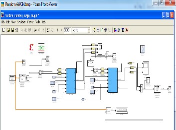
OFDM was simulated using Xilinx System Generator which runs under MATLAB Simulink for verification.
IJSER © 2013 http://www.ijser.org
International Journal of Scientific & Engineering Research, Volume 4, Issue 8, August-2013 1168
ISSN 2229-5518
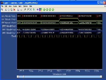
The waveform on wavescope shows the output of modulated and demodulated signal.When Vout signal goes high then output waveforms are observed which isshown in figure 4.
Figure. 3 Implementation of OFDM transreceiver.
In the transmitter random data source generates the infor- mation signal. Then QAM modulator block from simulink maps this signal into constellation diagram using 64QAM. Output of QAM modulator is given to complex to real imag block which converts complex signal into real and imaginary signal. This complex signal is given to IFFT block where IFFT block modulates this signal. Then AWGN channel add noise in modulated signal gives to FFT block. FFT block demodu- lates this signal to recover subcarriers. Complex to real imag block converts this real and imaginary signal into complex signal. Then this complex signal is given to QAM demodulator which demapps the signal into information signal.
Mcode: - It calls a Matlab .m file and executes it inside the simula-
tion.
5.2 DESCRIPTION OF SYSTEM GENERATOR BLOCKSET
Gateway In: - It makes an approach to the behaviour of a sig- nal in hardware.
Gateway Out: - It returns an approach of the behaviour of a signal in hardware to the simulation mode
System Generator: - It provides control of the system and simulation parameters. It is used to invoke the generated VHDL code
Resource Estimator: - It presents the resources of the device used in the simulation of the circuit like LUT’s, IOB’s etc.
Work scope: - Similar type as that of Simulink Scope which shows analog/digital waveform within hardware system.
In OFDM modulator for random data source Bit error rate versus signal to noise ratio performance is calculated using AWGN and Multipath Rician fading nose channel.
Figure 4: OFDM Modulated and demodulated waveform on
Wavescope.
Figure 5 shows the RTL schematic which gives the idea of internal connection of difeernt block which are simulated us- ing system generator tool
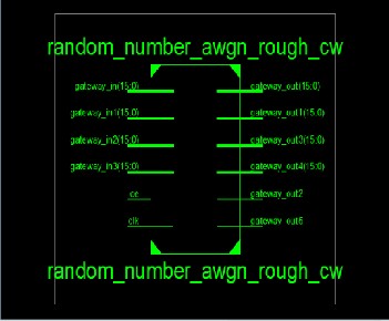
Figure.5: RTL Shematic of OFDM Modulator and Demodula- tor
The Xilinx Resoource Estimator block provides fast estimate of FPGA resources required to implement a system generator sub system or model.These estimates are computed by invoking block-specific estimator for Xilinx blocks,and summing these values to obtain aggregated estimator of flip-
IJSER © 2013 http://www.ijser.org
International Journal of Scientific & Engineering Research, Volume 4, Issue 8, August-2013 1169
ISSN 2229-5518
flops(FFs),block memories(BRAM),18x18 multipliers tristate buffers,and I/Os .
Table2 shows the Resource Estimation of OFDM Modulator and Demodulator
Table 2 Resource Estimation of OFDM Modulator and
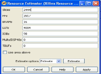
Demodulator.
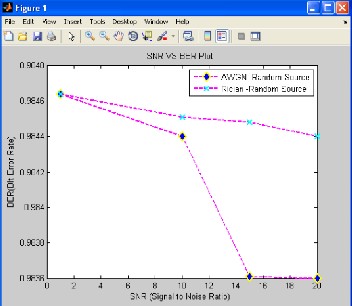
Figure 5: BER Vs SNR performance for AWGN and Multipath
Rician fading noise channel.
The device utilization summery of OFDM modulator and de- modulator using ISE 12.1 simulator is discussed in table 3. Target device selected for reference is Vertex 5.Device utilization sum- mary gives the idea of FPGA resources required to implement a system generator sub system or model on specific target device.
Table 2. Device utilization summery of BPSK Demodulator
(Target Device-Vertex 5 xc5xs50t-ff136, Xilinx ISE design Suite-
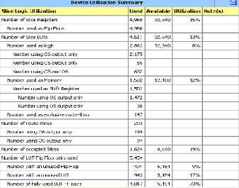
12.1)
Figure 6. shows the BER Vs SNR graph for OFDM modem is evaluated the performance parameter using AWGN channel and Multipath Rician Fading noise channel. Simulation graph shows that, when SNR increases BER decreases.
From the result for both noise channel if signal to noise ratio goes on increasing then BER goes on decreasing. AWGN Channel has good performance as compare to Multipath Ri- cian fading noise channel.
7. CONCLUSION AND FUTER SCOPE
7.1 CONCLUSION
OFDM modulator is simuklated for different noise channel if signal to noise ratio goes on increasing then BER goes on de- creasing. AWGN Channel has good performance as compare to Multipath Rician fading noise channel.
7.2 FUTURE SCOPE
The next goal of this work is to implement the OFDM modula- tor using FPGA device and to use it for applications.
REFERENCES
[1] Joaquin Garcia,Renu Cumplido “On the design of an FPGA-Based OFDM modulator for IEEE 802.11a” IEEE Com- puter, pp. 19–21, September 7-9,2005.
[2] Anibal Luis Intini, “Orthogonal Frequency Division Multi- plexing For Wireless Network” in Proc 7th International OFDMWorkshop 2002, Dec 2000
[3] R. Van Nee, R. Prasad, “OFDM For Wireless Multimedia
Communications,” Artech Hause Publishers, 2000, ch. 1, pp.
20– 25.
[4] S. Gifford, J. E. Kleider, S. Chuprun, “Broadband OFDM
IJSER © 2013 http://www.ijser.org
International Journal of Scientific & Engineering Research, Volume 4, Issue 8, August-2013 1170
ISSN 2229-5518
using 16-bit precision on a SDR platform,” in Proc. IEEE Mili- tary Communications Conference, Arizona USA, pp. 180–184, October 2001.
[5] M.A.Mohmad’, “Study Of Performance Parameters Effects On OFDM Systems” IJCSI International Journal of Computer Science Issues, Vol. 9, Issue 3, No 2, May 2012.
[6] Dusan Matix’,” OFDM as a possible modulation technique for multimedia applications in the range of mm waves” Intro- duction to OFDM, II edition.
[7] Dr. Pradeep B. Mane, Shobha N. Pawar’,” Synthesis and
Simulation of Data Scrambler,
Convolution Encoder, Data Interleaver and BPSK Modulator for WLAN (802.11a) Base band Chip” International Journal of Engineering and Innovative Technology (IJEIT) Volume 1, Issue 3, March 2012.
[8] J. Mitola, “Software radios-survey, critical evaluation and
future directions”, Telesystems Conference, pp. 13–15, May.
1992.
[9] Y. Kim, H. Jung, H. Ho Lee and K. Rok Cho and F. Harris ,
“MAC Implementation for IEEE 802.11 Wireless LAN”, ATM
(ICATM 2001) and High Speed Intelligent Internet Symposi-
um, 2001. Joint 4th IEEE International Conference on, pp. 192–
195, Apr. 2001.
IJSER © 2013 http://www.ijser.org