International Journal of Scientific & Engineering Research, Volume 4, Issue 8, August-2013 1108
ISSN 2229-5518
Novel U-shape and H-shape Rectangular Microstrip Patch Antenna for Ultra Wide Band application
Dipika Nayak1 , Alok Agarwal2
1M-Tech student (ECE), Lingaya’s University, Faridabad (Haryana), India,
2 Department of ECE, Lingaya’s University, Faridabad (Haryana), India,
1email2dipika@yahoo.com ,2alokagarwal26@yahoo.com,
Abstract: - This paper introduces a novel U-shape and H-Shape microstrip patch antenna for UW B application using single layer structure. In this paper one U-shape design and another H-shape design are proposed which gives enhanced bandwidths with 95.26% and 139.10%. The simulation results show that the antenna offers excellent performance for UW B application ranging (18.8 GHz to 53 GHz) and (11.1 GHz to 61.81
GHz).The electromagnetic simulation of the proposed antenna has been carried out using Ansoft HFSS software. Radiation characteristics of microstrip patch antenna like VSW R, return loss, smith chart and directivity are evaluated using this software.
Index Terms: - Bandwidth, microstrip antenna, return loss, VSW R.
—————————— ——————————
. 1. INTRODUCTION
MICROSTRIP antennas are widely utilized in many commercial applications such as mobile, radio and wireless communication. In recent years the demand for broad-band antennas has increased for use in high frequency and high speed data communication. In addition, applications in present day mobile communication systems usually require smaller antenna size in order to meet the miniaturization requirements of mobile units. A small antenna size requirement is one of the important factors in portable mobile communication systems. Thus size reduction and bandwidth enhancement are becoming major design considerations for practical applications of microstrip antennas. For this reason, studies to achieve compact and broadband operations of microstrip antennas have greatly increased. In addition microstrip antennas are manufactured using printed circuit technology, so that mass production can be achieved at a low cost. Most recent applications in UWB are target precision locating, sensor data collection and tracking applications.
Conventional microstrip antenna in general have a conducting patch printed on a grounded substrate and have the attractive features of low profile, light weight, easy fabrication and conformability to mounting. However microstrip antennas inherently have a narrow bandwidth [1-8] and bandwidth enhancement is usually demanded for practical applications.
Fig.1 shows the U-shape rectangular microstrip patch antenna of proposed design 1. The patch is printed on
inexpensive FR4 (copper-cladded plate) having dielectric constant (Єr) of 4.4, loss tangent tan δ = 0.02 and height 1.6 mm. The strip line feed technique is used for feeding the microstrip patch antenna. The step frequency = 0.01 GHz, operating frequency f0 = 35.9 GHz, frequency range = 18.8
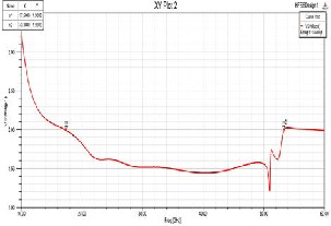
GHz to 53 GHz, length of patch L = 12 mm, width of patch W = 22 mm. Fig. 2 shows design in HFSS platform. Fig. 3 shows the variation of return loss with frequency for proposed design 1. Fig. 4 shows the variation of VSWR with frequency for proposed design 1. Fig. 5 and 6 shows the radiation pattern for proposed design 1. Fig.7 shows the impedance loci for proposed design 1. The bandwidth for proposed design 1 is coming out to be 95.26 %. It is observed that the proposed design 1 gives sufficiently high bandwidth for UWB applications.
Table: 1 Design Parameters (in mm) for proposed design 1 and 2
Parameters | Wp | Lp | a | b |
Design-1 | 22 | 12 | 4 | 4 |
Design-2 | 22 | 12 | 4 | 4 |
Table-1 shows the design parameters for proposed design-
1 and design-2
IJSER © 2013 http://www.ijser.org
International Journal of Scientific & Engineering Research, Volume 4, Issue 8, August-2013 1109
ISSN 2229-5518
Fig.1. U- shape rectangular microstrip patch antenna of proposed design 1
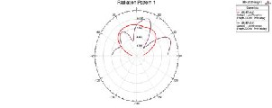
Fig.4.Variation of VSW R with frequency for proposed design 1
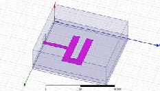
Fig.2 U-shape design of proposed antenna design-1
Fig.5.Radiation pattern-1 for proposed design 1
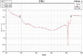
Fig.3. Variation of return loss with frequency for proposed design 1
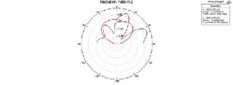
Fig.6.Radiation pattern-2 for proposed design 1
IJSER © 2013 http://www.ijser.org
International Journal of Scientific & Engineering Research, Volume 4, Issue 8, August-2013 1110
ISSN 2229-5518
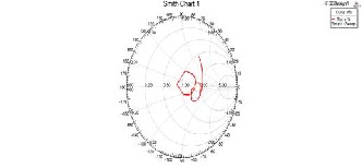
Fig.7 Impedance Loci for design 1
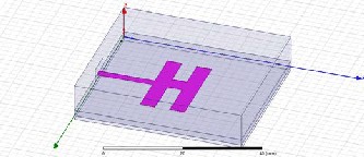
In Design-2 effort has been made to further enhance the bandwidth. Fig. 8 shows H-shape rectangular microstrip patch antenna of proposed design 2.
Fig.8. H- shape rectangular microstrip patch antenna of proposed design 2
In this proposed design 2, L= 12 mm and W= 22 mm is taken. The band is obtained on simulation frequency range
= 11.1 GHz to 61.81 GHz with operating frequency f0 =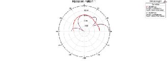
36.45 GHz. Fig.9 shows design in HFSS platform.Fig.10 shows the variation of return loss with frequency for proposed design 2. Fig. 11 shows the variation of VSWR with frequency for proposed design 2. Fig.12 shows the impedance loci for proposed design 2. Fig. 13 shows the radiation pattern for proposed design 2. The measured bandwidth for proposed design 2 is coming out to be
139.10 %, which is sufficiently high as compared with
conventional microstrip patch antenna of same design
parameter and other radiation characteristics are also
optimized, which can be utilized for UWB communication
applications.
Fig. 9 H-shape microstrip antenna of proposed design 2
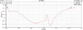
Fig.10. Variation of return loss with frequency for proposed design 2
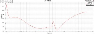
Fig.11.Variation of VSW R with frequency for proposed design 2
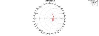
Fig. 12 Impedance Loci for design 2
IJSER © 2013 http://www.ijser.org
International Journal of Scientific & Engineering Research, Volume 4, Issue 8, August-2013 1111
ISSN 2229-5518
Fig.13. Radiation pattern for proposed design 2
The simulation results of the proposed antennas have been carried out by using finite element method, Ansoft HFSS software. For the U-shape rectangular microstrip patch antenna of proposed design 1, the bandwidth is coming out to be 95.26 %, whereas for the H-shape size microstrip patch antenna of design 2, the bandwidth is coming out to be
139.10%, therefore both the proposed designs give very good increment in bandwidth. These designs fulfill the demands of UWB applications.
[1]. Milligan, T. A., “Modern Antenna Design”, John Wiley & Sons, Hoboken, New Jersey, 2005.[3]Garg, R., P. Bhartia, I. Bahl, and A. Ittipiboon, “Microstrip Antenna Design Handbook”, Artech House, Boston, London, 2001.
[2]. Wong, K. L., “Compact and Broadband Microstrip Antenna”,
John Wiley & Sones, New York, 2002.
[3]. Kumar, G. and K. P. Ray, “Broadband Microstrip Antennas”,
Artech House, USA, 2003.
[4]. Ghassemi, N., M. H. Neshati, and J. Rashed-Mohassel, “Investigation of multilayer probe-fed microstrip antenna for ultra wideband operation,” Proceeding of Asia Pacific Microwave Conference (APMC 2007), 2135–2138, Bangkok, Thailand, Dec.
11–14, 2007.
[5]. Matin, M. A., B. S. Sharif, and C. C. Tesimenidis, “Probe fed
stacked patch antenna for wideband applications,” IEEE Trans.
Antennas Propagate., Vol. 55, No. 8, 2385–2388, Aug. 2007.
[6]. Ray, K. P., S. Ghosh, and K. Nirmala, “Multilayer multi
resonator circular microstrip antennas for broadband and dualband operations,” Microwave and Optical Technology Letters, Vol. 47, No. 5, 489–494, Dec. 2005.
[7]. Ghassemi, N., M. H. Neshati, and J. Rashed-Mohassel, “A multilayer multiresonator aperture coupled microstrip antenna for ultra wideband operations,” Proc. IEEE Applied Electromagnetic Conference 2007, Kolkata, India, December 19–20,
2007.
[8]. Zehforoosh, Y., C. Ghobadi, and J. Nourinia, “Antenna design
for ultra wideband applications using a new multilayer
structure,” PIER Online, Vol. 2, No. 6, 544–549, 2006
IJSER © 2013 http://www.ijser.org