International Journal of Scientific & Engineering Research, Volume 4, Issue 4, April-2013 272
ISSN 2229-5518
Brajesh Kumar Gupta , M.Tech Scholar
Department of Electronics and Communication Engg. National Institute of technology, Jamshedpur (India)
Associate prof. Rashmi Sinha Department of Electronics and Communication Engg. National Institute of technology, Jamshedpur (India)
![]()
Index Terms— Hamming code, Novel Hamming code, error-correction, error-detection, even parity check method, Redundancy bits, VHDL language, Xilinx ISE 9.2 Simulator
—————————— ——————————
![]()
For example, it needs 4 redundancy bits for a 7-bit data item and 6 redundancy bits for a 56-bit data stream. Let us say, the
7-bit data to be transmitted is 0111001. Then the 11-bit data
actually transmitted is 011P100P1PP, where the P’s refer to the Hamming bits that are to be calculated and interspersed at bit positions 1, 2, 4, & 8 (n = 0, 1, 2, 3) with the original data bits. The calculation of the Hamming bits is as illustrated below:
The Hamming bit at bit position 1 is selected such that there is even parity at bit positions 1, 3, 5, 7, 9, & 11 Thus the Ham-
ming bit at position 1 will be 1.
The Hamming bit at bit position 2 is selected such that there is even parity at bit positions 2, 3, 6, 7, 10, & 11 .Thus the Hamming bit at position 2 will be 1.
The Hamming bit at bit position 4 is selected such that there is even parity at bit positions 4, 5, 6, & 7 . Thus the Hamming bit at position 4 will be 1.
The Hamming bit at bit position 8 is selected such that there is even parity at bit positions 8, 9, 10, & 11. Thus the Hamming bit at position 8 will be 0
Thus the 11-bit data actually transmitted is 01101001111. For the calculation of Hamming bits at positions 1, 2, 4, & 8, even- parity checks were performed on 6, 6, 4, & 4 bits respectively. Thus a total of 20 bits are involved in the process of Hamming bits calculations. The error-detection and correction process in Hamming code is as illustrated in Table 1 Hamming code is normally used for transmission of 7-bit data item. Scaling it for larger data lengths results in a lot of overhead due to inter- spersing the redundancy bits and their removal later, It is not efficient for higher data bit
TABLE 1
ERROR DETECTION AND CORRECTION USING HAMMING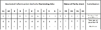
CODE
IJSER © 2013 http://www.ijser.org
International Journal of Scientific & Engineering Research, Volume 4, Issue 4, April-2013 273
ISSN 2229-5518
Suppose the received information is 01101011111, with an er- ror at bit position 5. There is no even parity error at bit posi- tions 8, 9, 10, & 11. So the status of parity check S3 is shown as T (true) in the table below. There is even parity error at bit positions 4, 5, 6, & 7. So the status of parity check S2 is shown as f (false). Similarly there is no even parity error at bit posi- tions 2, 3, 6, 7, 10 & 11 and even parity occurs at bit positions
1, 3, 5, 7, 9, & 11. So the status of parity check S1 is shown as T and S0 is shown as F. Interpreting F as 1 and T as 0 in the sta- tus of parity check, we find that the error is at bit position
0101 i.e. 5. Bit 5, which was received as 1, is corrected as 0.
Previous approach of Hamming coding [] is not efficient for error correction and detection of higher bit data items
![]()
Let us consider the same example. The 7-bit data to be transmitted is 0111001. The number of redundancy bits, ‘r’ to be appended to n-bit data is obtained such that the relation
is satisfied. The number of redundancy bits in this method is same as that for Hamming code for some values of n. But in some cases, it will be just one more redundancy bit than needed in the Hamming code[4][8][9]. For 7-bit data, the number of redundancy bits required will be 4. Then the 11-bit data actually transmitted is PPPP0111001, where the P’s refer to the redundancy bits that are to be calculated and appended at bit positions 8, 9, 10, & 11. The calculation of these bits in the proposed method is as illustrated below.
The bit at bit position 8 is selected such that there is even pari- ty at bit positions 1, 3, 5, 7 and bit position 8. Thus the bit at position 8 will be 0.
The bit at bit position 9 is selected such that there is even pari- ty at bit positions 2, 3, 6, 7 and bit position 9. Thus the bit at position 9 will be 1.
The bit at bit position 10 is selected such that there is even parity at bit positions 4, 5, 6, 7 and bit position 10. Thus the bit
at position 10 will be 1.
The bit at bit position 11 is selected such that there is even parity considering only the redundancy bits. Thus the bit at position 11 will be 0.
Thus the 11-bit data actually transmitted is 01100111001. For
the calculation of bits at positions 8, 9, 10, & 11, even- parity
checks were performed on 5, 5, 5, & 4 bits respectively. Thus a total of 19 bits are involved in the process of calculation of redundancy bits. The error-detection and correction process in the novel method is as illustrated in Table 2.
TABLE 2
ERROR DETECTION AND CORRECTION USING IMPROVED METHOD
TABLE 3
COMPARISON OF NUMBER OF BITS INVOLVED IN THE CALCULATION OF REDUNDANCY BITS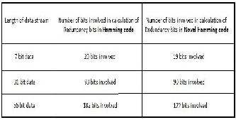
Suppose the received information is 01100011001, with an error at bit position 6. There is no even parity error at bit posi- tions 1, 3, 5, 7 & 8. So the status of parity check S0 is shown as T in the table below. There is even parity error at bit positions
2, 3, 6, 7 & 9. So the status of parity check S1 is shown as F. Similarly there is even parity error at bit positions 4, 5, 6, 7 &
10 and even parity occurs at bit positions 8, 9, 10 & 11. So the status of parity check S2 is shown as F and S3 is shown as T. Interpreting F as 1 and T as 0 in the status of parity check, we find that the error is at bit position 0110 i.e. 6. Bit 6, which was received as 0, is corrected as 1
As we increase the number of bits , pad to pad delay
decreases in Novel Hamming encoder and decoder with re- spect to the Hamming encoder and decoder. Which is shown below in TABLE 4 & 5
TABLE 4
COMPARISON OF PAD TO PAD DELAY FOR 7 & 31 BITS ENCODER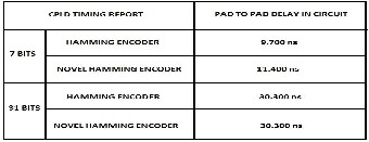
TABLE 5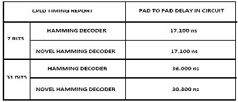
COMPARISON OF PAD TO PAD DELAY FOR 7 & 31 BITS DECODER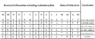
IJSER © 2013 http://www.ijser.org
International Journal of Scientific & Engineering Research, Volume 4, Issue 4, April-2013 274
ISSN 2229-5518
The calculation of redundancy bit is done by VHDL code written in Xilinx ISE 9.2 project navigator window. And simu- late this VHDL code by using Xilinx ISE 9.2 Simulator and get the value of redundancy bit for 7 bits Hamming encoder 0111 and for novel Hamming encoder 0110 which is shown in table
1 & 2 [5][6][7]. the encrypted data waveform of 31 bits for both Hamming code and novel Hamming code which is shown below
Hamming code
We are transmitting the information data of 31 bits
0110111001010000111011001101010( 31’h3728766A ) at Ham-
ming encoder output the data in encrypted form
0110111100101000011101110011001010010
(37’h0DE50EE652 ) . Now we generate the error at bit position
28 at the output of decoder we are able to collect the actual
information data
Novel hamming code
We are transmitting the information data of 31 bits
0110111001010000111011001101010( 31’h3728766A ) at Novel
Hamming encoder output the data in encrypted form is
Now we generate the error at bit position 20 at the output of
decoder we are able to collect the actual information data
HAMMING ENCODER
HAMMING DECODER ( ERROR AT BIT POSITION 28 )
NOVEL HAMMING ENCODER
NOVEL HAMMING DECODER ( ERROR AT BIT POSITION 20 )
IJSER © 2013 http://www.ijser.org
International Journal of Scientific & Engineering Research, Volume 4, Issue 4, April-2013 275
ISSN 2229-5518
An application of hamming code for error detection and correction with even parity check and odd parity check meth- od is that by this method there is no need to transmit data string again by transmitter at source end, if only single bit error is occurred by noisy channel because at destination end receiver can regenerate the original data string which was transmitted by transmitter at source end. Error detection and correction codes are used in many common systems including: storage devices (CD, DVD, DRAM), mobile communication (cellular telephones, wireless, microwave links), digital televi- sion, and high-speed modems (ADSL, xDSL) and also used to protect storage cell which is effected by SEUs
In the proposed improvement the redundancy bits are appended at the end of data bits. This eliminates the overhead of interspersing the redundancy bits at the sender end and their removal at the receiver end after checking for single-bit error and consequent correction, if any. Further the effort needed in identifying the values of the redundancy bits is lower in the proposed novel method. Hamming code is nor- mally used for transmission of 7-bit data item. Scaling it for larger data lengths results in a lot of overhead due to inter- spersing the redundancy bits and their removal later. In con- trast, the proposed method is highly scalable without such overhead. We see that there is only 7 bit overhead for a 56-bit data stream, which is much less compared to 4 bit overhead for a 7-bit data. Because of this feature this new method is suitable for transmission of large size data bit-streams as long as there is likelihood of at the most single-bit error during transmission.
[1] Data communication and networking , Behrouz A. Forouzan , 2nd edition Tata McGrawHill publication.
[2] Communication Networks, available at:
http://www.pragsoft.com/books/CommNetwork.pdf
[3] Xilinx ISE 8 Software Manuals and Help: http://www.eng.uwaterloo.ca/~tnaqvi/downloads/DOC/s d192/ISE8_1i_manuals.pdf
[4] W. Xiong, and D. W. Matolak, “Performance of Hamming Codes in Systems Employing Different Code Symbol Ener- gies,” IEEE Communications Society, pp. 1055–1058 [Wireless and Communications and Networking Conference (WCNC)].
[5] ISE 10.1 Quick Start Tutorial, available at http://www.xilinx.com/itp/xilinx10/books/docs/qst/qst.pd f
[6] VHDL (VHSIC hardware description language):
http://en.wikipedia.org/wiki/VHDL
[7] VHDL Tutorial, available at http://www.vhdl- online.de/tutorial
[8] T. Fujiwara et al., “Error Detecting Capabilities of the Shortened Hamming Codes Adopted for Error Detection in IEEE Standard 802.3,” IEEE Trans. Communications, vol. 37, no. 9, pp. 986–989, Sep 1989.
[9] W. W. Peterson and E. J. Weldon, Jr., Error-Correcting
Codes (2nd ed.). Cambridge, MA: MIT Press, 1972
Email : bkgupta8bu@gmail.com


Email : rsinha.ece@nitjsr.ac.in
IJSER © 2013 http://www.ijser.org