International Journal of Scientific & Engineering Research, Volume 5, Issue 2, February-2014 231
ISSN 2229-5518
Novel Flowchart for Design of Concrete
Rectangular Beams
Abdul Kareem M.B. Al-Shamma
Abstract— For flexural design of R/C rectangular section beams, there is a number of steps procedure and equations provided by ultimate strength design method according to ACI-code. The large number of equations and fork of solution steps causes a lot of confusion and boredom for student or designer. Checked the most common and authoritative textbooks that dealt with design of concrete structures according to (ACI-08). From long experience in teaching reinforced concrete material, show that the novel flowchart has more effect to give beginner engineering students speed to achieve design steps by less time and effort. This study focuses on flexural of straight beams due to the loads applied vertically, with single and double reinforcement, using SI units. Finally, I reached a simplified flowchart to track flexural design steps easily and conveniently.
Index Terms— Flexural design, Concrete flowchart, beams reinforcement, Stress distribution
—————————— ——————————
1 INTRODUCTION
n concrete structures, there are many textbooks and re- searches which dealt with how to get flexural and its rein- forcement. But, I have not found anybody to tell us a simple and easy way of how to calculate[1]. I've been personal suffer- ing in conveying information of this subject to the beginner
engineering students.
Concrete beams are widely used as a main member to con-
struct buildings in Iraq. STAAD/pro is widely used as a struc-
tural analysis and design program. Sometimes, to give design
more confidently, we need to compare the results of program
with the results of manual calculations.
Most common beams, which are rectangular section and T-
section, apply vertical loads (dead and live loads). Beams, like
that, will be subjected to the bending moment, shear force and torsional moment. This study focuses on beams of rectangular section considering bending moment only. Flexural created by bending moment, makes the beam in case of tension or com-
pression failure[2].

In case of tension failure, provided reinforcement ratio (ρ)
at tension zone is less than balanced reinforcement ratio ( . So that, steel will reach to the yield stress ( ) and strain ( ). While, concrete at compression zone has not yet reached to the
ultimate strain ( =0.003)[3][4].

In case of compression failure, provided (ρ) at tension zone is greater than ( . Concrete at compression zone will reach ultimate stress ( ) and strain ( , While steel has not yet reached ( . For each case, there is a number of design
equations derived. To identify those equations, textbooks can be reviewed for the principles of the design of reinforced con- crete[3][4].
Usually, longitudinal reinforcement is used for flexural strength in addition to flexural resist by concrete in compres- sion zone.
2 NOTATION
The terms in this list are used in the study [5][6].  = factored load per unit length of beam.
D = dead loads.
L = live loads.

 = factor relating depth of equivalent rectangular com- pressive stress block to neutral axis depth.
= applied factored moment at section, N.mm.
= specified yield strength of steel, MPa.
= specified compressive strength of concrete, MPa.
b = width of beam, mm.
d = distance from extreme compression fiber to centroid of tension reinforcement, mm.
 = distance from extreme compression fiber to centroid of compression reinforcement, mm.

C = distance from extreme compression fiber to neutral ax- is, mm.
= area of longitudinal tension reinforcement, 
= area of an individual bar, 
= area of longitudinal compression reinforcement,
= calculated stress in compression reinforcement, MPa.

ρ = reinforcement ratio in tension zone = .
.
= reinforcement ratio in compression zone =
= reinforcement ratio producing balanced strain condi- tions in case of single reinforcement.

 = reinforcement ratio producing balanced strain con- ditions in case of double reinforcement.
= maximum reinforcement ratio.
= minimum reinforcement ratio.
= maximum factored moment carried by 
= factored moment carried by compression reinforce-
ment.
3 PROPOSED METHOD AND THE APPLICATION
The study related to prepare flowchart (Fig.1) for design beams has the following properties:
• Concrete rectangular section, straight profile.
• Subjected vertical load (dead and live loads) concen- trated or distributed uniformly.
• Using ultimate strength design method with (ACI318-
08).
IJSER © 2014 http://www.ijser.org
International Journal of Scientific & Engineering Research, Volume 5, Issue 2, February-2014 232
ISSN 2229-5518
• Using equations with SI unit, consider beam in case of tension failure.
• Design of flexural with single or double reinforce- ment.
• Designer either is free to choose the appropriate depth or restricted by required depth.
Application Example

For rectangular concrete beam, given: b=300mm, d=350mm,

=62.5mm,  = 342 kN.m,
  =34.5MPa,
  = 414 MPa. Find
?.

Solution
IJSER © 2014 http://www.ijser.org
Fig.1. Proposed Flowchart for single reinforcement
International Journal of Scientific & Engineering Research, Volume 5, Issue 2, February-2014 233
ISSN 2229-5518
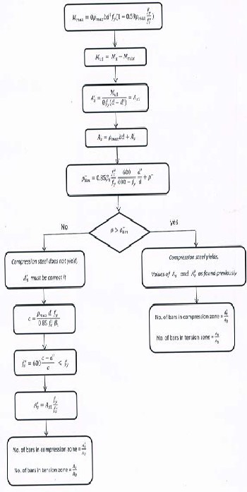
Fig.2. Proposed Flowchart for double reinforcement
sometimes to promote confidence can be calculated manually.
• Manually, proposed flowchart is a quick way to de- sign beams and one way slabs. Especially, when they are in accordance with the properties as mentioned in (ACI-08, 8.3.3).
• I noticed that the flowchart is considered clear and easy path. Students or designers accept it without confusion or boredom.
REFERENCES
[1] Choi, KK. , "Reinforced Concrete Structure Design Assistant Tool for Begin- ners", MSc thesis, Faculty of The School of Architecture, University of South California, 2002, pp.49.
[2] Purushottaman, p.," Reinforced Concrete Structural Elements-Behavior Anal-
ysis and Design", Tata McGraw-Hill publishing company limited, New Delhi, India, 1986.
[3] Hassoun, M. N., and Al-Manaseer, A., "Structural Concrete Theory and De- sign", 4th Edition, WILEY, USA, 2008.
[4] Nilson, A., Darwin, D., and Dolan, C., "Design of Concrete Structures", 13th
Edition, McGraw-Hill, USA, 2004.
[5] ACI Committee 318, "Building Code Requirements for Reinforced Concrete
(ACI 318-08)," American Concrete Institute, Detroit, 2008.
[6] Rama Rao, M.V.,Pownuk, A, " Stress distribution in a reinforced concrete flexural member with uncertain structural parameters", The university of Texas at El Paso, Department of Mathematical Sciences Research Reports Se- ries, Texas research Report No. 2007-05, EL Paso, Texas, USA, 2007.
4 CONCLUSION
From my academic and practical experience, has concluded the following points:
• By using STAAD/pro program, the researcher can recognize the value of moment at any section of the beam. Proposed flowchart is a simple and easy way to see how much steel area required for any moment. Obviously, the program has the facility to do so, but
IJSER © 2014
http://www.ijser.org