Inte rnatio nal Jo urnal o f Sc ie ntific & Eng inee ring Re se arc h Vo lume 3, Issue 3, Marc h -2012 1
ISS N 2229-5518
Neural adaptive control by state space system
UPFC (SSNN) for compensation of active
And reactive power
Bouanane Abdelkrim, Chaker Abdelkader, Addadi Zoubida, Amara Mohamed
Abs tract—in our present paper, w e present the effectiveness of the controller's electrical pow er f low Universal (unif ied pow er f low controller UPFC) w ith the choice of a control strategy. To evaluate the perf ormance and robustness of the system, w e proposed a hybrid control combining the concept of neural netw orks w ith conventional regulators vis -à-vis the changes in characteristics of
the transmission line in order to improve the stability of the electrical pow er netw ork.
Inde x Terms—UPFC system, adaptive control, neural netw orks, state space (SSNN).
—————————— ——————————
1 Intr oduction
ith the rapid development of the modern w or ld, the demand for electricity is grow ing and electrical installations ar e continually enhanced to meet these
r equir ements. The constr uction of new plants and new lines ar e necessary, but w ith FACTS devices, w e can solve some pr oblems while using the existing facilities.
Having highlighted the need for r apid contr ol of pow er flow in transmission line and the descr iption of the new concept of "FACTS" that was born to meet the incr easing difficulties in netw or ks including contr ol of the flow on the axes transport, w e ar e inter ested in our w or k to the contr oller 's electrical pow er flow universal [1], [2] (Unified Power Flow Contr oller UPFC).
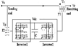
The UPFC consists of two switching converter , (ser ies
and shunt) (Fig. 1) and even this device is the union of a
parallel compensator and a ser ies compensator . It is capable of simultaneously and independently contr ol the active power and r eactive power . It can contr ol the thr ee parameters associated w ith pow er flow the line voltage, the impedance of the line and angle of tr ansport.
I t is ass ume d that the UPFC [3] s hown in Fig. 1 wa s plugge d into a s implifie d tra ns miss ion s ys tem, the a rriva l of the tra nsmiss ion line (Rece iving End). The two volta ge source inve rters cons tituting the UPFC a re connecte d togethe r through a common DC circuit. Two tra ns formers T1 a nd T2 a re use d to connect the two inve rters ,
————————————————
Boua na ne,, Addadi a nd Ama ra a re teachers in the depa rtment of electrica l engineering a t the University Dr. MOULAY TAHER,
in SAIDA, Algeria . (bouana nea bd@yahoo.fr)
Cha ker is professor in the depa rtment of electrica l engineering a t the
one seria l a nd one pa ra lle l to the tra nsmiss ion line .
Fig. 1 UPFC System Conf iguration
After all, this composition offers the UPFC's ability to contr ol the active pow er and r eactive power r egar dless of w her e:
- The series inverter (2) "Inverter2" per forms the pr incipal function of the UPFC by inj ecting an AC voltage in ser ies (AC) with an amplitude and a phase angle adjustable.
- The parallel UPS (1) "Inverter1 'r ole is to pr ovide or absorb the r eal pow er demanded by the inverter (2) to the connection (DC), as it can also pr oduce or absorb r eactive power according to demand, and pr ovide independent shunt compensation transmission line. The ser ies inver ter (2) pr ovides or absorbs the needed r eactive pow er locally pr oduced active pow er as a r esult of inj ecting a voltage in ser ies.
The simplified cir cuit of the contr ol system and compensation of UPFC is shown in (Fig. 2) modeling of this cir cuit is based on simplifying assumptions in the form of ideal voltage sour ces then the dynamic equations of the UPFC ar e divided into thr ee systems of equations: the equations of the ser ies branch, the equations of parallel br anch and those of the DC
ENSET in ORAN, Algeria. (chakeraa@yahoo.fr)
IJSER © 2012 http :// www.ijser.org
Inte rnatio nal Jo urnal o f Scie ntific & Eng ine e ring Rese arc h Vo lume 3, Issue 3, Marc h -2012 2
ISS N 2229-5518
cir cuit.
By applying Kirchhoff’s laws we will have the following equations.
dipb
![]()
dt
di![]()
- rp
L p
. i pb
![]()
1 . v
L p
- v cb
- v rb
(4)
UPFC
![]()
![]()
pc - rp . i![]()
1 . v
- v - v 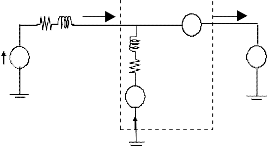
M odel of the line Is Ir
dt Lp pc
Lp pc cc
rc
r L Vc ~
Lp
W ith a tra ns forma tion marke r d, q we ha ve the sys te m of
equa tions (5):
~ Vs rp
di
pd ω . i
rp
- . i
1 v
- v - v
![]()
dt
Vp di pq![]()
pq Lp
rp
![]()
pd Lp pd cd
1
rd
(5)![]()
~ . i pd -
dt L
. i pq
L
v pq - v cq - v rq
(Sendin g) ip (Receivin g)
End End
p p
The ma trix form is give n as follows :
d i pd ![]()
rp l
i d
1 vsd
vcd
vrd
Fig. 2 Equivalent circuit of UPFC
![]()
p![]()
![]()
. p .
dt i pq
rp
lp i p q
l vsq
vcq
vrq
The mathematical model is given by the following equations:
di
By pass ing on the principle of ba la nce of powe r a nd ne glecting![]()
sa - r . i
![]()
1 v
- v - v
the losses of the converters . The DC volta ge V dc by the following
dt L
sa L sa ca ra
equa tion:![]()
![]()
disb - r . i
![]()
1 . v - v
- v
dv
c p p
(6)
dt L sb L
di
sb cb rb
(1)![]()
dt C vc
![]()
sc - r . i
![]()
1 . v - v
- v
He nce pe = vca isa + vcb isb + vccisc
dt L sc L
sc cc rc
The transformation of Par k aims to model this thr ee-phase
system (a, b, c) two-phase (d, q) as follows: (2)
pep = vpa ipa + vpb ipb + vpc ipc
W ith: pe: active powe r cons umption of the AC syste m
x d
cos ( t )
- s in ( t )
![]()
1 2
x a
Pe p: a ctive powe r injecte d by the s hunt inve rte r AC s ys te m
2
x q 3 cos ( t - 120 )
s in ( t - 120 )
1 2
x b
Applying the Pa rk tra ns forma tion on equa tion (6) we obta in:
o
cos ( t 120 )
s in ( t 120 )
![]()
1 2
c
W here x; ca n be a volta ge or current.
dv dc 3
(7)
![]()
v pd i p d v pq i pq - v cd i d - v cq i q
In our case, the component x0 is not seen as the power system is assumed to be symmetr ic. After the transformation of Par k, equation (1) is expr essed in the dq r efer ence by the equations:
di
dt 2 C v dc
The UPFC se ries a nd s hunt UPFC's a re ide ntica l in e very res pe ct. The comma nds use d to se t the inve rte r are the same for the s hunt inve rter.
4 Confi gur ation Contr ol Cir cuit:
sd . i
dt sq
![]()
- r . i
L sd
![]()
1
L
vsd
- v cd
- v rd
(3)
The ore tica lly the UPFC s hould be trea te d as a multiva riable s ys tem beca use both se ries a nd s hunt converte rs are![]()
disq . i dt sd![]()
- r . i
L sq![]()
1 v
L sq
- vcq
- vrq ![]()
connecte d from one s ide to the tra nsmiss ion line a nd the other s ide in continuous DC circuit a nd thus ea ch has two inputs a nd
The ma trix form of the dq a xis ca n be re writte n as follows :
two outputs . This for to facilita te the s ynthes is of se ttings ,
trea tme nt of the two converte rs will be done se pa ra te ly. The
d isd
![]()
r l
isd
1 vsd
vcd
vrd
poss ibility of this se pa ra tion is jus tifie d by two ma in fa ctors . Firs t,![]()
dt
![]()
r l.
![]()
l .
the coupling be tween the two conve rters of the tra ns miss ion line
isq
isq
vsq
vcq
vrq
is quite sma ll. Second, the dyna mic va ria tion of the voltage of DC
s ide of the continuum is domina te d by the para lle l conve rter.
The ma thema tica l mode l of the UPFC s hunt is give n s imilarly by the following e qua tions ![]() :
:
di
Control of the converte r in pa ra lle l UPFC is very s imilar to tha t of
the compe nsa tor SVC. So to control the flo w of active powe r in the tra ns miss ion line , the controlle r of the UPFC series mus t a djus t the a ngle of the phase of the compe nsa tion volta ge V c while
pa rp
1
to a djus t the flow of reactive powe r, the a mplitude of the input![]()
-
dt L
. ipa L
. vpa - vca - vra
p p
voltage ra nge mus t be controlle d. To e ns ure syste m s ta bility, a
cha in of control is imple mente d with PI control.
IJSER © 2012 http :// www.ijser.org
Inte rnatio nal Jo urnal o f Scie ntific & Eng ine e ring Rese arc h Vo lume 3, Issue 3, Marc h -2012 3
ISS N 2229-5518
![]() Control of the se ries bra nch
Control of the se ries bra nch
![]() Control of pa ra lle l bra nch a nd the game
Control of pa ra lle l bra nch a nd the game
continues .
The active a nd reactive powe rs P a nd Q a re give n by
Zie gle r-Nichols , use d in the pre sent thes is is base d on a tria l conducte d in close d loop with a s imple a na log proportiona l controlle r. The ga in Kp of the regula tor is gra dua lly increase d until the s ta bility limit, which is cha racterize d by a stea dy oscilla tion. Base d on the res ults obta ine d, the pa ra mete rs of the PI controlle r give n by the a na log tra ns fer function.
K ( s ) K 1 1
![]()
p
Ti s
![]()
the equa tions :P 3 Vsd .isd Vsq .isq
![]()
Q 3 Vsd .isq Vsq .isd
(8)
We ca n sa y in the conditions of the converter, the e xcess
curre nts s hould be minima l. There fore , the introduction of a
W here ird = isd + ipd
s imple condition Ki![]()
(r L).k p . We obta in the tra ns fer function
irq = isq + ipq![]()
F(s) k p
k p s of the form is firs t class with a time cons ta nt
The re fere nce power a nd reactive P * a nd Q * of the des ire d rea l powe rs P a nd Q a re use d as input to the control sys te m of UPFC.![]()
T 1 k p .He nce
F(s)
1
![]()
1 s.T
(10)
From equa tion (8) the re fe rence currents isd * a nd isq * ca n be ca lcula te d as follows :
(9)
Thus , de termining the time cons ta nt de pe nds on the
ma ximum a llowa ble cha nge of control va riable s a nd Vcd Vcq for
controlle r se ries a nd the sa me for the s hunt converte r. So
* 2 P*.Vsq Q*.Vsd
2 P*.Vsq Q*.Vsd
![]()
![]()
according to the method of Zie gle r -Nichols , the critica l ga in Kpc
iq 3
iq
![]()
a nd the pe riod Tc of the os cilla tions is meas ure d by the choice of
the table a s follows :
W ith
V2 2 sd
Kp =0,45 kpc e t Ti =0,83 Tc a vec Td=0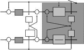
UPFC (Série)
The re fere nce powe r a nd reac tive P * a nd Q * of the des ire d rea l powe rs P a nd Q a re use d as input to the control sys te m of UPFC. From equa tion (8) the re fe rence currents isd*a nd isq * ca n be ca lcula te d as follows . The refe re nce curre nts I rdref I rqref a nd are ca lcula te d according to equa tions (8). These re fe rence va lues a nd I rdref I rqref a re the n compa re d with actua l line curre nts from the
* -
sd
+ PI
vcd + +
- +
1 S+r/l
isd
re ce iver.
The outputs of the PI e ditors provide the curre nt va lue s of control voltages Vsd a nd Vcq. The goa l is to have a ctive a nd reactive powe r a t the finis h line (Rece iving End) ide ntica l to those ins tructions
(P *, Q *) by forcing the line curre nts (I sd , I sq) to monitor properly
*
isq +
+ +
-
PI + +
vcq
1
S+r/l
isq
the ir refe re nces . The re fere nce curre nts ca lcula te d (8) compa re d to the actua l line curre nts a nd a fte r a correction to the curre nt one e nds control volta ges (UPFC se ries ) a nd V cd Vcq re prese nting the re fe re nce voltage control circuit (PW M) of the inve rter in Fig. 3.
According to the s ys tem of e qua tions (3) or (5), one ca n have the s ys tem conta ins a coupling be twee n the reactive and active curre nt Id Iq. The inte raction betwee n curre nt loops ca use d by the coupling term (ω) (Fig. 3). This e xpla ins the devia tion of reactive powe r with res pect to the re fere nce . To re duce the inte raction be twee n the active a nd reactive power, a decoupling of the two curre nt loops is nee de d.The function of decoupling is to remove the product ωL a nd I q controlle r a long the a xis d a nd a dding the product te rm ωL I d a nd the controller a long the a xis q. The des ign of the control s ys tem mus t be gin with the se lection of va ria bles to a djus t a nd the n tha t of the control varia bles a nd the ir associa tion with va riables se t. There is va rious a djus tment te chniques we ll s uite d to the PI controlle r. The re a re two we ll-known e mpirica l a pproaches propose d by Zie gle r a nd Tit for de termining the optima l pa ra mete rs of the PI controller. The method
Fig. 3 Block Diagram of the UPFC Control (series)
(a)
(b)
IJSER © 2 http:// www.ij
Inte rnatio nal Jo urnal o f Scie ntific & Eng ine e ring Rese arc h Vo lume 3, Issue 3, Marc h -2012 4
ISS N 2229-5518
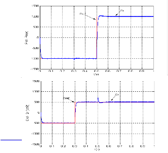
Fig. 4 (a), (b). Answ ers of Pow ers w ith PI-D.
Figures (4-a , b) illus tra tes the beha viour of a ctive a nd reactive powe r, whe re we see tha t the control s ys tem has a fa st dynamic re s ponse to the forces reach the ir s tea dy s ta tes a fter a cha nge in the re fe rence va lues .
We a ls o note the presence of the intera ction be twee n the
two compone nts (d a nd q). These influe nces a re ca use d by the PW M inve rter is una ble to produce continuous s igna ls nee de d by the decoupling, thus increas ing the e rror in the PI -D controlle rs .
To tes t robus tness , we teste d for a va riation of the reacta nce
XL to 30% a nd I ha d va ria tions on the output powe r following
Following the se cha nges , the a ctive a nd rea ctive powe r
(Fig. 5) unde rgo la rge devia tions more or less with a n ove rflow a t times of grea t cha nge ins tructions (Pre f, Qref), which mea ns the pe rforma nce de gra da tion of the PI controlle r, interpre te d by the loss of s ys tem s ta bility
We s imula te d this time by introducing perturba tion (Fig. 6)
dura tion of 25 ms a nd a mplitude 1.5 to tes t a ga in its robus tness
a nd s ta bility of the s ys tem.
The res ponse of active a nd rea ctive powe r at 30% of XI could
be de tecte d; the e rror messa ge give n by "MATLAB comma nd"
indica te d the sa tura tion of the orde r a t infinity in the s pike s of the re fe re nce s igna ls .
We ca n check the res ponse of the se rvo not only continue d but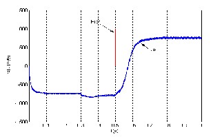
a lso regula tion by a dding a dis turba nce
Fig. 5 Answ ers Pow ers to Change the Reactance of 30%
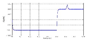
Fig.6. UPFC System Perturbed to Test Stability
The inte rest in a da ptive control [4] a ppea rs ma inly a t the le ve l of para me tric pe rturba tions , ie act on the cha racte ris tics of the process to be controlle d, dis turba nce a cting on the va riable s to control or order. I n this pa pe r we present the metho d of a djus tme nt propose d for the UPFC, e mphas izing the class ica l a pproach base d on ne ura l ne tworks .
I n this pa per the Elma n ne twork [5] s a id hidde n la yer ne twork is a recurre nt ne twork, a nd there fore be tter s uite d for mode lling dyna mic s ys tems . His choice in the ne ura l control by s ta te s pa ce is jus tifie d by the fact tha t, in pa rticular, the ne twork ca n be inte rpre te d as a s ta te s pa ce mode l nonlinea r. Lea rning by back propa ga tion a lgorithm s ta nda rd is the la w use d for the ide ntifica tion of the UPFC.
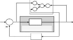
The inte gra tion of these two a pproaches (ne ura l a da ptive control) [6] in a s ingle hybrid structure, tha t each be nefits from
the othe r, but to cha nge the dyna mic be ha viour of the UPFC
s ys tem was a dde d a ga ins t a reaction ca lcula te d from the s ta te vector (s ta te s pace ) (Fig. 7).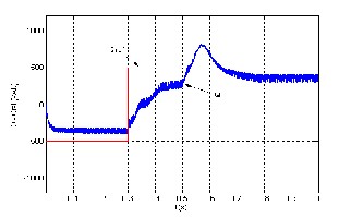
![]()
E (t) +
IJSER © 2012 http :// www.ijser.org
U (t)
Process’s
UPFC

Y (t)
Inte rnatio nal Jo urnal o f Scie ntific & Eng ine e ring Rese arc h Vo lume 3, Issue 3, Marc h -2012 5
![]()
![]()
![]()
ISS N 2229-5518

K x (t)
Fig. 7 Block Diagram of Feedback Control State of the UPFC.
The s ta te fee dba ck control is to cons ide r the process mode l in the form of a n e qua tion of s ta te ![]() :
:
X٭ (t) = A x (t) + B u (t) (11)
And observa tion e qua tion:
Y (t) = C x (t) +D u (t) (12)
W here u(t) is the control vector, x (t) the s ta te vector, a nd y (t) the output vector of dime ns ion for a dis cre te syste m to the sa mpling process pa rame ters Te a t times of Te sa mple k a re forma lize d a s follows :
x(t+1) = Ad x(t) + B ud(t) (14)
hidde n la ye r a nd output la ye r. The laye rs of input a nd output inte rfere with the e xterna l e nvironme nt, which is not the case for the interme dia te la ye r ca lle d hidde n la ye r ie the network input is the comma nd U (t) a nd its output is Y (t).
The s ta te vector X (t) from the hidde n laye r is inje cte d into the input la ye r.
We de duce the following e qua tions :
X (t) = W r X (t-1) + W h U (t-1) ( 21) Y(t) = W o X (t) (22)
W here , W h ; W r e t Wo a re the we ight ma trices . Equa tions a re
s ta nda rd de scriptions of the s ta te s pace of dyna mica l s ys tems .
The orde r of the sys te m de pe nds on the number of s ta tes e qua ls
the numbe r of hidde n laye rs . W he n a n input-output da ta is
prese nte d to the network a t ite ra tion k s qua re d error a t the output
of the ne twork is de fine d as
Y(t) = Cd x(t) + Dd u(t) (15)
E t
![]()
1 y (t) y(t)2
2
(23)
The tra ns fer function G (s ) = Y (s ) / U (s ) of our process UPFC ca n
For a ll da ta u (t), yd (t) de t = 1,2,….. N, the s um of square d e rrors
N
be writte n as :
is :
E E t
t 1
(24)![]()
Gs 1
(16)![]()
The we ights a re modifie d a t each ite ra tion, for W 0 we have :
s r L
E t
![]()
W0
![]()
y (t) y(t)y(t)
d W
(25)
We de duce the e qua tions of sta te re presenta tion of the UPFC:
y (t)
y(t).x T (t)
r
![]()
x* .
L
(17)
d
![]()
For W h e t Wr, we re : E t
E
![]()
t
![]()
![]()
. y(t) . x(t)
y x
Wh
y(t) x(t)
Wh
y (t) y(t).WT .u(t)
(26)
W ith: U (t)=e (t) –k x (t)
Le t: X (t +1) = [Ad – K B d] x (t) + B d e (t) (18)![]()
E t
d
E
![]()
t
0
![]()
![]()
. y(t) . x i (t)
Y (t) = Cd x (t) (19)
W i
y(t) x i (t)
W i
![]()
y (t) y(t).W i x i (t)
(27)
The dyna mics of the process correcte d by s ta te s pa ce is prese nte d base d on the cha racte ris tic e qua tion of the ma trix [Ad - Bd K],
d
x i T
0 W i
i x(t 1)
whe re K is the ma trix s ta te s pace controlle d process .
Our sys te m is des cribe d in ma trix form in the s ta te s pace :
The la tter we obta in:![]()
X (t 1) W .
W i r
![]()
W i
(28)
x * A.x B.u
(20)
The va ria tion of the we ight ma trix base d on the lea rning ga in is
y C.x D.u
![]()
writte n as : W . E t
W
Elman net work
(29)
W here :
r
![]()
L A
r
L
1
![]()
L B
0
1
L
1
C
0
0
1
0
D
0
0
0
W0 , W h et Wr
v cd
i sd
u
y
x i
i sq
e (t)= i* +
G(s)
V(t)= id
cq sq
u(t)=Vc
UP FC in system the state
space
Process ide ntifie d [7] [8] will be cha racte rize d by the mode l s tructure (Fig. 8), of his orde r a nd pa ra mete r va lue s . I t is there fore , a corolla ry of the s imula tion process for which us ing a mode l a nd a set of coe fficie nts to pre dict the res ponse of the
s ys tem. The Elma n network cons is ts of three la ye rs : a n input la yer,
K
Est imat ed st at e vector
X
Fig. 8 Netw ork EL MAN and State Space.
Note tha t the performa nce of the ide ntifica tion is bette r whe n the input s igna l is s ufficie ntly high in freque ncy to e xcite the differe nt
IJSER © 2012 http :// www.ijser.org
Inte rnatio nal Jo urnal o f Scie ntific & Eng ine e ring Rese arc h Vo lume 3, Issue 3, Marc h -2012 6
ISS N 2229-5518
modes of process . The three we ights Wo, W r a nd W h which a re re s pective ly the ma trices of the equation of s ta te of the process
s ys tem (UPFC) [CA a nd B] beca me sta ble a fte r a rough time
t = 0.3s a nd se vera l ite ra tions (fig. 9).
Note: For the Elma n network ne uron type is ass ume d through the vector is zero (D = 0).
I n online lea rning Elma n ne twork, the tas k of ide ntifying
a nd correcting same s ynthes is a re one a fte r the other. Or correction of the numerica l va lues of the pa rame ters is done re pea te dly s o the estima tion error (Fig. 10) ta ke s a bout a lmos t a second (t = 1s ) to conve rge to zero ie re gulation in purs uit.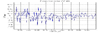
Fig. 9 Changing We ight
Fig. 10 Estimat ion Error
To check the robus tness to the controller, two tes ts were pe rforme d. For each tes t we va rie d the pa rame te rs of the tra nsmiss ion line but the controller rema ins uncha nge d. I t ca n be see n tha t the va ria tion of the reacta nce (± 25%) has a lmos t no influe nce on the output cha racte ris tics of the UPFC sys te m (Fig.
11).To compa re the res ponses of a ctive a nd reactive powe r of UPFC sys te m, we ga ve the three cases (Fig. 11) W here (a ) a nd (c) a re the res ponses to cha nges (± 25%) a nd (b) is the res ponse of the s ys tem without a ny cha nge in reacta nce .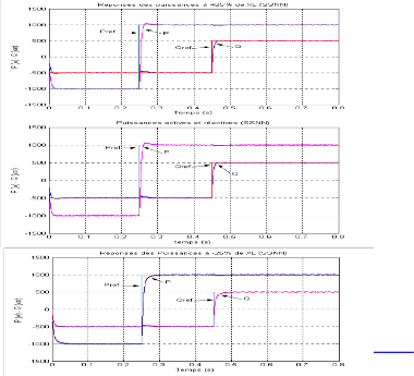
(a )
(b)
(c)
Fig. 11 Neural Adaptive Control (SSNN) Pow ers P, Q And at (± 25% XL)
6 Conclu sio n
The ide ntifica tion process will be cha racterize d by the mode l s tructure , its orde r a nd pa ra mete r va lues . I t is the re fore a corolla ry of the s imula tion process which uses a mode l a nd a set of coe fficie nts to pre dict the res ponse o f the syste m. The use of more a dva nce d low-ide ntifica tion ne ura l ne twork ca n be de pe nda ble in the ca lcula tion a lgorithm of the orde r.
I n this pa pe r we use d for the ide ntifica tion of s ys tem pa ra mete rs a ne uron ne twork sa id Elma n ne twork with thre e la ye rs . As we ha ve a lrea dy see n. Note tha t the performa nce of the ide ntifica tion is be tte r whe n the input s igna l is s ufficie ntly high in fre que ncy to e xcite the diffe re nt modes of process .
Ne ura l a da ptive control by sta te fee dbac k (SSNN: s tate s pa ce ne ura l ne twork)) is a hybrid control base d on the re prese nta tion of s ys tem s ta tus UPFC was teste d. The pe rforma nce of the la tter are s lightly de gra de d, this is ma y be due to the de la y ca use d by the a lgorithm, it can't be re duce d a t wil l, or it ma y due to the choice of the ga in K of the close d loop.
Fina lly, the ide ntifica tion process base d on lea rning of Elma n ne ura l ne twork, provide s the dyna mic be havior of the process a nd to es tima te the syste m output as its s ta te vector base d on the informa tion tha t a re control s igna l a nd the meas ure d output.
7 References
[1] I. Papic , P. Zunko , D. Pov h, M. We inho ld, ‚Basic contro l o f unifie d
po we r flo w co ntro lle r‛. IEEE Tra ns. Power Syst., vo l. 12, no. 4, pp.
1734–1739, 1997.
[2] Y. H. so ng and A .T. Jo hns,’ fle xible AC transmissio n sy ste ms
(FACTS).’ IEE po we r and Ene rgy se rie s 30.1999.
[3] Gy ugy i L.: unifie d po we r flow co ntro l conce pt fo r fle xible AC
transmissio n syste ms. IEE Proc. 139 (1992) 323 -331
[4] O. page s ‘é tude de co mparaiso n de diffé re nte s struc tures de co mmande multi - co ntrô le urs applic atio n à un axe ro bo tise.’ thèse
2001. (LAMII/CESALP).unive rsité de S avo ie .
[5] Xiang Li, Guanro ng C., Ze ng qian C., and Z. Yuan ‘Chao tify ing
Line ar Elman Ne two rks’ IEEE transac tio n ne ural ne two rks. vo1, 3. 5
Se pte mbe r 2002.
[6] M. A. De naï, T. Allao ui, ‚Adaptiv e fuzzy Deco upling o f UPFC -
Po we r Flo w Co mpe nsatio n‛, 37th UPEC2002, 9 -11 Se pte mbe r 2002,
S traffo rdshire s Unive rsity UK.
[7] S. ze birate , A.c hake r,O.traiaia , ‘co mmande addaptativ e
deco uple ne uro nale d’un co mpe nsate ur de flux de puissance
UPFC’re fe re nce480.labo rato ire LAAS.CCECE 03 -CCGEI
2003.Mo ntre al.IEEE May 2003.
© 2012 w.ijser.org
International Journal of Scientific & Ergireerirg Research Volume 3, Issue 3, March -2012 7
lSSN 2229-5518
[8] S. zebirate, A.chaker, 'commande addaptative decouple reuronale d'un UPFC (unified power flow control)', JCGE Saint Nazaire,Juin
2003.
1 --GER IS)2012
rttp://W\W/.1! ser.crg