International Journal of Scientific & Engineering Research, Volume 2, Issue 3, March-2011 1
ISSN 2229-5518
Near State PWM Algorithm with Reduced Switching Frequency and Reduced Common Mode Voltage Variations for Vector Controlled Induction Motor Drive
K. Satyanarayana, J. Amarnath, A. Kailasa Rao
—————————— • ——————————
HE vector control methods are widely used for the control of induction motor drives in high- performance applications due to its advantages [1].
The vector control algorithm gives a decoupling control between torque and flux so that the induction motor can be controlled as a separately excited dc motor. However, the classical vector control algorithm uses hysteresis con- trollers for the generation of gating signals to the voltage source inverter (VSI), which results in variable switching frequency operation. To achieve constant switching fre- quency operation of the inverter, the space vector pulse width modulation (SVPWM) algorithm [2] has been used for vector controlled induction motor drive. Among the various possible PWM algorithms SVPWM gives superior performance and gives reduced harmonic distortion [3]. The SVPWM algorithm divides the zero voltage vector time equally among the two zero voltage vectors.
To reduce the harmonic distortion, the zero voltage space vectors are used in SVPWM algorithm, which results in large common-mode voltage (CMV) variations. The poor CMV characteristics lead to prohibitive amount of com- mon-mode current (CMC) in induction motors. In induc- tion motor drive applications, this may lead to motor bearing failures, electromagnetic interference (EMI) noise, or interference with other electronic equipment in the vicinity [4]-[5]. Such problems have increased recently due to increasing PWM frequencies and faster switching times. The filters can be utilized to suppress the effect of
the CMV from the source. However, these methods in-
cost [9]-[11]. A novel remote state PWM algorithm is pre- sented in [9] and a near state PWM (NSPWM) algorithm is presented in [10]. The detailed survey and analysis of various PWM algorithms has been carried out and proved that NSPWM algorithm gives superior perfor- mance when compared with the other PWM algorithms [11].
This paper presents space vector based NSPWM algo- rithm with reduced switching frequency for reduced CMV in vector controlled induction motor drives.
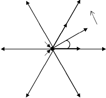
Voltage source inverters (VSI) are utilized in many appli- cations. The three-phase, two-level VSI has a simple struc- ture and generates a low-frequency output voltage with controllable amplitude and frequency by programming high-frequency gating pulses. For a 3-phase, two-level VSI, there are eight possible voltage vectors, which can be represented as shown in Fig. 1. Among these voltage vec- tors, V1 to V6 vectors are known as active voltage vectors or active states and the remaining two vectors are known as zero states or zero voltage vectors. The reference vol- tage space vector or sample, which is as shown in Fig. 1 represents the corresponding to the desired value of the fundamental components for the output phase voltages.
In the space vector approach this can be constructVed in an average sense. The reference voltage vector ( ref ) is
volve additional hardware, and thus, they significantly
sampled at equal intervals of time, Ts
referred to as sam-
increase the drive cost and complexity. An alternative approach is to modify the pulse pattern of the standard PWM algorithm such that the CMV is substantially re- duced from its source and its effects are mitigated at no
pling time period. Different voltage vectors that can be
produced by the inverter are applied over different time
durations with in a sampling time period such that the
average vector produced over the sampling time period is
IJSER © 2011
2 International Journal of Scientific & Engineering Research, Volume 2, Issue 3, March-2011
ISSN 2229-5518
equal to the sampled value of the ref , both in terms of magnitude and angle. It has been established that the vec-
are symmetrical, the discussion is limited to the first sector only. For the required reference voltage vector, the active
voltage vectors (V1, V2 and V6) times can be calculated as in
V3 (010)
II
V2 (110)
(4), (5) and (6).
= r- 1 + 3
![]()
cos(a + n ) + 3 3
sin(a + n ) 1
(4)
III
T2 Vref I
Motor![]()
T1 H
L
n M i
![]()
3 n M i
![]()
Ts
3 J
V (111)
r 3
T2 H1 M i
cos(a + n ) -
![]()
3 M sin(a + n ) 1
(5)
7 a V1 (100)
![]()
![]()
L n 3 n
![]()
3 J
V4 (011)
V0 (000) T1
IV VI V
V5 (001) V6 (101)
d
T6 = Ts - T1 - T2
(6)
V3 (010) V2 (110)
II III
Fig. 1 Possible voltage space vectors and sector definition in
SVPW M algorithm
tors to be used to generate any sample are the zero vol- tage vectors and the two active voltage vectors forming the boundary of the sector in which the sample lies. As all six sectors are symmetrical, the discussion is limited to the first sector only.
V4 (011)
IV
V
I V1 (100)
VI
For the required reference voltage vector, the active and zero voltage vectors times can be calculated as in (1), (2) and (3).
V5 (001) V6 (101)
2 3
![]()
T1 = n
M i sin(60 o
- a )Ts
(1)
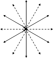
Fig. 2 Possible voltage space vectors and sector definition in
NSPW M algorithm
But, in the NSPWM algorithm, the (4), (5) and (6) have a![]()
T = 2 3 M
2 n i
sin(a )Ts
(2)
valid solution when the modulation index is varying be- tween 0.61 and 0.906 [10]. In order to get minimum
Tz = Ts - T1 - T2
(3)
switching frequency and reduced common mode voltage
the NSPWM algorithm uses 216-612 in sector-I, 321-123 in
sector-II and so on.
where M i
is the modulation index and defined as in [1].
The total number of commutations in SVPWM algorithm
In the SVPWM algorithm, the total zero voltage vector
time is equally divided between V0 and V7 and distri- buted symmetrically at the start and end of the each sam-
pling time period. Thus, SVPWM uses 0127-7210 in sec- tor-I, 0327-7230 in sector-II and so on.
The near state PWM (NSPWM) algorithm uses a group of three neighbor voltage vectors to construct the reference vol- tage vector. In order to reduce the common mode voltage variations, the proposed NSPWM algorithm did not use the zero voltage vectors. These three voltage vectors are selected such that the voltage vector closest to reference voltage vec- tor and its two neighbors are utilized in each sector. Hence, the utilized voltage vectors are changed in every sector. As shown in Fig. 2, to apply the method, the voltage vector space is divided into six sectors. Here also, as all six sectors
is three in a sampling time interval, where as the number of commutations in NSPWM algorithm is two. Moreover, the modulating waveform of NSPWM algorithm is simi- lar to the DPWM1 waveform and hence any one of the phases is clamped to the positive or negative DC bus for utmost a total of 1200 over a fundamental cycle. Hence, the switching losses of the associated inverter leg are eliminated. Hence, the switching frequency of the NSPWM algorithms is reduced by 33% compared with SVPWM algorithm.
In the vector controlled induction motor drive, a VSI is
IJSER © 2011
International Journal of Scientific & Engineering Research, Volume 2, Issue 3, March-2011 3
ISSN 2229-5518
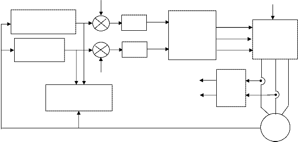
supposed to drive the induction motor so that the slip fre- quency can be changed according to the particular require- ment. Assuming the rotor speed is measured, and then the slip speed is derived in the feed-forward manner. The block diagram of proposed vector controlled induction motor drive is as shown in Fig. 3. This shows how the rotor flux linkage position can be obtained by integrating the sum of rotor
speed and actual speed. In the vector control scheme, to re-
ate the desired rotor flux linkage and rotor speed are not directly related to these variables. So the alternative way is to regulate the rotor flux linkage and rotor speed through PI controllers and the outputs of these two controllers give out the reference values for the q- and d-axis stator currents in synchronous reference frame. Then the actual q- and d-axis stator currents are regulated to these two reference currents
to get the stator voltages. Then these two-phase voltages are
gulate 'Ar
jectives.
and rotor speed to desired values are the two ob-
converted into three-phase voltages and given to the RPWM
block, which generates the gating pulses to the VSI.
ids
ror
Field weaken control *
Speed control- *
ler
V*ds
PI
PI
V*qs
NSPWM
Vdc
Sa
Sb 3-Phase VSI
Sc
iqs
Slip & Angle Calcula- tion
ids
iqs
3-ph to Ia
2-ph
ib
ror
IM
Fig. 3 block diagram of NSPW M based vector controlled I.M.drive
Apparently the stator voltages that are required to gener-
To validate the proposed NSPWM algorithm, the numerical simulation studies have been carried out using MATLAB. For the simulation studies, the average switching frequency of the inverter is taken as 5 kHz. In order to maintain the constant average switching frequency, the switching fre- quency of SVPWM algorithm is taken as 5 kHz and that of NSPWM algorithm is 7.5 kHz. The induction motor used in this case study is a 4 kW, 400V, 1470 rpm, 4-pole, 50 Hz, 3- phase induction motor having the following parameters: Rs=
1.570, Rr = 1.210, Ls = 0.17H, Lr = 0.17H, Lm = 0.165 H and J =
0.089 Kg.m2.
The simulation results of SVPWM algorithm based vector controlled induction motor drive are shown in Fig.4-Fig. 7.
Fig. 4 Steady state plots of SVPW M algorithm based vector con- trolled induction motor drive
IJSER © 2011
4 International Journal of Scientific & Engineering Research, Volume 2, Issue 3, March-2011
ISSN 2229-5518
Fig. 5 Harmonic spectra of line current in SVPW M based vector controlled induction motor drive
Fig. 8 Steady state plots of NSPW M algorithm based vector con- trolled induction motor drive
Fig. 6 Line voltage waveform of SVPW M algorithm based vector controlled induction motor drive
Fig. 9 Harmonic spectra of line current in NSPW M algorithm based vector controlled induction motor drive
Fig. 7 Common mode voltage variations in SVPW M algorithm based vector controlled induction motor drive
Fig.4 shows the steady state plots of vector controlled induc- tion motor drive. Fig. 5 shows the harmonic spectra of line current along wth the THD value.Fig. 6 shows the line vol- tage waveform of SVPWM algorithm based vector controlled induction motor drive in steady state and Fig. 7 shows the common mode voltage variations with the SVPWM algo- rithm, from which it can be observed that the common mode voltage is varying between +0.5Vdc and -0.5Vdc. the simula- tion results of NSPWM algorithm based drive are shown from Fig. 8 to Fig. 11.
Fig. 10 Line voltagewaveform of NSPW M algorithm based vector controlled induction motor drive
IJSER © 2011
International Journal of Scientific & Engineering Research, Volume 2, Issue 3, March-2011 5
ISSN 2229-5518
Fig. 11 Common mode voltage variations in NSPW M algorithm based vector controlled induction motor
From Fig. 5 and Fig. 9, it can be observed that the NSPWM algorithm gives more THD when compared with the SVPWm algorithm. Moreover, from Fig. 7 and Fig. 11, it can be observed that the NSPWM algorithm gives less common mode voltage variations when compared with the SVPWM algorithm.
Thus, from the simulation results, it can be observed that the proposed NSPWM algorithm reduces common mode voltage when compared with the SVPWM algorithm with slight increase in harmonic distortion. Moreover, from the line voltage waveforms, it can be observed that there are opposite pulses in line voltage of NSPWM algorithm. Also, as the proposed algorithm clams any one of the phases for a total period of 120 degrees over a fundamental cycle, it re- duces the switching losses of the inverter and also the switching frequency of the inverter is 2/3 times to that of the SVPWM algorithm.
In this paper, a NSPWM algorithm is presented for vector controlled induction motor drives. to validate the pro- posed algorithm, simulation studies have been carried out and results are presented. From the results, it can be observed that the proposed NSPWM algorithm gives less common mode voltage variations when compared with the SVPWM algorithm with slight increase in harmonic distortion. Also, as the proposed NSPWM algorithm is a bus-clamping sequence, it reduces the switching losses by
33.33%. Hence, the switching frequency of the proposed NSPWM algorihm is also less when compared with the SVPWM algorithm.
[1] F. Blaschke “The principle of field orientation as applied to the new transvector closed loop control system for rotating-field machines," Siemens Review, 1972, pp 217-220.
[2] Heinz Willi Vander Broeck, Hnas-Christoph Skudelny and
Georg Viktor Stanke, “Analysis and realization of a pulsewidth
modulator based on voltage space vectors” IEEE Trans. Ind. Ap- plicat., vol. 24, no. 1, Jan/Feb 1988, pp. 142-150.
[3] Joachim Holtz, “Pulsewidth modulation – A survey” IEEE Trans. Ind. Electron.., vol. 39, no. 5, Dec 1992, pp. 410-420.
[4] J.M. Erdman, R. J. Kerkman, D.W. Schlegel, and G. L. Skibinski, “Effect ofPWMinverters onACmotor bearing currents and shaft voltages,” IEEE Trans. Ind. Appl., vol. 32, no. 2, pp. 250–259, Mar./Apr. 1996.
[5] G. L. Skibinski, R. J. Kerkman, and D. Schlegel, “EMI emissions
of modern PWM AC drives,” IEEE Ind. Appl. Soc. Mag., vol. 5, no. 6, pp. 47–81, Nov./Dec. 1999.
[6] Y. S. Lai and F. S. Shyu, “Optimal common-mode voltage re- duction PWM technique for inverter control with consideration of the dead-time effects—Part I: Basic development,” IEEE Trans. Ind. Appl., vol. 40, no. 6, pp. 1605–1612, Nov./Dec. 2004.
[7] Y. S. Lai, P. S. Chen,H.K. Lee, and J.Chou, “Optimal common-
mode voltage reduction PWM technique for inverter control with consideration of the dead-time effects—Part II: Applica- tions to IM drives with diode front end,” IEEE Trans. Ind. Appl., vol. 40, no. 6, pp. 1613–1620, Nov./Dec. 2004.
[8] J. Zitzelberger andW. Hofmann, “Reduction of bearing currents
in inverter fed drive applications by using sequentially posi- tioned pulse modulation,” EPE J., vol. 14, no. 4, pp. 19–25, 2004.
[9] M. Cacciato, A. Consoli, G. Scarcella, and A. Testa, “Reduction of common mode currents in PWM inverter motor drives” IEEE Trans. Ind. Applic. Vol.35, no.2, pp. 469-476, Mar/Apr, 1999.
[10] Emre Ün and A.M. Hava, “A near state PWM method with
reduced switching frequency and reduced common mode vol-
tage for three phase voltage source inverters” IEEE-IEMDC, pp.
235-240, May, 2007.
[11] A.M. Hava, and Emre Ün, “Performance Analysis of Reduced Common-Mode Voltage PWM Methods and Comparison with Standard PWM Methods for Three-Phase Voltage-Source Inver- ters” IEEE Trans. Power Electron., vol.24, no.1, pp. 241-252, Jan,
2009.
IJSER © 2011