International Journal of Scientific & Engineering Research, Volume 5, Issue 5, May-2014 1
ISSN 2229-5518
Modelling Analysis and Realization of a
Supporting System for Afflicted Subjects
Jobin Varghese, T.S.Sirish, K.S.Sivanandan, P.K.Rajendrakumar
Abstract: W alking assistive devices have wide range of demand through out the year all around the globe. A simple linear mathematical model connecting input output relationship for both angular displacement and knee moment has been derived. Derived mathematical model for knee moment has been compared with the knee moments obtained from newton’s equations of motion. The results obtained is validated by comparing with the fabricated structure results.
Keywords: Average value based,moment,Primary sector, Secondary sector ,Tertiary sector, W alking assistive device
1. INTRODUCTION
—————————— ——————————
Locomotion have prior importance for any human beings in their life. Hence walking assistive devices are always a boon for the afflicted human beings. At present, variety of walking devices are widely available for different gait irregularities. But the most preferred one is selected depending on the suitable gait characteristics of a subject that it can exhibit. The present walking assistive devices which are more popular and widely available in markets viz., HAL-Hybrid Assistive Limb, exoskeleton, have more focus on the suitability of gait characteristics. Further improvements can be made on walking asstive devices if and only if a perfect gait analysis is carried out and new methods are implemented. A robot suit HAL (hybrid assistive limb) [1] has been developed by T Hayashi et.al, as an walking assistive device for lower limbs. Here the assistive device will develop torque corresponding to myoelectricity signal which has biological information to produce muscle contraction for required torque. BLEEX [2] demonstrated first energetically autonomous, seven degrees of freedom, hydraulically actuated walking assistive device that can carry the payload. A wearable walking helper has been proposed by [3] Takahiko et. al, whose function is to support below hip antigravity muscles. Here the required knee moment for a specific model is calculated based on the antigravity term of necessary knee moment.
An assistive device, which can reduce or eliminate the effects of gravity, for persons with hemi paresis to walk was proposed by [4] Sai et. al,. Jerry E Pratt et.al [5] developed a Rob knee which can be worn on the knee and can be used to climb stairs and in
acute knee bends during payloads.
This has one degree of freedom and requirement of torque that has to be developed at knee is sensed by knee joint angle and ground reaction forces. knee ankle foot orthosis (KAFO) supports the lower limb and enable Partially or fully paralysed people to regain their locomotion.Kenton et.al [6] [7-9] proposed an improved KAFO for an articulated knee joint system that reduces the metabolic energy expenditure during walking. This KAFO improves the knee stability during stance phase by locking the knee and unlocks the knee during swing phase of the gait cycle.
The development of an efficient KAFO relies on the research in biomechanics of gait cycle. Biomechanics of gait cycle deals with forces and moments [10] [11] especially, forces and loading at the foot [12] [13] and at the hip [14] [15]. Ground reaction forces and positional co-ordinates are measured and located using markers and force plates [16]. Inverse dynamics models are used to determine the force and moments at different joints using ground reaction forces [17] [18]. Angles and positional co-ordinates are used to determine velocity and acceleration using forward dynamic models [19] [20] [21] .
Even though many vast developments in KAFO has been cited in literature, a general, mathematical models of a system which can assist for the smooth and easy function of a handicapped (afflicted human locomotion) is not specifically seen This work focus on the comparison of two methods: 1)Newton’s equations of motion 2) Average value based method.
2. 2Average value based model development
Gait cycle of a normal male subject is recorded using a high resolution,40 frames per second, camera. The gait cycle is recorded for every 25 milli seconds interval. Here the main focus of gait cycle recording is for observing angular displacement of knee joint. knee joint angular displacement is recorded for a time
2.1. 2 Linear Mathematical Model
period of T
to T
seconds. From the tabulated reading it was
R i R
RfR
observed that the angular displacement varies with time, which
IJSER © 2014 http://www.ijser.org
International Journal of Scientific & Engineering Research, Volume 5, Issue 5, May-2014 2
ISSN 2229-5518
represents the dynamic state of the subject. This enhances the requirement for developing a linear mathematical model for the
dynamics state. Mathematical model is developed using a method similar to finite difference method. For this the total time frame has to be divided into certain sectors viz., primary, secondary, tertiary sectors.
The recorded knee angular displacement are divided into certain sectors depending on the equality of the average values. For a general division of sectors, time frame can be used as reference. The number of sectors with same average values are grouped under the category primary sectors and corresponding average values of these sectors are named as primary averages. Primary sectors are further
categorised into secondary sectors which have average value
which are slightly different from the average value of primary sectors.The average value of this sectors are so called first variational term. Similarly secondary sectors are further categorised into teritiary sectors which have average values which are slightly different from the average values of primary sectors.The average value of this sectors are so called second variational term
An input output relationship has to be created using the categorized sectors for further study of the dynamics of the system. Assuming the system to be linear the following input output relation ship is assumed. The output is a function of base average value, first variational change from base average value, second variational change from first variational term and so on. Base average value is the average of difference between primary sector average and total average. Similarly first variational term is the average of difference between primary sector average and secondary sector average. The variational terms has to be multiplied by the some factors N1, N2, N3 to make the relation linear. The input output is represented as
Input=N1 (Base average) +N2 (First variational term)+N3 (Second variational term)+ ………….
The input part should also be considered as a summation terms involving base average value and variational terms. But to avoid practical complexity, it is considered as only one term.
2.2. Procedure for Finding the Variational Parts:
To calculate first variational term :
a. Split the whole data into feasible number of of primary sectors and calculate its average.
b. Primary sector is again splitted into feasible number of secondary sectors and calculate its average
c. Difference between primary averages and secondary
averages is computed.
d. The average of the difference between primary and
secondary sector averages is the first variational term.
To Calculate second variational term:
a. Secondary sectors obtained above are splitted into feasible number of tertiary sectors.
b. Calculate the average of tertiary sectors.
c. Difference between the secondary averages and tertiary
averages has been computed
d. The average of the difference between secondary and
tertiary sector averages is the second variational term.
2.3. Inferences of Human Locomotion Positional
Analysis
Knee angle is found to be 550 during slow walking mode, 480 during normal walking mode and 350 in the fast walking. The hip angles are 250 for slow walking, 200 for normal walking and 150 for slow walking.The directions of angular velocity of hip and knee are opposite. The angular displacement, angular velocity and angular acceleration are measured and corresponding motion in walking assistive devices are obtained by supplying equivalent amout of current to moors through driving circuit. However some trial and error methods are adopted for making the characteristics similar to that of the given model.
3. Modeling Approaches
3.1. Kinematic and kinetic analysis using newtons equations of motion
A human gait cycle has three phases namely heel contact, midstance and propulsive phases (fig. 1). Heel
contact, Midstance and Propulsive phases constitutes 27%, 40%,
33% respectively of the gait cycle. During hell contact and toe
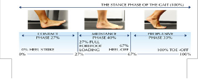
off phases, ground reaction forces are acting at foot as per newtons second law of motion. This ground reaction forces cause reaction forces and moments at the ankle, knee and hip joints. Moments and forces at the joints has to be determined for the design and development of the orthosis. Here newtons equation of motion for dynamic state is used for calculing the moments and forces acting at the joints.
Fig 1 Three Phases of gait cycle
Reaction forces and moments are calculated for a male subject with weight 80kg and height 6 feet. Length and mass of the leg segments are calculated using anthropometric ratio obtained from winter 1990. Reaction forces at the heel and toe region are measured from force plates that are installed in gait labs, where high resolution cameras are installed to capture the
IJSER © 2014 http://www.ijser.org
International Journal of Scientific & Engineering Research, Volume 5, Issue 5, May-2014 3
ISSN 2229-5518
Table 1 Calculation of moment and reaction force for 2nd 3rd and 4th frames
Frame | Time (sec) | mleg (kg) | aCOMX (m/s2) | aCOMY (m/s2) | RXleg (N) | RYleg (N) | r leg (mm4) | α2 (rad/sec2) | L 2 (m) | ɵ2 (deg) | M2 (N-m) |
2 | 0.014 | 3.72 | 7.99 | 0.37 | -0.8156 | 15.597 | 0.1359 | -46.59 | 0.45 | 38 | 7.568 |
3 | 0.029 | 3.72 | 4.97 | -0.29 | 7.16 | 8.55 | 0.1359 | -65.29 | 0.45 | 37 | 3.744 |
4 | 0.043 | 3.72 | 2.66 | -1.25 | 11.82 | 2.24 | 0.1359 | -77.66 | 0.45 | 36.7 | 3.82 |
𝐼. 𝛼
𝑎𝑥1
𝑎𝑦1
𝑅𝑦1
𝑅𝑥1
𝑀2
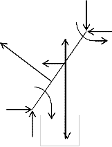
FX is the reaction force acting along x direction, F Y is the reaction force acting along y direction, ax is the acceleration acting in x direction, a y is the acceleration acting in y direction, m is the mass of the leg, M com is the moment about centre of gravity I is the moment of inertia and α is the angular acceleration of the leg.
𝑅𝑥1
𝑅𝑦1
𝑀1
𝑚. 𝑔
A mathematical input ouput relation is obtained using the base average value method. The moment at the knee is equated to product of moment of inertia and angular acceleration. The equations obtained are
4.028N1 + 4.835N2 + 0.78N3 = 2.38 (2)
Fig 2 Resolved forces and moments on a left leg segment during swing
phase
human locomotion. Markers are placed on different places on
the body for recording x and y position of the segment relative to a reference frame.This x and y co ordinates are fitted using curve fitting method in mat lab and obtain a quadratic, cubic or polynomial.
The resolved forces and moments acting on a right leg segment during swing phase is shown in fig.2.
Newton’s equations of motions for dynamic state is

(𝛴𝛴𝑥 )𝑖 = 𝑚𝑖 𝑎𝑥𝑖 R
5.044N1 + 11.901N2 + 7.487N3 = 1.28 (3)
5.014N1 + 7.142N2 + 2.93N3 = 0.66 (4)
The values N1 , N2 , N3 are obtained by solving above equations using matlab.This values corresponds to moment at a particular positional data.
4. Experimental Determination (Normal Walking)
An assistive device is fabricated using aluminium material (fig 3). High torque electric motors are assembled at thigh and angle joints. A locking mechanism using electrical dc motors and rack and pinion arrangement is assembled at knee joint. The function of locking mechanism is to lock the knee during locomotion so as to resist the bending of the knee while it is unlocked during sitting position or at situations where bending of the knee is required. A set of 600 angular displacement values has been recorded using camera and locking and
�𝛴𝛴 �
𝑖
= 𝑚𝑖 𝑎𝑦𝑖 R 𝑖 = 1,2,3 (1)
unlocking time for knee joint are tabulated. The tabulated values are fed as input to the average value based model and the base
(𝛴𝑀𝐶𝑂𝑀 )𝑖 = 𝐼𝑖 𝛼𝑖
average, first change in base average and second change in base average is calculated and are summarized in the Table 2.
IJSER © 2014 http://www.ijser.org
International Journal of Scientific & Engineering Research, Volume 5, Issue 5, May-2014 4
ISSN 2229-5518
2Table 22 Calculation of base average, first variational term and second variational term for knee angular displacement using Average value based method.
Primary Sector | A Angular displacements corresponding to frame no 1 to 200 | B Angular displacements corresponding to frame no 201 to 400 | C Angular displacements corresponding to frame no 401 to 600 |
Primary Sector | Knee | Knee | Knee |
Base Average Value for Right leg corresponding to angular displacement | 167 | 170 | 168 |
First Variational Term for right leg corresponding to angular velocity | 3.73 | 5.10 | 3.244 |
Second Variational Term for right leg corresponding to angular acceleration | 12.9 | 11.188 | 13.204 |
Locking time corresponding to right leg | 900 milli seconds |
Unlocking time corresponding to right leg | 425 milli seconds |
Time between locking and unlocking | 0.35 seconds |
IJSER © 2014 http://www.ijser.org
International Journal of Scientific & Engineering Research, Volume 5, Issue 5, May-2014 5
ISSN 2229-5518
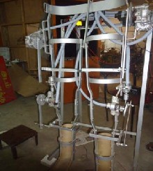
2 Fig 32 Walking assistive device
The following three equations are formulated using the data
Here the relation between a dependent variable and
collected in Table-2
167P1 + 3.73P 2 + 12.9 P3 = 3.6 (6)
170P 1 + 5.1P 2 + 11.18888P3 = 3.6 (7)
168P 1 + 3.244 P2 + 13.204P 3 = 3.6 (8)
independent variable is not accurately available from theory. The
optimum form of relation and the ‘best ‘ set of numerical
coefficients, given a set of measured data is found using MATLAB. The values of the constants are obtained by solving the above equations. For the subject consider for experimentation we obtain the values of P1,P2,P3.
5. Formulation of Mathematical Equations
The tabulated knee angular displacement values are divided into three primary sectors viz., sector A, sector B and sector C. These primary sectors are then subdivided into secondary and tertiary sectors. Average value based method is applied to each sector and three equations are formulated using following approach
P1 *(BavgA )+P 2 *(∆BvgA )+P 3*(∆2BavgA ) = distance covered corresponding to Primary Sector A
The constants P1, P 2 and P3 represents the physical parameters of the system, (∆BvgA ) is the first variational change that corresponds to secondary sector, ∆2Bavg A is the second variational change corresponds to tertiary sector.Simillarly for
Primary Sectors B and C
P1*(BavgB )+P2*(∆BvgB )+P3*(∆2BavgB ) = distance covered corresponding to Primary Sector B
P1*(BavgC )+P2*(∆Bvg C )+P3*(∆2BavgC ) = distance covered corresponding to Primary Sector C
Thus the general equation for the characteristics of human movement can be formulated as
P1*(Base AvgX ) + P2*(First change in Base AvgX )+P3*(Second change in Base AvgX ) = distance covered in Primary Sector X (5)
The normal walking video is captured for a finite time i.e. 20 seconds. The entire data base is divided into three Primary Sectors of 5 seconds each as explained above. The proposed method is applied, base value and variational terms are obtained for each Primary Sector as shown in Table-2. The entire distance covered in 20 seconds is 14.4 Meters and for each Primary Sector of duration 5 seconds the distance covered is
3.6Meters.
To make the cummulative angular displacement of the human locomotion smooth a Newton’s forward difference interpolation technique or Newton Gregory Formulae is used to approximate a given function, whose values are known at N+1 tabular point, by a suitable polynomial P N (x) of degree N which takes the values yi at x=xi for i=0,1,2,……. This enables us to find the intermediate values.
6. Analysis and Discussion
Model for knee moment and angular displacement are
developed using average value based method. By changing the
values of N1 , N2 and N3 in eqn (1),(2),(3), different values of moments at diffrent angles can be obtained for the dynamic state. Similarly by changing the values of P 1 , P2 , P3 in eqns (6),
IJSER © 2014 http://www.ijser.org
International Journal of Scientific & Engineering Research, Volume 5, Issue 5, May-2014 6
ISSN 2229-5518
(7) and (8) different values linear displacement is obtained for different angles of motion. By combining the equations, moment
and angular displacement for different angles are obtained. The two models shows a positive relation ship to the average value based problem. The present walking assistive device with electrical actuaction is bulky in size and weight. Since the dc motors are running on battery charge the size of the battery is a major concern for long distance locomotion with assistive device. Power source is always a major issue in any automated mechanism. Current and voltage are the other issues that affect the selection and maintenace of the power sources. Considering these factors, a different mechanism with low cost and widely available power source has to be selected for orthosis development. Here it is suggested that a pneumatic system is installed for the actuation purposes where the working fluid is the compressed air which is widely available.
7. Conclusion
High resolution camera was used to record the gait cycle positions and the angular displacement, angular velocities and angular accelerations has been measured and calculated. Using the data collected from the recorded video, an infinite series linear mathematical model has been developed and validated successfully. Forces and moments are calculated using newtons equations of motion. Knee moment is also calculated using average value based method and both methods show the similarity in results.
Practical realisation of the model developed has been performed by fabricating simple and cheap walking assistive device and its control techniques. The assistive device developed is simple, cheap and robust. Walking experiment is performed using fabricated walking assistive device and the gait movement were recorded using camera. The analysis reuslts shows that a good match between natural human gait cycle and gait cycle with walking assistive device.
References
[1]. T Hayashi,H Kawamoto and Y Sankai “ Control Method of Robot Suit HAL working as operator’s Muscle using Biological and Dynamical Information” IEEE /RSJ International conference on Intelligent Robots and Systems 2005.
[2]. Adam Zoss, H. Kazerooni, Andrew Chu “On the Mechanical Design of the Berkeley Lower Extremity Exoskeleton (BLEEX)” 2005 IEEE/RSJ International Conference on Intelligent Robots and Systems.
[3]. Takahiko Nakamura and Kazuhiro Kosuge “Model-based walking support system with Wearable Walking Helper” Proceedings of the
2003 IEEE International Workshop on Robot and
Human Interactive Communication Millbrae. Caliiomia. USA, Oct. 31 -Nov. 2.2003.
[4]. Sai K. Banala, Sunil K. Agrawal, Abbas Fattah “Gravity Balancing Leg Orthosis And Its Performance Evaluation”.
[5]. Jerry E. Pratt, Benjamin T. Krupp, Christopher J.
Morse and Steven H. Collins” The RoboKnee: An
Exoskeleton for Enhancing Strength and
Endurance during Walking” Proceedings of the
2004 IEEE, International Conference on Robotics
& Automation.
[6]. Kenton R. Kaufman, PHD,S.E. Irby, MS,J.W
Mathewson, MD,R.W. Wirta,D.H. Sutherland, MD “Energy- Efficient Knee-Ankle Foot Orthosis: A Case Study” jpo 1996.
[7]. Irby SE. A digital logic-controlled electromechanical free-knee brace, MS1 Thesis, San Diego State University, San Diego, Calif.,
1994.
[8]. Kaufman KR, Irby SE, Wirta RW, Us sell DW,
Mathewson JW, Sutherland DH. Knee-ankle-foot orthosis for free-knee gait. Second world congress of biomechanics. Amsterdam, The Netherlands, July 10-5, 1994:280.
[9]. Malcolm LL, Sutherland DH, Cooper L, Wyatt M.
A digital logic-controlled electromechanical
orthosis for free-knee gait in muscular dystrophic
children. Orthop Transactions 1980;5:90.
[10]. A.Seireg and R.J. Arvikar (1975) The prediction of
muscular load sharing and joint forces in the lower extremities during walking. Journal of Biomechanics, 8:89-102.
[11]. D. A. Winter(1990) Biomechanics and Motor Control of Human Movement, 2nded. Wiley, New York.
[12]. S. K. Au, P. Dilworth, and H. Herr (2006) An
ankle-foot emulation system for the study of
human walking biomechanics. IEEE Intl. Conf. on
Robotics and Automation, 2939-45.
[13]. M. M. Rodgers, “Dynamic biomechanics of the normal foot and ankle during walking and running,” Physical Therapy, vol. 68, no. 12, pp.1822-30, Dec. 1988.
[14]. G. Bergmann, F. Graichen, and A. Rohlmann
(1993) Hip joint loading during walking and running, measured in two patients. Journal of Biomechanics, 26:969-90.
[15]. M. O. Heller, G. Bergmann, G. Deuretzbacher, L.Durselen, M. Pohl, L. Claes, N. P. Haas, and G. N. Duda (2001) Musculo-skeletal loading conditions at the hip during walking and stair climbing. Journal of Biomechanics 34:883-93.
IJSER © 2014 http://www.ijser.org
International Journal of Scientific & Engineering Research, Volume 5, Issue 5, May-2014 7
ISSN 2229-5518
[16]. S. H. Scott and D. A. Winter (1993) Biomechanical model of human foot: Kinematics and kinetics during the stance phase of walking. Journal of Biomechanics 26:1091-104.
[17]. U. Glitsch and W. Baumann (1997) The Three
dimensional determination of internal loads in the lower extremity. ASME Journal of Biomech. Eng.,
30:1123-31.
[18]. S. Siegler and W. Liu(1997) Three-dimensional Analysis of Human Locomotion. In John Wiley & Sons (ed) Inverse Dynamics in Human Locomotion,1stedn. Wiley, pp.191-209.
[19]. F. C. Anderson and M. G. Pandy (2001) Dynamic optimization of human walking. ASME Journal of Biomech. Eng. 123:81-90.
[20]. R. R. Neptune, S. A. Kautz, and F. E. Zajac (2001) Contributions of the individual ankle plantar flexors to support, forward progression and swing initiation during walking. Journal of Biomechanics 34:1387-98.
[21]. M. G. Pandy and N. Berme (1988) A numerical method for simulating the dynamics of human walking. Journal of Biomechanics 21:1043-51.
Jobin varghese is currently pursuing doctoral degree in Biomechanics under mechanical engineering depatment in National Institute of Technlogy, Calicut, Kerala, India, PH- 9995103636
E-mail: jobinvargheset@gmail.com1
T.S. Sirish is currently pursuing doctoral degree in Biomechanics under electrical engineering department in National Institute of Technlogy, Calicut, Kerala, India, PH- 9037260927
E-mail: srinivassirish@nitc.ac.in
K S Sivanandan is currently working as the professor in electrical engineering department in National
Institute of Technology, Calicut, Kerala
E-mail: kss@nitc.ac.in
P K Rajendrakumar is currently working as the professor in Mechanical Engineering department in
National Institute of Technology, Calicut, Kerala
E-mail: pkrkumar@nitc.ac.in
IJSER © 2014 http://www.ijser.org