Modeling and Simulation of Technological
Parameters for Design and Optimization Blanking Tools
Samedin Krrabaj, Xhelal Susuri
Abstract— Very high development of the computer technology has contributed to increase the accuracy, quality and productivity in the metalworking industry with distortion. In this paper, are described some key problems in the process of the designing of the tools for blanking and punching, and to solve this problems is compiled and is used the program for generating technological parameters, that provides solutions which with a high safety can be realized in real conditions. The development of modern processes for the processing of sheet in the design phase requires the support of the FEM numerical methods and powerful CAD software’s. If is achieved the full integration then offered to us real conditions and competitive advantages. The defined model in this paper is constructed on a PC and integrated with a Solid Works CAD system, and provides the basis for analysis and simulation of the process which should enable to us to solve the optimal construction of the tool.
Index Terms — CAD system, Finite Element Methods, the generating, modeling, the parameters, optimization, simulation.
INTRODUCTION
—————————— ——————————
TH
ese days, it is impossible to speak of any of the blanking and punching parameters process without implementing the finite element method in the modeling field and continuum behavior also and in the con- structive resolution analysis of the tool. Modeling and simula- tion offer many possibilities to solve various problems in the processing blanking process. In our case to solve this problem is worked a software program which gives us in the first step of working two options for the order of the parts in the tape and allows us to choose the most constructive possible solu- tion. With fully use of 3D design opportunities in the cross cutting of the integrity of the tool, can be transmitted the aimed space level of the virtual model and for any mutual contact of the cutting parts of the tool with the strip material. In this paper, special attention was paid to the finite element method which is undoubtedly powerful element for the nu- merical simulation of the blanking - punching process. Select- ed criterion for the optimizing the whole process represents the real values of the reached space between mobile upper elements of the tool and the cutter plate in the area of separa- tion of the material. This parameter has a crucial role in the quality of ready part, the required accuracy of geometry and timely exploitation tool. On the other side, large space values between the working elements reduce the quality of ready part as well as in the side surfaces and also in direction of the
accuracy of its geometry.
For these reasons, software code, for the potential users al-
lows the introduction of some space values for which are con-
sidered to be necessary for the case given in the tool working
————————————————
+37744218081, E-mail: xhelalsusuri@gmail.com
surfaces and allows to continuous monitoring the changing of the blanking and punching force.
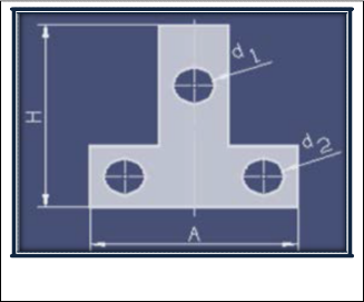
CAD model of the examined detail in our case is presented in figure 1. The model of willing detail is generated in Solid Works as a solid model. However, since the FEM systems of the sheet processing require surface models, then when neces- sary with a simple command is made the transformation which opportunities exist in almost all CAD systems.
Fig. 1. CAD model ready for production
Determining the optimal model especially is important in the determination of the complex contours of the willing detail, where except of the part of the processed contours should be taken into account the contours of the eventual connection of
IJSER © 2013
http://www.ijser.org
the detail parts if it is complex. These are also very important input data’s for simulation of the process which is based on the model given in the experiment.
In order to achieve the objectives in this dissertation paper, all our efforts have resulted in the creation of a program called "prog. Blank" with the help of which is enabled the automa- tion of tool modeling process for processing punching and blanking with the parts of the sheet(. This program has mod- ules which enable the automation of the process of placement the part of the draws in Solid Works.
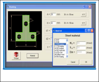
In the beginning the application program allows the paramet- ric input of the characteristic sizes of the willing part, the width (preliminary field is 30 to 50 mm) and the height. De- spite this dimension is given the thickness of the ribbon mate- rial (the field size is from 0.2 to 2 mm).
After the input of the dimensions can be see the part readi- ly in Solid Works with real dimensions of the exterior and in- terior introduced in the program. By providing access to the free tolerances for all dimensions respectively with precise tolerances according to ISO standard 286, for any measure can be defined more precisely the finished part. Through dialogue, to input the material can be transmitted the durability of the material and the cutting length and also elasticity module of the material.
Fig. 3. The parameters of the strip
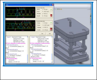
The technological tool parameters passed to the bottom of the Report's where the algorithm can be viewed simultaneously accurate calculation of characteristic sizes and technological parameters. At the end of the Report’s are provided recom- mendations to solve the housing of the tool selection based on all parameters and determined calculated sizes. All calculation is supported by the 3D presentation tool generated one or two parts in one step and can be seen in the working surface.
Fig. 2. The selection of the material
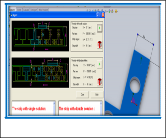
Fig. 4. Process parameters for the placement in both queues parts of the strip
After input the data and the precise definition of the input parameters passed to the dialogue Report, which provides appropriate technological and geometric results that can be transmitted to the 3D environment to obtain the best reflec- tions on the selection offered.
The generating solution of the tool can transmitted construc- tively and technologically in virtual simulations which clearly show the working step of the tool and the movement of the upstream elements of the plate guiding tool and to set all the space that is provided in this step.
By changing the spaces for the respective tool, ∅6 mm, from
IJSER © 2013
http://www.ijser.org
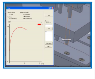
the working diagram in directly can be accompanied the achieved value of the deformation force in the tool for certain elements of the mobile tool depending on the thickness of the material. With this, the process really can be optimize and ver- ify the most important indicators of the process to achieve the state ofexploitation. The space given w = 0.1 mm has a duty to show the position of the curve in the working surface which can be forwarded dependence of force and its maximum from the depth of the penetration of the tool elements. With the introduction of new values of space, depending gained new strength by working step which followed the change in direc- tion of higher values or lower. Any newly inserted value can be deleted to generate and then to verify the new conditions of the deformation.
Fig. 5. The changing of the blanking force
With utilizing the full possibilities of the 3D design, in the whole cross-cutting tool, can be followed the level of the space that is achieved in the virtual model and for any mutual con- tact of the cutting parts of the tool with a strip material.
For the field of the plastic deformation of the metals, the adap- tive methods are considered as standard tools for practical application of the finite element method. Any problem, which is particularly present non-linearity of the physical sizes, nec- essarily requires appropriateness as a fundamental vehicle to obtain acceptable numerical solution.
FEM analysis in the body of the puncher
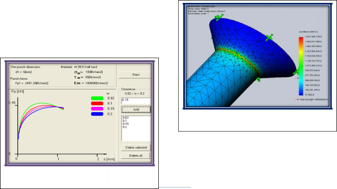
For the analysis of body puncher with Ø6 mm diameter, for punching holes on the material well worth the effort cutter with σ = 400 N/mm2, counted in front of his face acting force constant calculated from 15000 N. From the figure is clearly a biased distribution of the pressure around but the constraints of the small contact area which is the result of constructive of the punching expansion in the part where it connects with the supporting plate, in the force transmitted between plate. Fur- thermore, the puncher in the neck, there is a dangerous area where the concentration of strain is very large and reaches the value 792.248 N/mm2.
With Von Mises’s the strain distribution in the area of maxi- mum value, network with the help of elements of finite preci- sion precision takes the form (Altan & Vasquez, 2000).
By changing the material of the strip and the input of its char- acteristics, incoming acquired completely new conditions of deformation which shows the change of the deformation force to change the space between the working elements of the tool. By setting the parameters of the new introduction possibility of a new analysis which can be fully realized for real condi- tions.
h
Fig. 7. FEM model of the strain distribution according to Von Mises’s with adjusted net
Fig. 6. Dependence of the force of the punch ∅ 8mm in func- tion of the space for Al 99.5
The force which is transmitted through punching body in this case is F=96000 N, and is much more complex contours and very strong cutting edges which are non-linear source. The
IJSER © 2013
ttp://www.ijser.org
first results of the strain analysis with the finite element meth- od in the body of the punching represent the lowest level of the strain achieved but with a significant change in sites where drastic changes are well worth the effort. Results obtained by FEM model are very close to real values if the same criteria is used and the advantages of adaptive h method, figure 8.
Fig. 8. FEM model of displacement in size of the adapt network
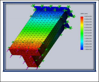
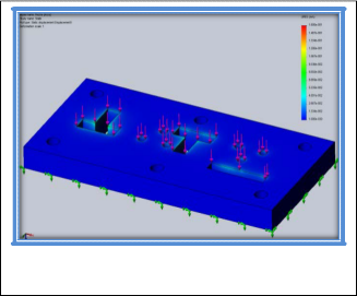
In our case are offered two constructive solutions of the cutter plate, where is obtained one, respectively two parts in one step. These two solutions represent special cases of the static loads. In the static analysis the cutting plates can be treated as a simple beam loaded in flexure. During this analysis, the adaptive method h provides very good results, by adjusting the network of finite elements near the cutting edges with in- tent to obtain more accurate results.
Fig. 9. The displacement fields generated by FEM adaptive h method, for the case in a two step obtained
Based on the outlined tasks in the paper, researches and anal- ysis, in following I will note the contribution and the ad- vantages of our approach in to the assessment and the treat- ment of the design tool process for the metalworking technol- ogy with blanking and punching:
To solve the outlined tasks in the paper is created a code program called "prog. Blank” with whose help is enabled the leadership with the expand CAD model and the automation of the modeling process of the tools for processing the parts with blanking and punching from sheet material. As a platform for the implementation of the expand CAD model of the tool is used the Solid Works CAD application. The program was de- veloped with the idea of creating intelligent components and mechanical connections.
Identification of the critical places of the tool in the design phase, as a source of potential damages enables that the spe- cial elements of the tool should eliminate handled partially or entirely.
Through the experimental evidences that are gained some
characteristic diagrams of the punching force change in the
way of the function of the blanking - punching etc.
References
[1] Sim, S. B., Lee, S. T.,& Jang, H. J., “A study on the Development of Multi- piloting-type Progressive Die for U-bending Part Process,” Jour. of Kore- an Society of Manufacturing Process Engineers, Vol. 2, No. 2pp. 45- 51, 2003.
[2] J. Manuf. Sci. Eng, “Progressive Die Strip Layout Optimization for Mini- mum Unbalanced Moments”, April 2010
[3] P. Picart, A. Touache & J. Chambert, Numerical Simulation The Sheet Metal Blanking Process, CIMNE Barcelona, 2005
[4] T. Altan & V. Vasquez: New Concepts in Die Design – Physical and Computer Modelling, J. of Mat. Proc. Techn., v. 98. (2000) pp. 212-223.
[5] J. Post & R. Voncken, FEM analysis of the punching process, in: Proceed- ings of the Fourth International Conference on Sheet Metal, Twen- te, 1996.
[6] S. Krrabaj, B. Bytyqi, H. Osmani, “Simulation and optimisation of the design process in Function to the clearance between the blanking Tool ele- ments”.16 th International Research/Expert Conference ”,Trends in the Development of Machinery and Associated Technology”. TMT 2012, Dubai, UAE, 10-12 Sept. 2012, ISSN 1840-4944,page. 123-126
[7] M. Tisza: Numerical Modeling and Simulation in Sheet Met- al Forming, Journal of Materials Processing Technology, v.151. (2004) No. 1-3. pp. 58-62.


[8] S. Kumara, and R. Singhb, Automation of strip-layout design for
sheet metal work on progressive die, aDepartment of Mechanical En- gineering, Hindu College of Engineering, Sonepat, Haryana, India,
Received 13 November 2006
[9] S. Krrabaj, B. Bytyqi, H. Osmani, “Influence of Cutting Speed on the Quality of Blanked Parts”, Trends in the development of machinery and associated technology, 15th International research/Expert con- ference; TMT2011,Prague, Czech Republic,12-18Sept. 2011, ISSN1840- 4944,page 817-820.