International Journal of Scientific & Engineering Research, Volume 4, Issue 8, August-2013 903
ISSN 2229-5518
Modeling and Characterization of Supercapaci- tor in Many Power Electronics Application
Rajib Sarkar Rajan, Md.Aminul Islam, B.D.Rahmatullah
Abstract— As a new technology supercapacitors are emerging device for power electronics application. It acts as an energy buffer or energy sources due to their high power density compared to other charge storing devices. In this paper an equivalent circuit model (ECM) is proposed by considering leakage and self-discharge current. Here all the electrical parameters of supercapacitor deduce in two phases
.In first phase we didn’t consider the leakage or self -discharge current and in later phase considered these losses. The proposed model is based on the supercapacitor RC branches model .Moreover, simulation results are presented to prove the validity of this model. This model can be used to determine or predict the actual energy obtained from a supercapacitor. This model also can be used in many industrial applications where supercapacitors act as an energy storage device.
Index Terms— Supercapacitor, Electric Double Layer Capacitor (EDLC), Equivalent Circuit Model (ECM), Leakage Loss, Self Discharge
Loss, Kirchhoff’s voltage law (KVL),Laplace Transform ,Inverse Laplace Transform
—————————— ——————————
1 INTRODUCTION
n the contemporary world energy has become a primary focus of the major power and scientific community due to the changing global scenario. There has been great

interest in developing and refining more efficient energy storage devices. Conventional batteries and capacitors are widely used for energy storing. Although conventional batteries have very high energy density but the lower cyclic lifetime and low power density restricts their application in high power system [1]. The instantaneous discharging be- havior and low energy density reduce the reliability of the conventional capacitors in many applications. Compared with batteries and conventional capacitors, supercapacitors are more preferable due to their high-efficiency, light- weight, larger current density, wider working temperature range, less maintenance and environmental friendly [1]. To compare the performance of different storage devices Ragone plot is given below.
.
.
Fig.1. Comparison of storing devices using Ragone plot
————————————————
• Rajib Sarkar Rajan completed his B.Sc. in Electrical and Electronic Engi- neering from University of Asia Pacific , Bangladesh ,E-mail: rajanrajib@gmail.com
• Md. Aminul Islam completed his B.Sc. in Electrical and Electronic Engi- neering from University of Asia Pacific , Bangladesh , E-mail: aminul_eee09.tan@yahoo.com
• B. D. Rahmatullah is a consultant of UNDP (BRESL Project), Bang-
ladesh , , E-mail: bdrahmatullah@gmail.com
Considering all these advantages supercapacitors have be- come an attractive power solution for an increasing num- ber of applications such as electric/hybrid electric vehicles, fuel cell vehicles, computer systems, UPS systems and power conditioners etc. Moreover, supercapacitors can be used for desalting water based on periodic sorption and desorption of ions on the extensive surface of porous elec- trode based on its capacitive properties [2], [3]. To reduce the time and costs for physical experimentation, the scien- tific community has exploited equivalent circuit modeling to predict characteristics of supercapacitors. In this paper an equivalent circuit model (ECM) is proposed to represent the characteristics of EDLC. This model is based on the supercapacitor RC branches model which is useful for most of the studies and applications [4], [5]. Here we developed all the electrical parameters of supercapacitor without and with considering leakage or self-discharge phenomenon respectively. This model was validated with supercapaci- tors simulation plots. In this paper we first introduce ener- gy storing principle of supercapacitor and equivalent cir- cuit models in section II. In section III we have discussed about proposed method and validity of this model is also presented in this section. Conclusion of this study is given in section IV.
2 ABOUT SUPERCAPACITOR
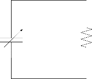
2.1 Energy Storage Principle
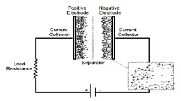
Fig.2. Charge storage principle of supercapacitor
IJSER © 2013 http://www.ijser.org
International Journal of Scientific & Engineering Research, Volume 4, Issue 8, August-2013 904
ISSN 2229-5518
Supercapacitors are constructed from two carbon based electrodes, an electrolyte, and a separator. Fig.2 represents the charge storage principle of supercapacitor. Like con- ventional capacitors, supercapacitors also store charge elec- tro statically, and there is no transfer of charge between electrode and electrolyte. When voltage is applied, an elec- tric field is created in the electrolyte which causes polariza- tion in the electrolyte. Due to the natural attraction of un- like charges, ions in the electrolyte diffuse across the sepa- rator into the pores of the electrode of opposite charge. Thus, a double-layer of storing charge is produced at each electrode. As a result surface area is increased and decreas- es the distance between electrodes, which allow superca- pacitor to achieve higher energy densities than convention- al capacitors [9],[10],11]. Electric energy was stored into the electrical double layer which was formed at the porous sol- id electrode/electrolyte interface [6].Here separator acts as an insulator which prevents physical contact of electrodes but allows ion transfer between them [7]. Energy storing capacity of supercapacitor does not depend only on the specific surface area of electrode materials, but it also de- pends on the utilization rates of micro-hole of the porous electrode and the active materialism electrolyte [8].Different types of carbon materials used as an electrode such as activated carbon, carbon aero gels, carbon nano- tubes and metal oxides. As an electrolyte aqueous H2SO4 or KOH is used.
2.2 Supercapacitor Equivalent Circuit Model
The purpose of equivalent circuit model is to represent the characteristics of supercapacitors in many power electron- ics applications. Three major considerations take into ac- count before modeling equivalent circuit structure.
1. The model structure should be related to the physics of the device, but it should be as simple as possible to provide the engineer with a practical tool for design.
2. The model should describe the terminal behavior of the supercapacitor over the range of 30 min with sufficient ac- curacy.
3. It should be possible to determine the parameters of the proposed model using measurements at the supercapacitor terminals [4].
Equivalent circuit models are mainly classified into three catego-
ries. These are RC circuit model, supercapacitor RC branches model and a transmission line model. In this paper
Based on the physics of the device, supercapacitors mod- eled as an RC circuit. In fig.3 resistive element represents
the resistivity of the electrode (carbon particles) materials
of the supercapacitor and capacitive element represents the
capacitance between carbon particles and electrolyte. Ca-
pacitance of the supercapacitor depends on potential dif-
ferences across the material [3]. To represent this voltage
dependence capacitance immediate branch is modeled as a
voltage dependent differential capacitor. This capacitor is
modeled as a constant capacitor 𝐶𝑜 , with a parallel capaci- tor 𝐶𝑢 , which is linearly dependent on the voltage 𝑉𝑐 across
it [12].
𝑪 𝒗 = 𝑪𝒐 + 𝑲𝒗⃒𝑽𝒄 ⃒ (1)
Parameter 𝐾𝑣 depends on numerous parameters, such as
pore sizes, membrane porosity and packaging technology
[4] and having the unit of Farad/V. This immediate branch
represents the behavior of the supercapacitor in the time
range of seconds in response to a charge action. The de-
layed branch with parameters 𝑅𝑑 , 𝐶𝑑represent the behavior
in the time range of minutes and the long term branch with
parameters𝑅𝑛 , 𝐶𝑛 represent the behavior in the time range more than 10 minutes .A leakage resistor𝑅𝑙 parallel to the
terminal represents leakage loss or self-discharge loss of a
supercapacitor.
3 PROPOSED MODELING AND VALIDITY OF THE MODEL
In this paper an equivalent circuit model is presented which is used to determine the actual behavior of superca- pacitor in many power electronics application. During the dynamic charge and discharge process a small amount of current known as self-discharge current induced by leak-
age resistance𝑅𝑙 . So only the immediate branch and leak-
age resistance is considered in this paper.
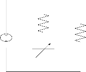
3.1 Modeling of Charging Process
RS
Rl
Vin
Fig.3: Supercapacitor RC branches model
CV
Fig.4. Modeling of charging process
We start the analysis by applying Kirchhoff’s voltage law; the input voltage must be equal to the voltage drop over the resistor, plus the voltage across the capacitor. This can be expressed mathematically as,
𝑽𝒊𝒏 = 𝑽𝑹𝑺 (𝒕) + 𝑽𝒄(𝒕) (2)
IJSER © 2013 http://www.ijser.org
International Journal of Scientific & Engineering Research, Volume 4, Issue 8, August-2013 905
ISSN 2229-5518
Voltage across capacitor,
And from equation (9), (11), (12) & (13) we get the actual charging energy
𝟏 𝒕
−𝒕

𝑽𝒄(𝒕) = 𝑪 ∫𝒐 𝒊(𝒕)𝒅𝒕 + 𝑽𝒄 (𝟎) (3)
Therefore (2) becomes,

𝑬𝒂𝒄 = 𝑬𝒄 − 𝒊𝒍 �𝒕 + 𝑹𝒔 𝑪𝒗 �𝒆
𝑹𝒔 𝓒
− 𝟏�� (14)
𝟏 𝒕
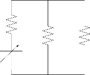
3.2 Modeling of Discharging Process

𝑽𝒊𝒏 = 𝒊(𝒕) ∗ 𝑹𝒔 + 𝑪 ∫𝒐 𝒊(𝒕)𝒅𝒕 + 𝑽𝒄(𝟎) (4)
In this 𝑉𝑐 (0) refers to the initial voltage of the capacitor and
𝑖(𝑡) is the charging current. This current must be obtained RS
before the capacitor voltage can be calculated. So by apply-
ing Laplace and Inverse Laplace Transform in (4) we get
Charging current,
CV
Rl RL

𝒊(𝒕) = [𝑽𝒊𝒏 −𝑽𝒄(𝟎)]
𝑹𝒔
If 𝑉𝑐 (0) negligible then,
−𝒕

−𝒕
* 𝒆𝑹𝒔∗𝓒 (5)
Fig.5. Modeling of discharging process

𝒊(𝒕) = 𝑽𝒊𝒏
𝑹𝒔

* 𝒆𝑹𝒔 ∗𝓒 (6)
During discharging process, supercapacitor 𝐶𝑣 acts as a
From (3) & (6) we get the charging voltage,

−𝒕
𝑽𝒄 (𝒕) = [𝑽𝒊𝒏 − 𝑽𝒄(𝟎)] 𝒆𝑹𝒔 ∗𝓒 + 𝑽𝒄(𝟎) (7)
If 𝑉𝑐 (0) is negligible (7) becomes
power source and we consider it will discharge through a
load 𝑅𝐿 . Fig.5 can be simplified as,

−𝒕
𝑽𝒄(𝒕) = 𝑽𝒊𝒏 �𝟏 − 𝒆𝑹𝒔∗𝓒 � (8)
This represents the charging voltage without considering leakage
loss. Leakage current flowing through the 𝑹𝒍
𝑽𝒊𝒏
CV Req
𝒊𝒍 =
So the actual charging current,

𝑹𝒍
Fig.6. Simplified discharging circuit
Where, 𝑹𝒆𝒒 = 𝑹𝒔 + (𝑹𝒍 ∥ 𝑹𝑳 ) .By applying KVL we can write in
𝒊𝒂𝒄 = 𝒊(𝒕) − 𝒊𝒍 (9)
Equation (9) can be written as,
−𝒕
this circuit,
𝑸(𝒕)

�𝑽𝒊𝒏 𝒆𝑹𝒔∗𝓒 − 𝑽𝒊𝒏� = 𝑪
𝒅𝑽𝒄 (𝒕)
(10)

𝑪 − 𝒊(𝒕)𝑹𝒆𝒒 = 𝟎 (𝟏𝟓)


𝑹𝒔
𝑹𝒍𝒌

𝒗 𝒅𝒕 𝒗
By taking integral on both sides we get the actual charging voltage
Here 𝑖(𝑡) is the total discharging current and 𝑄(𝑡) is the
amount of charge stored during charging process. Again,

𝑽 (𝒕) = 𝑽 [ 𝟏 − 𝒕 − 𝒆
𝒂𝒄 𝒊𝒏 𝑹𝒍 𝑪

−𝒕
𝑹𝒔∗𝓒
] (11)
𝒅𝑸

𝒊(𝒕) =
𝒅𝒕
(𝟏𝟏)
As energy is the integral of voltage and current, so the en- ergy of a supercapacitor is
𝒕
Plug (16) into (15), total discharging current is expressed as

𝒊(𝒕) = 𝑽𝒄 (𝒕) 𝒆−𝒕/𝑹𝒆𝒒𝑪𝒗 (17)
𝑹𝒆𝒒
𝑬 =∫𝒐 𝑽(𝒕)𝒊(𝒕)𝒅𝒕
(12)
From equation (6), (8) & (12) we get the charging energy without considering leakage
But a portion of this discharging current will flow through the leakage resistor which is appeared as a self-discharge loss. So the actual current flowing through the load is


−𝒕
𝟐
−𝟐𝒕
𝑬𝒄 = 𝑪𝒗 𝑽𝒊𝒏 �−𝒆𝑹𝒔 𝓒 + 𝟎. 𝟓 + 𝟎. 𝟓𝒆𝑹𝒔𝓒 � (13)
IJSER © 2013
http://www.ijser.org
International Journal of Scientific & Engineering Research, Volume 4, Issue 8, August-2013 906
ISSN 2229-5518

𝑖 (𝑡) = 𝑅𝑙
𝑅 +𝑅
𝑖(𝑡) (18)
1094
1093
Charging Energy
Without Leakage
With Leakage
𝑙 𝐿
1092
Predicted energy of the load is 𝑬𝑳 = ∫ 𝒊𝟐 (𝒕)𝑹𝑳 𝒅𝒕
1091
1090
1089

𝑽 𝒄(𝒕) 𝟐 𝑹𝒆𝒒 𝑪𝒗

−𝑹
𝟐𝒕
1088
1087
𝑬𝑳 = ( )
𝒆𝒒
𝟐 𝑹𝑳 �𝟏 − 𝒆
𝒆𝒒𝑪𝒗 � (𝟏𝟏)
1086
200 300 400 500 600 700 800
Time[S]
But a portion of this energy wills loss due to self-discharge,
so the actual energy of the load is
𝑡
𝐸𝐿 = � 𝑖2 (t)𝑅 𝑑𝑡
0
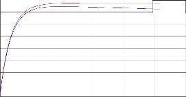
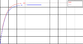
Fig.7. Validity of modeling during charging process
The proposed method was validated with supercapacitor charging and discharging plots. In all these plots we can see that two colors plots, one is red which represent meas-
𝑬 = ( 𝑹𝒍 𝑽𝒄 (𝒕)
𝑳 (𝑹 + 𝑹 )𝑹

)𝟐 𝑹𝒆𝒒 𝑪𝒗 𝑹 �𝟏 − 𝒆
𝟐 𝑳
−𝑹

𝟐𝒕
𝒆𝒒𝑪𝒗 � (𝟐𝟎)
urement of parameters without considering leakage and another is blue color represent measurement with consider-
𝒍 𝑳
𝒆𝒒
ing leakage. In this modeling we tried to show the actual
condition of supercapacitor charging and discharging pa-
rameters by considering leakage or self-discharge property
3.3 Validity of this Proposed Model
To prove the validity of proposed modeling we used BCAP350
D Cell supercapacitor
Table 1
Parameters of BCAP350 D Cell
and we also differentiated these measurement with the pa- rameters where these loss was not accounted. We can see that in Fig.7 charging voltage and energy curve after a cer- tain point start to decrease. This is because at that point supercapacitor is fully charged. If we continue the supply after this point voltage or energy will be decreased due to
unnecessary current flow through 𝑅𝑙 . From charging cur-
rent plot it is observed that after a fully charged point cur-
rent will go negative region. This represents that after that
point actual charging current is almost zero but an unnec-
essary current due to the extra charging causes falling of
the original current.
0.014
0.012
Load Current
Without Leakage
With Leakage
0.09
0.08
Charging Current
Without Leakage
With Leakage
0.01
0.008
0.07
0.06
0.05
0.006
0.004
0.04
0.002
0.03
0.02
0
0 0.5 1 1.5 2 2.5 3
0.01
0
1200
Time[S]
Energy Of Load
5
x 10
-0.01
200 300 400 500 600 700 800
ChargTinimge[VS]oltage
1000
Without Leakage
With Leakage
2.5
2.499
2.498
2.497
2.496
Without Leakage
With Leakage
800
600
400
2.495
200
2.494
2.493
2.492
2.491
200 300 400 500 600 700 800
Time[S]
0
0 0.5 1 1.5 2 2.5 3 3.5 4 4.5 5
Time[S]
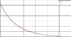
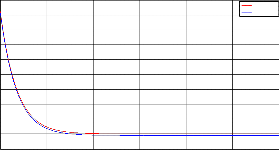
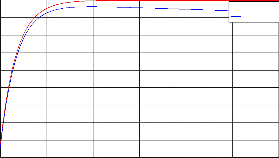
Fig.8. Validity of modeling during discharging process
IJSER © 2013 http://www.ijser.org
International Journal of Scientific & Engineering Research, Volume 4, Issue 8, August-2013 907
ISSN 2229-5518
During discharging supercapacitor acts as an internal pow- er source, and it will discharge through a load. In this pa- per as a load we used a resistance of 200Ω which is repre-
sented by 𝑅𝐿 . Top plot in Fig.8 we can see that load cur-
rent is slightly went down denoted by blue color compared
to red color current curve which should flow through the
load. This is due to self-discharging current. Although it is
desirable total energy of a charged supercapacitor will dis-
sipate through the load but due to self-discharge loss a
small amount of energy is lost and the actual energy curve
represented by blue color is slightly went down compared
to red color.
5 CONCLUSIONS
What is the basic difference between a capacitor and superca- pacitor? Both can store energy while one discharges instanta- neously the other tends to discharges in a way similar to that of a battery. But if it does so, it shall be better than a battery because it is much more environment friendly, less expensive and more over maintenance and hazard free. All these quali- ties have driven the scientists and engineers worldwide to modeling and developing the design of supercapacitors for application in power and electronic engineering. In reality supercapacitors are advanced version of conventional capaci- tors. So our effort in modeling and developing the supercapac- itor is also participating with the world scientists and engi- neers in an effort to develop the model of a supercapacitor. In this paper an equivalent circuit model is proposed considering leakage or self-discharge loss. This model can be used to ob- serve the actual behavior of supercapacitor in many power electronics application.
ACKNOWLEDGMENT
We would like to express our gratitude to Sazzadur Rahman, Khondoker Sultan Mahmood and Arif Shariar for their kind supervision and support in this paper .
REFERENCES
[1] Ran Niu and Hai Yang, “Modeling and Identification of Electric Double Layer Supercapacitors”, ICRA Communication ( IEEE Con- ference ), pp. 1 -4 , 2011.
[2] A..M. Johnson and J. Newman, “Desalting by Means of Porous Car- bon Electrodes”, J. Electrochem. Soe.,vol. 118, pp. 510-517, 1971.
[3] Y. Oren, “Capacitive deionization (CDI) for desalination and water treatment - past, present and future (a review)”, Desalination, vol.
228, pp. 10-29, 2008.
[4] L.Zubieta and R. Bonert, “Characterization of double-layer superca- pacitors for power electronics applications”, IEEE Trans. on Industry Applications, vol. 36, pp. 199-205, 2000.
[5] P. Barrade, “Energy storage and applications with supercapacitors” [6] Z. Li, C. Jie, “An impedance-based approach to predict the state-
ofcharge for carbon-based supercapacitors”, Microelectronic Engi- neering,vol. 85, pp. 1549-1554, 2008.
[7] O.H. LeBlanc, Mathematics of Ultracapacitors, GE Global Research, Technical Report, June 1993.
[8] F.Belhachemi, S. Rael and B. Davat, “A physical based model of
power electric double-layer supercapacitors”, Industrial Application
Conference, vol. 5, pp. 3069-3076, 2000.
[9] Conway, B. E. (1999). Electrochemical Supercapacitors : Scientific Fundamentals and echnological Applications.New York, Kluwer- Plenum.
[10] Burke, A. (2000). "Ultracapacitors: why, how, and where is the tech- nology." Journal of Power Sources 91(1): 37-50.
[11] Kotz, R. and M. Carlen (2000). "Principles and applications of electro- chemical capacitors." ElectrochimicaActa 45(15-16): 2483-2498.
[12] R.Gallay, A. Schnewly and V. Hermann, “High performance double layer capacitors for power electronics applications”, PCIM2001, Pow- er Quality, Nurnberg, Germany
IJSER © 2013 http://www.ijser.org