International Journal of Scientific & Engineering Research Volume 2, Issue 11, November-2011 1
ISSN 2229-5518
Mitigation of Harmonics in Distribution System
Using D - STATCOM
E.Rambabu, E.Praveena, Prof.P.V.Kishore
Abstract— This paper deals with the performance, analysis of, operating principles of a new generation of power electronics based equipment called Distribution Static Compensator (D-STATCOM) aimed at enchancing the reliability, and quality of power flow in low vol- tage distribution network. The model is based on the Voltage Source Converter (VSC) principle. The D-STATCOM injects a current into the system to mitigate the voltage sags.LCL Passive Filter was then added to D-STATCOM to improve harmonic distortion and low power factor.
Index Terms— D-STATCOM, Power Quality, Voltage sag, Voltage source converter, harmonic distortion
—————————— ——————————
n the early days of power transmission in the late 19th century problems like voltage deviation during load changes and power transfer limitation were observed due to reactive power unbalances. Today these Problems have even higher impact on reliable and secure power supply in the world of Globalization and Privatization of electrical systems and energy transfer. The development in fast and reliable semiconductors devices (GTO and IGBT) allowed new power electronic Configurations to be introduced to the tasks of power Transmission and load flow control. The FACTS devices offer a fast and reliable control over the transmission parameters, i.e. Voltage, line impedance, and phase angle between the sending end voltage and receiving end voltage. On the other hand, the custom power is for low voltage dis- tribution, and improving the poor quality and reliability of supply affecting sensitive loads. Custom power devices are very similar to the FACTS. Most widely known custom power devices are DSTATCOM, UPQC, DVR among them DSTAT- COM is very well known and can provide cost effective solu- tion for the compensation of reactive power and unbalance
loading in distribution system
The performance of the DSTATCOM depends on the control algorithm i.e. the extraction of the current components. For this purpose, there are many control schemes, which are reported in the literature, and some of these are instantaneous reactive power (IRP) theory, instantaneous compensation, in- stantaneous symmetrical components, synchronous reference frame (SRF) theory, computation based on per phase basis, and scheme based on neural network. Among these control schemes, instantaneous reactive power theory and synchron- ous rotating reference frame are most widely used. This paper focuses on the compensating the voltage sag, swells and mo- mentary interruptions.
In this paper, the configuration and design of the DSTATCOM with LCL Passive Filter are analyzed. It is connected in shunt or parallel to the 11 kV test distribution system. It also is design to enhance the power quality such as voltage sags, harmonic distortion and low power factor in dis- tribution system.
Voltage sag or dip represent a voltage fall to 0.1 to 0.9 p.u. and existing for less than one minute and voltage swell is the rise in voltage of greater than 1.1 p.u. and exists for less than one minute.
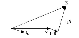
Fig: 2.1 Uncompensated Line with Single Load
First, we consider an uncompensated line.The current drawn by a load depends on the load itself and the line vol- tage. The current engenders the voltage drop in the transfor- mer and the line reactance. It results in decrease in transmis- sion voltage VT and distribution voltage VD. Figure 2.1 shows the vector diagram of a single load center connected to un- compensated line. The voltage drop in the line mainly de- pends on the current taken by the load as well as the resis- tance and inductance in the line.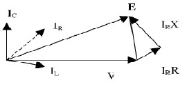
Fig: 2.2 Compensated Lines with Single Load
IJSER © 2011
International Journal of Scientific & Engineering Research Volume 2, Issue 11, November-2011 2
ISSN 2229-5518
It can also be seen that the angle between the voltage and the current is playing a major role in maintaining the voltage. Let us consider the supply voltage is E. Now due to the vol- tage drops IR and IX the load voltage is V.
It is possible to bring V=E, just by making the current to lead so that the vector diagram will get modified as shown in figure 2.2. i.e by the use of shunt compensation (either at the transmission line or at the distribution line) the voltage at the load end can be regulated.
The same principle can be used in case of capacitive load also. If the load is capacitive, a lagging current will help in regulation of voltage.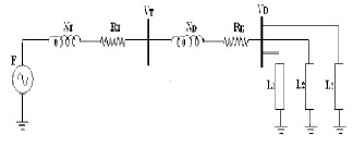
Fig: 2.3 A Simple power line without DSTATCOM
From the above figure 2.3 it is clear that the voltage will get dropped both at the transmission side as well as at the distri- bution side.
E < VT < VD
Hence by the use of reactive power compensation VD can be increased to that of the supply voltage E.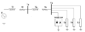
Fig: 2.4 A Simple power line with DSTATCOM
As DSTATCOM is the shunt device the shunt –injected cur- rent (leading or lagging) corrects the voltage by adjusting the voltage drop and
VD = E
The indictive or capacitive reactive power required by the load is provided at the load point itself by the STATCOM without the use of reactors and capacitive banks.
A D-STATCOM consists of a two-level VSC, a dc energy sto- rage device, controller and a coupling transformer connected in shunt to the distribution network. Figure 3.1 shows the schematic diagram of D-STATCOM.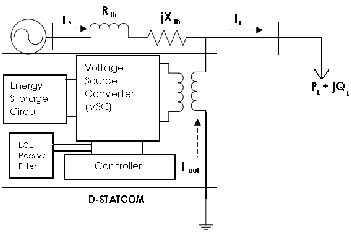
Fig: 3.1 Schematic diagram of a DSTATCOM
Iout = IL – IS =IL – ((Vth - VL)/Zth) (1) Iout < γ = IL < (-θ) – (Vth/Zth) < (δ-β) + VL/Zth < (-β) (2)
Iout =Output current IS = Source current IL = Load current
Vth = Thevenin voltage
VL = Load voltage
Zth = Impedance
Referring to the equation 2.2, output current, Ioutwill correct the voltage sags by adjusting the voltage drop across the sys- tem impedance, (Zth =R+jX). It may be mentioning that the effectiveness of D-STATCOM in correcting voltage sagsde- pends on:
a) The value of Impedance, Zth = R+jX
b) The fault level of the load bus
A voltage-source converter is a power electronic device that connected in shunt or parallel to the system. It can gener- ate a sinusoidal voltage with any required magnitude, fre- quency and phase angle. The VSC used to either completely replace the voltage or to inject the ‘missing voltage’. The ‘miss- ing voltage’ is the difference between the nominal voltage and the actual. It also converts the DC voltage across storage de- vices into a set of three phase AC output voltages [8, 9].
IJSER © 2011
International Journal of Scientific & Engineering Research Volume 2, Issue 11, November-2011 3
ISSN 2229-5518
In addition, D-STATCOM is also capable to generate or
absorbs reactive power. If the output voltage of the VSC is greater than AC bus terminal voltages, D-STATCOM is said to be in capacitive mode. So, it will compensate the reactive power through AC system and regulates missing voltages. These voltages are in phase and coupled with the AC system through the reactance of coupling transformers.
Suitable adjustment of the phase and magnitude of the DSTATCOM output voltages allows effectives control of ac- tive and reactive power exchanges between D-STATCOM and AC system. In addition, the converter is normally based on some kind of energy storage, which will supply the converter with a DC voltage [10].
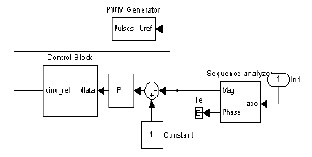
Fig: 3.2 Bolck diagram of Controller System
Figure 2.2 shows the block diagram of Controller sy tem.The controller system is partially part of distribution sy tem.
Proportional-integral controller (PI Controller) is a feedback controller which drives the system to be controlled with a weighted sum of the error signal (difference between the output and desired set point) and the integral of that val- ue.
In this case, PI controller will process the error signal to zero. The load r.m.s voltage is brought back to the reference voltage by comparing the reference voltage with the r.m.s vol- tages that had been measured at the load point. It also is used to control the flow of reactive power from the DC capacitor storage circuit.
PWM generator is the device that generates the Sinu- soidal PWM waveform or signal. To operate PWM generator, the angle is summed with the phase angle of the balance supply voltages equally at 120 degrees. Therefore, it can pro- duce the desired synchronizing signal that required. PWM generator also received the error signal angle from PI control-
ler. The modulated signal is compared against a triangle signal
in order to generate the switching signals for VSC valves.
For the simulation study a three phase source is treated as primary distribution substation and the distribution line is treated as the lumped inductance in series with the resistance. Let us consider a fixed load is connected to the distribution line and a heavy inductive and capacitive load is connected at the required instants to study the performance the DSTAT- COM in case of voltage sag and swell conditions. The DSTAT- COM circuit is connected in shunt with the distribution sys- tem nearer to the load point through a star/delta transformer.
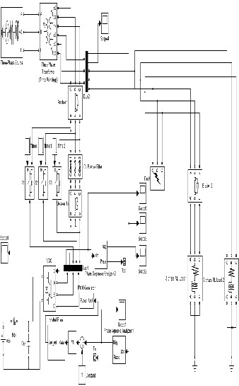
Fig: 5.1 Simulink diagram of main power system network
IJSER © 2011
International Journal of Scientific & Engineering Research Volume 2, Issue 11, November-2011 4
ISSN 2229-5518
In this paper inorder to create a disturbance in the system we used a three phase fault block from simulink. The different faults created in the system are Single Line to Ground (SLG), Line to Line (LL), Double Line to Ground (DLG), Three phase to Ground (TPG).
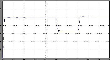
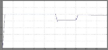
Fig: 6.1(d) Simulation result for SLG
TABLE 1
VOLTAGE SAGS FOR DIFFERENT FAULT CONDITIONS
Fault Re- sistance Rf(Ω) | Volyage sags fot TGP Fault | Volyage sags fot DLG Fault | Volyage sags fot LL Fault | Volyage sags fot SLG Fault |
0.66 | 0.66 | 0.70 | 0.75 | 0.82 |
0.76 | 0.71 | 0.74 | -.79 | 0.84 |
0.86 | 0.75 | 0.78 | 0.82 | 0.86 |
Fig: 6.1(a) Simulation result for TGP
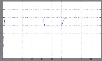
Fig: 6.1(b) Simulation result for DLG
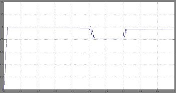
Fig: 6.1(c) Simulation result for LL
The above table shows the overall results of voltage sags in p.u. for different types of fault. From the table, it can be ob- served that when the value of fault resistance is increase, the voltage sags will also increased for different types of fault.
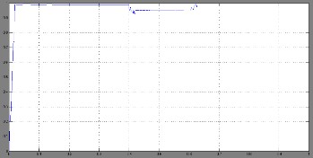
Fig: 6.2(a) Simulation result for TGP
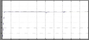
Fig: 6.2(b) Simulation result for DLG
IJSER © 2011
International Journal of Scientific & Engineering Research Volume 2, Issue 11, November-2011 5
ISSN 2229-5518
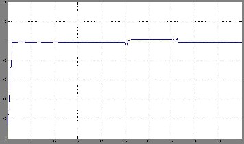
Fig: 6.2(c) Simulation result for LL
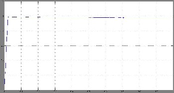
Fig: 6.2(d) Simulation result for SLG
TABLE 2
VOLTAGE SAGS FOR DIFFERENT FAULT CONDITIONS
Table 2 shows the overall results of voltage sags in p.u with different types of fault. From the table, it can be observed that voltage sags improved with insertion of D-STATCOM. The value of voltage sags is between (0.9 to 1.02 p.u.)
TABLE 3
DIFFERENT TYPES OF FAULTS BEFORE AND AFTER D-STATCOM
WHEN RF = 0.6Ω
The power Quality improvement by using Distribution Static Compensator is presented in this paper.The results validate the principle if D-STATCOM for voltage regulate- on applications. The simulation results show that the vol- tage sags can be mitigate by inserting D-STATCOM to the distribution system.
We are thankful to T.Vijay Muni, Assistant Professor in Deapartment of Electrical and Electronics Engineering of NRI Institute of Technology, Agiripalli, India with whom we had useful discussions regarding Power Quality using D-STATCOM. Any Suggestions for futher improvement of this topic are most welcome
[1] Haque, M.H., “Compensation Of Distribution Systems Voltage sags by DVR and D-STATCOM”, Power Tech Proceedings, 2001 IEEE Porto, Volume 1, PP.10-13, September 2001.
[2] J.Nastran , R. Cajhen, M. Seliger, and P.Jereb,”Active PowerFilters for Nonlinear AC loads, IEEE Trans.on Power ElectronicsVolume 9, No.1, PP: 92-96, Jan 2004.
[3] R.Meinski, R.Pawelek and I.Wasiak, “Shunt Compensation For Power Quality Improvement Using a STATCOM controller Modelling and Simu- lation”, IEEE Proce, Volume 151, No. 2, March 2004.
[4] M.Madrigal, E.Acha., “Modelling OF Custom Power Equipment Using
Harmonics Domain Twchniques”,IEEE 2000
[5] Babri Ivoand Jones, “a new three –phase low THD supply with High –
frequency isolation and 60v/200A regulated DC supply”. 2001. IEEE
[6] R. Strzelecki, H. Supronowicz: Power factor in AC supply systems and improvements methods, publishing house of the Technical Uni- versity of Warszawa, Warszawa 2000
BIOGRAPHIES
Mr. E. rambabu has obtained his B.Tech degree from J.N.T.University india,in 2006 and pursuing M.tech degree from MIST college under J.N.T.U affilia- tion,Andhrapradesh,India
Mrs. E. Praveena has obtained her B. Tech degree from S.V. University India, in 2002 and M. Tech degree From S. V. Uni- versity India, in 2007. She has 6 years of teaching experience
Mr. P. Venkata Kishore has obtained his B. Tech degree from S.V. University India, in 1998 and M. Tech degree From S. V. University India, in 2003. He has 13 years of teaching experience. He is presently a research scholar at Satyabhama University, Chennai, India. He is working in the area of D-STATCOM
IJSER © 2011