International Journal of Scientific & Engineering Research, Volume 5, Issue 12, December-2014 164
ISSN 2229-5518
Microcontroller Based Solar Tracking System and its Implementation
Sara Sunny, Anumol Jose,Jithin K,Joseph Jose,Jitha Joseph
Abstract— Sun is a very abundant source of power. Even so, only a fraction of the entire energy is harnessed and that too not efficiently. The main cause of this is the high cost of installation of solar cells. Also solar cells are mostly kept fixed, so they do not obtain the optimum amount of sunlight throughout the day.A new micro-controller based solar-tracking system is proposed implemented and tested. The scheme presented here can be operated as independent of the geographical location of the site of setting up. The system checks the position of the sun and controls the movement of a solar panel so that radiation of the sun comes normally to the surface of the solar panel. The developed-tracking system tracks the sun in the single plane. PC based system monitoring facility is also included in the design. In this paper we have proposed a single axis tracker for our discussions. This avoids the complexity of construction and usage
Index Terms— PIC microcontroller, photocell, one-axis tracking, solar energy, dc drives,LDR,RISC CPU
1.INTRODUCTION
—————————— ——————————
Currently, many alternative energy sources appear to be technically feasible. One of them is solar en- ergy.panels are fundamental solarenergy conver- sion component. Conven tional solar panels fixed with a certain angle, limits their area of exposure from the sun during the course of the day There- fore, the average solar energy is not always maxim- ized. Solar Tracking systems are essential for many application such as thermal energy storage systems and solar energy based power generation systems in order to improve system performance. The change in sun’s position is monitored, and the sys- tem always keeps that the plane of the panel is normal to the direction of the sun. The solar tracker designed and constructed in this paper offers a reliable and affordable method of aligning a solar panel with the sun in order to maximize its energy output. The sun tracker system is a hybrid hard- ware and software prototype designed around Programmable Intelligent Computer (PIC), which automatically provides best alignment of solar panel with the sun. Two Cadmium Sulfide (CdS) photo resistors are used to sense the light intensity. The CdS photo resistors are light dependent resis- tor(LDR),it is basically a photocell that is sensitive to light (7) . Software developed which would allow the PIC to detect and obtain its data from the three CdS or LDR cells ( sensor A,sensor B and sensor C) and then compare their resistances. The three sensors will be positioned in such a way, so that if one of the two comes under a shadow

,the pic microcontroller will be dectect the differ- ence in resistence and thus actuate the motor to move the solar panel into a position where nthe lighit upon both sensers is equal.
Fig.1 Block diagram of the proposed solar tracking system
2. DESIGN OF THE SOLAR TRACKING SYSTEM
The tracker control system contains a control
board, a control program, a power supply board, one motor interface board and a set of sensors. The block diagram consists of a microcontroller, three ldr ’s connected to any of the ports of microcontrol- ler, voltages from LDR is analog therefore an ADC
is used to convert analog voltage to digital because
IJSER © 2014 http://www.ijser.org
International Journal of Scientific & Engineering Research, Volume 5, Issue 12, December-2014 165
ISSN 2229-5518
microcontroller accepts only binary inputs. Micro- controller is then interfaced with a stepper motor using an voltage /current driver , because amount of current required to drive the stepper motor is
10ma but microcontroller provides only 2ma. A solar panel is connected to the stepper motor, which allows the panel to rotate in the direction where sunlight is maximum. Solar panel or photo voltaic cell is a transducer which converts solar energy into electrical energy. As solar energy is vastly available it is going to play an important role as a conventional resource of energy. But when compare to other sources of energy like thermal, hydel etc... Its efficiency is very less. As the direc- tion of sun changes from time to time each panel has to be rotated accordingly in order to get better efficiency. Maintaining it manually is a huge job. The main theme of our project is to rotate the panel automatically by using sensors and stepper motor
2.a)THE LIGHT DEPENDENT RESISTORS
To track the sun , the system should work in closed loop form, the controller needs to sense the light through a light sensor. For this purpose a light dependent resistor (LDR) were used. The LDR consists of a disc of semi conductor material with two electrodes on its surface. In the dark or in dim light, the material of the disc has a relatively small number of free electrons in it. There are few electrons to carry electric charge. This means that it is poor conductor of electric current; Its resistance is high. In the light, more electrons escape from the atoms of the semicon- ductor. There are more electrons to carry electric charge. It becomes a good conductor; Its resistance is low.
ARCHITECTURE
The PIC16F84A microcontroller has been one of the most popular PICMicro controllers for a very long time. This is an 18-pin device and it offers 1024 x 14 flash program memory, 36 bytes of data RAM, 64 bytes of non-volatile EEPROM data memory,13 I/O pins, a timer, watchdog , and internal and external interrupt sources. The timer is 8-bits wide but can
2.4 Special Microcontroller Features:•
• 100,000 erase/write cycle Enhanced Flash
be programmed to generate internal interrupt.
A resistor capacitor can also be used as a timing device for applications where accurate timing is not required.
High-Performance RISC CPU:
•Only 35 single-word instructions to learn• All single-cycle instructions except for program branches, which are two-cyc Operating speed: DC – 20 MHz clock input DC – 200 ns instruction cycle
•Up to 8K x 14 words of Flash Program
•Memory, Up to 368 x 8 bytes of Data Memory
(RAM),
2..2 Peripheral Features:
Timer0: 8-bit timer/counter with 8-bit prescaler
Timer1: 16-bit timer/counter with prescaler , can be incremented during Sleep via external crystal/clock .
Timer2: 8-bit timer/counter with 8-bit period register, prescaler and postscaler
Two Capture, Compare, PWM modules
- Capture is 16-bit, max. resolution is 12.5 ns
- PWM max. resolution is 10-bit
2.3Analog Features:
•10-bit, up to 8-channel Analog-to- Digital Converter (A/D)
•Brown-out Reset (BOR)
•Analog Comparator module with:
- Two analog comparators
- Programmable on-chip voltage refer- ence (VREF) module
program memory typical
IJSER © 2014 http://www.ijser.org
International Journal of Scientific & Engineering Research, Volume 5, Issue 12, December-2014 166
ISSN 2229-5518
• 1,000,000 erase/write cycle Data
EEPROM memory typical
• Data EEPROM Retention > 40 years
2.5 CRYSTAL OSCILLATOR
Crystal oscillator is an electronic circuit that pro- duces electrical oscillations at a particular designed frequency determined by the physical characteris- tics of one or more crystals, generally of quartz, positioned in the circuit feedback loop. A piezoelec- tric effect causes a crystal such as quartz to vibrate and resonate at a particular frequency. The quartz crystal naturally oscillates at a particular frequency, its fundamental frequency that can be hundreds of megahertz. The crystal oscillator is generally used in various forms such as a frequency generator, a frequency modulator and a frequency converter.
2.7 STEPPER MOTOR
Conventional DC motors use a stationary magnet with a rotating armature combining the commuta- tion segments and brushes to provide automatic commutation.In comparison, the brushless DC mo- tor is a reversed design: the permanent magnet is rotating whereas the windings are part of the stator and can be energized without requiring a commuta- tor-and-brush system
CIRCUIT DIAGRAM 3.3.31

Solar tracking circuit
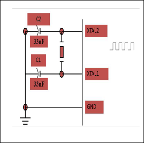
Fig.3 Circuit Diagram
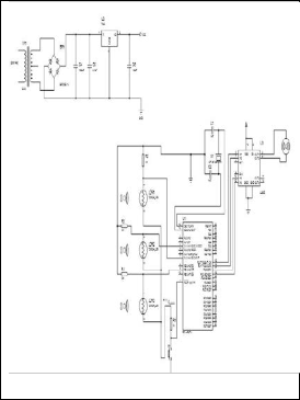
Fig.2 crystal oscillator
2.6 L293D DRIVER
The L293D is a monolithic integrated high voltage, high current four channel driver designed to accept standard DTL or TTL logic levels and drive induc- tive loads (such as relays solenoids, DC and step- ping motors) and switching power transistors. To simplify use as two bridges is pair of channels is equipped with an enable input. A separate supply input is provided form the logic, allowing opera- tional at a low voltage and internal clamp diodes are included. This device is suitable for use in switching applications at frequencies up to 5 KHz.
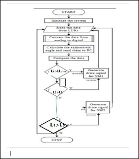
7. SYSTEM SOFTWARE AND OPERATION
The Sun moves nominally 0.25° across an arc of the sky every minute. This means that the speed of rotation is not critical (15,16). To achieve high resolution and low power
consumption a DC motor with high torque gear transmissions was chosen to perform the rotation. Moreover, the sampling from the sensors can be made slow as well, the PIC may take a sample each minute, and this will be fair enough.The flowchart of the control algorithm is as shown in figure.
IJSER © 2014 http://www.ijser.org
International Journal of Scientific & Engineering Research, Volume 5, Issue 12, December-2014 167
ISSN 2229-5518
complex code. It Supports Multiple Configurations within your projects. Supports Multiple Versions of the same compiler . Support for multiple Debug Tools of the same type
3. EXPERIMENTAL RESULTS
Solar panels are as good as power supplies of an average of 12V in bright sunlight. The only problem is unregulated voltage due to variation in intensity of light.
Fig.4 Flow chart
corresponding resistance of the sensor. After read- ing the resistances of sensors A and B, the PIC calcu- latesthe difference between the two readings. if the deference is less than a threshold value, there are two possibilities either the two sensors are under shadow( night time) or both A and B sensors are under the light perpendicularly (facing the day light). In nigtime the PIC command the motor to rotate thetracker to the reset position waiting for the sun from the east
In this case the PIC enters the sleeping mode to save power .In the other hand if sensors A and B both facing the sun, then the PIC commands the motor to stop the motion, using the fast stop mode in the Hbridge
MP LAB STIMULATING SOFWARE
it is a free, integrated toolset for the development of embedded applications on Microchip's PIC and dsPIC microcontrollers.. It is a 32-bit application on Microsoft Windows and includes several free soft- ware components for application development, hardware emulation and debugging . here we are stimulating three ldrs and showing the direction of motor.this method is used to predict the correct output.
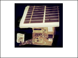
Features: Provides a new Call Graph for navigating
Fig.5 Working model
IC LM 317 solves the problem by regulating the output voltage but it again dissipated 2V across it which makes the system less efficient. One of the major renewable energy source is SUN ENERGY or SOLAR ENERGY. Daily 157PW of power is being radiating on to the earth, but we are not using at least 10% of that energy. If we use at least 50% of that energy, we may not need to use non conven- tional fuels like petrol, coal, etc.
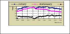
So, we used this technology of sun tracking solar
panel in order to increase the usage of the solar en- ergy. with this procedure a single solar panel can gather more solar energy, when compared to fixed solar panel technique.The measurement results are given in Figure 8. The differences between the tem- perature of rotary panel and that of stationaryone are also given as graphically in Figure 8
.
Fig.6 Output
4.CONCLUSIONS
From the work that has been done it is to be noted
IJSER © 2014 http://www.ijser.org
International Journal of Scientific & Engineering Research, Volume 5, Issue 12, December-2014 168
ISSN 2229-5518
that there has been a significant increase in the total power generated throughout the day and ouput of
12v The paper shows how to develop and imple- ment a single axis solar tracking system with mini- mum cost. The mechanical structure is very simple and reliable, it is designed such that the entire con- troller board fit within the base platform of the sun tracker system.The controller circuit has been de- signed with a minimal number of components, to minimize the cost, and has been integrated onto a single board for simple assembly. The software control for the PIC microcontroller was written in high-level language, the software was simple and easy to understand. The tracking mechanism was successfully achieved with one degree of freedom suing 16F84A PIC micro controller.
ACKNOWLEDGEMENT
This is to declare that this paper has been written by us. No part of the paper is plagiarized from other sources. All information included from other sources have been duly acknowledged.
• Sara sunny is currently pursuing Btech Degree pro- gram in Electrical and Electronics Engineering from Sahrdaya College of Engineering and technolo- gy,kodakara, under University of Calicut. Kerala, In- dia, Area of interests are Renewable energy,Drives & its control.E-mail: sarasunny12@gmail.com
• Anumol jose is currently pursuing Btech Degree pro- gram in Electrical and Electronics Engineering in Sahrdaya College of Engineering and technolo- gy,kodakara, under University of Calicut. Kerala, In- dia. Area of interests are Renewable energy,Power elec- tronics & its control E-mail: anumoljose64@gmail.com
• Jithin.k is currently pursuing Btech Degree program
in Electrical and Electronics Engineering in Sahrdaya College of Engineering and technology,kodakara, un- der University of Calicut.Kerala,India. Area of inter- ests are Renewable energy,Drives & its control, E-mail: jithin.k710@gmail.com
• Joseph jose is currently pursuing Btech Degree pro- gram in Electrical and Electronics Engineering in Sahrdaya College of Engineering and technolo- gy,kodakara, under University of Calicut. Kerala, In- dia, Area of interests are Renewable energy E-mail: meetjosephjose@gmail.com
• Jitha Joseph is currently workingas assistant professor
in Sahradya college of Engineering & Technolo- gy,Kodakara ,under University of Calicut.She pursued B.Tech degree from University of Calicut & M.Tech
from Karunya University ,Coimbatore ,India.Area of research are Power Electronics & Drives,Renewable en- ergy. E-mail: jithajoseph13@gmail.com
5. REFERENCES
1). Lynn, P, A,(2020), “Electricity from Sunlight: An Introduction to Photovoltaics”,1st ed,UK, John Wiley & Sons, Ltd
(2)Plesz,B , Sági,P and Timár Horváth,V,(2009)
“Enhancement of Solar panels’ power generation by the usage of solar tracking Proceedings of ECOpole, Vol. 3, No. 1
(3)barsoum ,N,vasant,p,(2010)”simplified solar tracking prototype”transaction in controller and energy,ES-E11/GJTO online publication,june 2010. (4)Floiyd.T.L(2005),”ElectronicDevices ”7thEd USA,Prentice-Hall
(5). Hewitson, J,(2007), “Design of a micro proces- sor
(6). Sandhu, H, S,(2009), “Running Small Motors Based autoAted sun photometer” with PIC micro- controllers.
IJSER © 2014 http://www.ijser.org