International Journal of Scientific & Engineering Research, Volume 2, Issue 12, December-2011 1
ISSN 2229-5518
Micro Hydro Power: Promising Solution for Off-grid
Renewable Energy Source
Md Tanbhir. Hoq, Nawshad U. A., Md. N. Islam, IbneaSina ,Md. K. Syfullah, Raiyan Rahman
parts of the world.This paper will briefly review the micro hydro current power plant‟s prospect as a possible off grid source of renewable energy.
—————————— ——————————
YDRO power is one of the oldest sources of energy used by human civilization. It has been used hundreds of years
ago to turn waterwheels for different purposes such as grind-
ing grains, sawing logs and manufacturing cloths. Large scale hydroelectric power plants have been being used for generat- ing electricity worldwide from the last century. There are many types of hydropower plant such as dam-reservoir base power plant, ocean tidal power plant, wave power plant and others. In this paper the use and possibility of micro water current turbine is discussed. This type of power production uses the flow of a stream to generate electricity. It does not require dam or reservoir, it only uses the free flowing water from a river or canal or any other streams. They are usually used for meeting small local demand like lighting, charging batteries and other small home appliances. They are cheap and small, and the developing countries may manufacture and im- plement this scheme to help supply the needed electricity to small communities in remote areas such as island formed in river bed. They can produce electricity if the water flow veloc- ity is greater than .5 m/s.
The use of river flow has long been forgotten due to the emer-
gence of large scale power production from fossil fuels main- ly. The burning of fossil fuels has given rise to global warm- ing with the increasing amount of greenhouse gases. All over the world power is mainly generated by burning fossil fuels,
and especially in the developing countries. The generation of power in the developing countries is largely dependent on
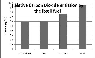
fossil fuels like coal, oil and natural gas. These are the major
contributors of CO2 which is evident from the following chart: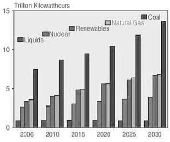
Fig 1: Relative carbon Dioxide emission by the fossil fuel
Fig 2: World Electricity Generation by Fuel [source: EIA
2006 & 2009]
From the figure 2 it is apparent that the amount of energy produced by renewable sources is very less and that will not change if we do not take necessary steps right away. Now we face the environmental challenges these fossil fuel based pow- er production give us, we look for environment friendly tech- nologies for a solution. Small water current turbine could be a solution along with all the other renewable sources for future. The global energy demand is on the rise, its increasing and this can‟t be stopped for the need of people of a better life, so
IJSER © 2011
International Journal of Scientific & Engineering Research, Volume 2, Issue 12, December-2011 2
ISSN 2229-5518
we must find and use renewable sources of energy to meet future demands.
Large scale hydro power plant could have been a better solution, but this technology has got its negative environmen- tal aspects. Large scale hydro power plant needs a dam and reservoir. A dam to create a reservoir may obstruct the migra-
tion of fish and other marine life. A reservoir and a dam also can change the flow characteristic, temperature, marine life diversity, chemistry and silt load amounts. These environmen- tal effects can significantly change the ecology of the river upstream and downstream. These changes may have negative impact on the deltas that form where rivers merge to the ocean. Also reservoirs can cover vast area, agricultural lands, sites and more over it can cause relocation of people living there. Also a quite large amount of greenhouse gasses may also form in reservoirs, depending on the temperature and lo- cation.
On the contrary water current turbines can be used without a dam to generate electricity for home scale remote power systems. These so-called micro-hydro installations can be a very good complement to a solar power system, as they pro- duce electricity 24 hours a day. A micro hydropower plant has a capacity of up to 100 kilowatts. A small or micro hydroelec- tric power system can produce enough electricity for a home, farm, ranch, or village. Small water turbine will produce pow- er non-stop, as long as running water is available, no matter what the other conditions may be.
Micro water current turbines are most suited for places where there is an almost a constant flow of water, throughout the year. The under developed and developing countries can use this techniques to provide electricity to remote places where transmission line cannot be connected easily or the cost becomes very high. And the countries like Bangladesh where there are hundreds of rivers and all of them have got constant flow of water throughout the year, this scheme can be a real solution for power scarcity problems.
Water current turbines, or hydrokinetic turbines, produce elec- tricity directly from the flowing water in a river or a stream. The turbine is placed in the water stream and flowing water enables the turbine to rotate, producing electricity. The energy flux of the water stream is dependent on the density, cross sectional area and velocity cubed. There are many concepts for harnessing this energy, but turbine is being the most com- mon and proven one. The equation governing the turbine out- put power is-
In the energy conversion process we must focus on the type of the turbine, based on the alignment of rotor axis with respect to water flow turbines can be classed in two groups, the axial axis and cross flow turbines. The selection of turbine type depends on the flow type, velocity and desired output of the system which is beyond the scope of this paper. A few types of turbine design scheme are given in the figures below.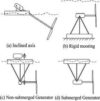
Figure 3: Axial-flow (horizontal) turbines
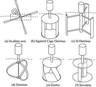
The axial concept has a rotational axis of rotor which is parallel to the incoming water stream. This is illustrated in figure 3. The inclined axis turbines (a) have mostly been stu- died for small river energy converters. The horizontal axis (b, c and d) turbines are common in tidal energy converters and are very similar to modern day wind turbines from design and structural point of view. The cross-flow concept (figure 4) on the other hand, has a rotational axis of rotor which is parallel to the water surface, but orthogonal to the incoming water stream. The advantage of cross-flow turbines is that they can rotate unidirectional even with bi-directional fluid flow.
Where,
P = Power (watt)
P=1/2 ρKAV3
ρ = Water density (kg/m3)
K= Power coefficient
A = Turbine area (m2)
V = Velocity of water (m/s)
IJSER © 2011
International Journal of Scientific & Engineering Research, Volume 2, Issue 12, December-2011 3
ISSN 2229-5518
Figure 4: Cross-flow turbines
Augmentation channels create a pressure within a con- strained area and increase the flow velocity, hence increasing the turbine speed. It can significantly increase the output pow- er. That is why it is also a very important part of the system to consider. There are many augmentation types. Some common types are given in the figure below.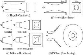
Figure 5: Examples of ducts/diffusers
Complete hydrokinetic system for using in a river or a stream will be comprised of many other components, like mooring, control system, protection screen, generator and oth- ers.
4 THE FLOW OF THE STREAM
Micro water current projects can be run in rivers and streams both, but for this discussion river based plants will be consi- dered only. The very important and most vital part of the project is the river flow and the site selection. The best per- formance can be derived from a linear flow of water, but in rivers the flow characteristic changes stochastically with time, it varies throughout the seasons and even daily. But the river water flow is unidirectional, that provides an edge. So there is no requirement for rotor yawing. The level of power output is directly related to the flow velocity. Usually the volumetric flow data is available, but water velocity can vary with the same flow rate. It can vary with the nature of the channel. The placement of the hydrokinetic system is vital. The velocity is higher on the surface of the water than that of the bottom due to viscosity. The velocity of a river refers to the rate of water movement, often measured on meters per second. The velocity of a river depend on three factors-
River gradient Channel roughness Channel shape
The gradient of the river bed is the ratio between vertical fall over horizontal distance. It is drawn as a graph of distance from source (x-axis) against height above sea level (y-axis). Bed gradient decreases gradually with distance from the source.Channel roughness - pebbles, stones and boulders on the beds and banks increase the roughness of the channel. The wetted perimeter is higher, increasing friction of the river. The shape of the channel or its cross section affects the wetted perimeter. The wetted perimeter refers to the extent to which water is in contact with its channel. The greater the wetted perimeter is, the greater the friction between the water and the banks and the bed of the channel, and the slower the flow of river. So selection of a site is vital. There are models that ex- plain the river characteristics from upstream to downstream. Two models are given here.
The Bradshaw and Schumm Models are geographical models which describe how a river's characteristics vary be- tween the upper course and lower course of a river.
IJSER © 2011
International Journal of Scientific & Engineering Research, Volume 2, Issue 12, December-2011 4
ISSN 2229-5518
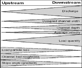
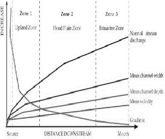
Figure 5: Bradshaw model
Figure 5: Schumm model
Both of them show that discharge, occupied channel width, channel depth and average load quantity increases downstream Load particle size, channel bed roughness and gradient are all characteristics which decrease downstream. These models can be effective in selecting the suitable site for hydrokinetic plants.
River water velocity is relatively lower then water used in large scale dam and reservoir hydro power systems. The water velocity also can fluctuate in a specific area for different time also. As the minimum velocity required for generation of elec- tricity is .5 m/s. and most of the micro hydro power generating unit producing companies calculates speed up to 3 m/s veloci-
ty so in here power generated is calculated from 5 m/s – 3 m/s velocity of the stream.
Power coefficient „k‟ takes a variety of factorsinto ac- count. Each turbine has a different maximum value of „K‟ which indicates the efficiency levels for that turbine.Value of
„k‟ can vary widely from 0.06 - 0.42. The coefficient is quite
low, for calculation value of „k‟ was taken as 0.1, 0.2, 0.3, and
0.4 for four sets of curves.
Another factor for calculation is the turbine area. Turbine varies with the model of turbine chosen; there are many tur- bine models to choose from. And the area will also vary with the different vendors. In this calculation for water current power generation the area is taken a minimum 0.25 m2 up to
3.5 m2..And water density may also vary with many factors, but for simplicity here 1000 kg/m3 is taken. Power output from
these conditions is calculated using the formula. Four different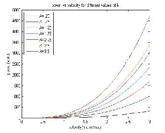
graphs were drawn for four values of co-efficient „k‟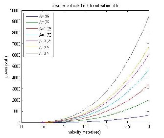
Fig: Power output versus velocity curve for k=.1
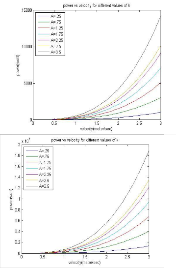
Fig: Power output versus velocity curve for k=.2
IJSER © 2011
International Journal of Scientific & Engineering Research, Volume 2, Issue 12, December-2011 5
ISSN 2229-5518
Fig: Power output versus velocity curve for k=.4
From the calculations done above it is observed that a fairly good
amount of power is being generated when the value of „k‟ is higher, and the velocity of the stream flow is increased. Much more power could have been generated if the value of „k‟ were large. This type of small water current turbine can provide elec- tricity to small group or consumers or some homes. Further stu- dies are to be taken for the implementation of this technology.
.
Fig: Power output versus velocity curve for k=.3
1. Kari Sørnes “Small-scale Water Current Turbines for River Applications”
2.Md. RezaulHasan, Md. Jahidul Islam Razan, Md. ShoaibShahriar, Riasat Siam Islam, S.M.Ferdous “ Nuclear power-aninevitable option for most vulnerable countries from the perspective of environmental degradation”
3. M. J. Khan, M. T. Iqbal, J. E. Quaicoe “A Technology Review and Simulation
BasedPerformance Analysis of River Current Turbine Systems”
4. D. J. Poehls, Gregory John Smith “Encyclopedic dictionary of hydrogeology”
5. Thropton Energy, Physic Lane, Thropton, Northumberland NE65 7HU, United
Kingdom, http://www.throptonenergy.co.uk/
6. Alternative Hydro Solutions Ltd., Suite 421, 323 Richmond Street East, Toron- to, Ontario, M5A 4S7, Canada. http://www.althydrosolutions.com/
7. A.K.M. Sadrul Islam, N.H. Al-Mamun, M.Q. Islam and D.G. Infield, Energy from river current for small scale electricity generation in Bangladesh,
8. Al-Mamun NH. Utilization of river current for small scale electricity generation in Bangladesh.
9. K. Schulze, M. Hunger, and P. D¨oll Simulating river flow velocity on global scale
IJSER © 2011